manuals.online logo
Brands
  1. Home
  2. •
  3. Brands
  4. •
  5. Graco
  6. •
  7. Control Unit
  8. •
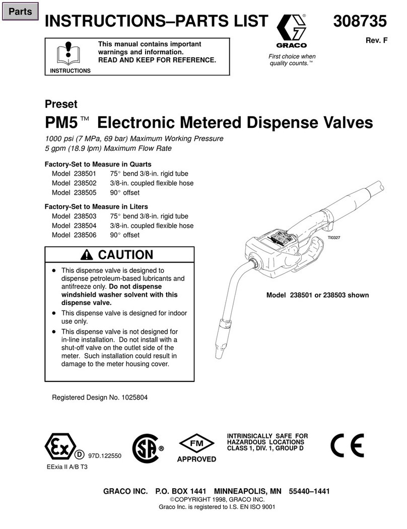
  9. Graco PM5 238513 Operation manual

Graco PM5 238513 Operation manual

This manual suits for next models

5

Other Graco Control Unit manuals

Graco Trabon MD Series User manual

Graco

Graco Trabon MD Series User manual

Graco CGM 25B127 Parts list manual

Graco

Graco CGM 25B127 Parts list manual

Graco 15X303 Technical reference manual

Graco

Graco 15X303 Technical reference manual

Graco Pulse Series Assembly instructions

Graco

Graco Pulse Series Assembly instructions

Graco SDP8 Series Owner's manual

Graco

Graco SDP8 Series Owner's manual

Graco 207861 User manual

Graco

Graco 207861 User manual

Graco 24L096 User manual

Graco

Graco 24L096 User manual

Graco 24P976 User manual

Graco

Graco 24P976 User manual

Graco 24W870 Manual

Graco

Graco 24W870 Manual

Graco 10:1 Dyna-Star 247444 Use and care manual

Graco

Graco 10:1 Dyna-Star 247444 Use and care manual

Graco Series A User manual

Graco

Graco Series A User manual

Graco Gun Flush Box 570046 Operation manual

Graco

Graco Gun Flush Box 570046 Operation manual

Graco 208390 User manual

Graco

Graco 208390 User manual

Graco CSP Series User manual

Graco

Graco CSP Series User manual

Graco Dyna-Star 77X540 User manual

Graco

Graco Dyna-Star 77X540 User manual

Graco SERIES F Operation manual

Graco

Graco SERIES F Operation manual

Graco 222461 Operation manual

Graco

Graco 222461 Operation manual

Graco PD44 Troubleshooting guide

Graco

Graco PD44 Troubleshooting guide

Graco XM PFP Operation manual

Graco

Graco XM PFP Operation manual

Graco Control Architecture Module Owner's manual
Graco

Graco Control Architecture Module Owner's manual

Graco 256994 Operation manual

Graco

Graco 256994 Operation manual

Graco 571169 User manual

Graco

Graco 571169 User manual

Graco 244912 Operation manual

Graco

Graco 244912 Operation manual

Graco 77X542 User manual

Graco

Graco 77X542 User manual

Popular Control Unit manuals by other brands

Seitz 14A80 user manual

Seitz

Seitz 14A80 user manual

Wilo RS485 Installation and operating instructions

Wilo

Wilo RS485 Installation and operating instructions

Becker CentralControl CC41 Commissioning Instruction

Becker

Becker CentralControl CC41 Commissioning Instruction

SICK CDB650 operating instructions

SICK

SICK CDB650 operating instructions

Panduit NetKey NKP5E88M Series installation instructions

Panduit

Panduit NetKey NKP5E88M Series installation instructions

MX Options Concentric Petite Fitting instructions

MX

MX Options Concentric Petite Fitting instructions

Clean Water Systems Fleck 2510 Installation & start?up guide

Clean Water Systems

Clean Water Systems Fleck 2510 Installation & start?up guide

Fairchild FSB44104A user guide

Fairchild

Fairchild FSB44104A user guide

LEGRAND Wattstopper LMIN-104 installation instructions

LEGRAND

LEGRAND Wattstopper LMIN-104 installation instructions

PMK ATT10BNCS instruction manual

PMK

PMK ATT10BNCS instruction manual

Tektronix TDS3FFT user manual

Tektronix

Tektronix TDS3FFT user manual

Woodward easYgen Technical manual

Woodward

Woodward easYgen Technical manual

Balluff BNI EIP-502-105-R015 user guide

Balluff

Balluff BNI EIP-502-105-R015 user guide

NXP Semiconductors TWR-LS1021A Getting started

NXP Semiconductors

NXP Semiconductors TWR-LS1021A Getting started

Advantech PCM-3117 Startup manual

Advantech

Advantech PCM-3117 Startup manual

Danfoss MCO 101 manual

Danfoss

Danfoss MCO 101 manual

Moons' Lin Engineering R701P user manual

Moons'

Moons' Lin Engineering R701P user manual

Aventics RV1 operating instructions

Aventics

Aventics RV1 operating instructions

manuals.online logo
manuals.online logoBrands
  • About & Mission
  • Contact us
  • Privacy Policy
  • Terms and Conditions

Copyright 2025 Manuals.Online. All Rights Reserved.

309377
Rev. A
First choice when
quality counts.t
Model 238511 or 238513 shown
TI0327
INSTRUCTIONS–PARTS LIST
INSTRUCTIONS
This manual contains important
warnings and information.
READ AND KEEP FOR REFERENCE.
Preset
PM5tElectronic Metered Dispense Valves
1000 psi (7 MPa, 69 bar) Maximum Working Pressure
5 gpm (18.9 lpm) Maximum Flow Rate
Factory-Set to Measure in Quarts
Model 238511 75_bend 3/8-in. rigid tube
Model 238512 3/8-in. coupled flexible hose
Model 238515 90_offset
Factory-Set to Measure in Liters
Model 238513 75_bend 3/8-in. rigid tube
Model 238514 3/8-in. coupled flexible hose
Model 238516 90_offset
DThis dispense valve is designed to
dispense petroleum-based lubricants and
antifreeze only. Do not dispense
windshield washer solvent with this
dispense valve.
DThis dispense valve is designed for indoor
use only.
DThis dispense valve is not designed for
in-line installation. Do not install with a
shut-off valve on the outlet side of the
meter. Such installation could result in
damage to the meter housing cover.
CAUTION
Registered Design No. 1025804
GRACO INC. P.O. BOX 1441 MINNEAPOLIS, MN 55440–1441
ECOPYRIGHT 2001, GRACO INC.
Graco Inc. is registered to I.S. EN ISO 9001
Parts
2 309377
Table of Contents
Warnings 2. . . . . . . . . . . . . . . . . . . . . . . . . . . . . . . . . . . . . .
Installation 4. . . . . . . . . . . . . . . . . . . . . . . . . . . . . . . . . . . . .
Setup 7. . . . . . . . . . . . . . . . . . . . . . . . . . . . . . . . . . . . . . . . .
Operation 11. . . . . . . . . . . . . . . . . . . . . . . . . . . . . . . . . . . .
Troubleshooting 13. . . . . . . . . . . . . . . . . . . . . . . . . . . . . . .
Service 16. . . . . . . . . . . . . . . . . . . . . . . . . . . . . . . . . . . . . .
Parts List 18. . . . . . . . . . . . . . . . . . . . . . . . . . . . . . . . . . . . .
Parts Drawing 19. . . . . . . . . . . . . . . . . . . . . . . . . . . . . . . . .
Technical Data 20. . . . . . . . . . . . . . . . . . . . . . . . . . . . . . . .
Dimensional Drawing 21. . . . . . . . . . . . . . . . . . . . . . . . . .
Graco Standard Warranty 22. . . . . . . . . . . . . . . . . . . . . .
Graco Phone Number 22. . . . . . . . . . . . . . . . . . . . . . . . . .
Symbols
Warning Symbol
WARNING
This symbol alerts you to the possibility of serious
injury or death if you do not follow the instructions.
Caution Symbol
CAUTION
This symbol alerts you to the possibility of damage to
or destruction of equipment if you do not follow the
instructions.
EQUIPMENT MISUSE HAZARD
Equipment misuse can cause the equipment to rupture or malfunction and result in serious injury.
DThis equipment is for professional use only.
DRead all instruction manuals, tags, and labels before you operate this equipment.
DUse the equipment only for its intended purpose. If you are not sure, call your Graco distributor
for assistance.
DDo not alter or modify this equipment. Use only genuine Graco parts and accessories.
DDo not leave this dispense valve unattended while it is dispensing.
DCheck equipment daily. Repair or replace worn or damaged parts immediately.
DDo not exceed the maximum working pressure of the lowest rated system component. See the
Technical Data on page 20 for the maximum working pressure of this component.
DUse fluids and solvents that are compatible with the equipment wetted parts. See the Technical
Data section of all equipment manuals. Read the fluid and solvent manufacturer’s warnings.
DRoute hoses away from traffic areas, sharp edges, moving parts, and hot surfaces. Do not
expose Graco hoses to temperatures above 180_F (82_C) or below –40_F (–40_C).
DComply with all applicable local, state, and national fire, electrical, and safety regulations.
DDo not point the dispense valve at anyone or at any part of the body.
DDo not put your hand or fingers over the end of the dispense valve.
DDo not stop or deflect leaks with your hand, body, glove, or rag.
DUse only extensions and nozzles that are designed for use with this dispense valve.
DFollow the Pressure Relief Procedure on page 5 before you clean, check, or service this
equipment.
DTighten all fluid connections before you operate this equipment.
DCheck the hoses, tubes, and couplings daily. Replace worn or damaged parts immediately. Do
not repair high pressure couplings; you must replace the entire hose.
WARNING
WARNING
INSTRUCTIONS
3309377
FIRE AND EXPLOSION HAZARD
Improper grounding, poor ventilation, open flames, or sparks can cause a hazardous condition and
result in a fire or explosion and serious injury.
DBe sure the entire fluid system is properly grounded. Refer to your pump instruction manual for
complete details. See Grounding on page 6.
DIf there is any static sparking or you feel an electric shock while using this equipment, stop dis-
pensing immediately. Do not use the equipment until you identify and correct the problem.
DProvide fresh air ventilation to avoid the buildup of flammable fumes from solvents or the fluid
being dispensed.
DKeep the dispensing area free of debris, including solvent, rags, and spilled gasoline.
DDo not smoke while flammable fluids or fumes are in the dispensing area.
WARNING
WARNING
4 309377
Installation
Typical Installations
Fig. 1 shows a typical hose reel installation. These
dispense valves can also be installed on a console, as
shown in Fig. 2.
Do not use this dispense valve on non-Graco
consoles. Such use could result in the trigger
becoming inadvertently pressed while the
dispense valve is stowed.
CAUTION
Fig. 1
L
M
K
N
J
H
06174B
KEY DESCRIPTION
HThermal relief kit (required) Part No. 235998
Install downstream from pump.
JFluid shut-off valve
K Hose
LHose reel fluid inlet hose
MHose reel
NPM5 electronic metered dispense valve
The typical installation shown in Fig. 1 is only a guide.
The components shown are typical; however, it is not a
complete system design. Contact your Graco
distributor for assistance in designing a system to suit
your particular needs.
This dispense valve is not designed for in-line
installation. Do not install with a shut-off valve
on the outlet side of the meter. Such installation
could result in damage to the meter housing
cover.
CAUTION
Mounting Bracket
Mounting bracket 196471 is available for resting a PM5
dispense valve on a console. See Fig. 2.
Do not obstruct the trigger of this dispense
valve, and do not set the unit down resting on its
trigger, or it might not stop dispensing.
CAUTION
mounting bracket
196471
Fig. 2 TI0334
5309377
Installation
PRESSURIZED EQUIPMENT HAZARD
The equipment stays pressurized until pressure is
manually relieved. To reduce the risk of serious
injury from pressurized fluid, accidental spray from
the dispense valve, or splashing fluid, follow the
Pressure Relief Procedure when you
DAre instructed to relieve pressure
DCheck, clean, or service any system equipment
DInstall or clean fluid nozzles or filter
WARNING
Pressure Relief Procedure
1. Turn off the power supply to the pump.
2. Trigger the dispense valve into a waste container
to relieve pressure.
3. Open any bleed-type master air valves and fluid
drain valves in the system.
4. Leave the drain valve open until you are ready to
pressurize the system.
FIRE AND EXPLOSION HAZARD
The movement of fluids through the
dispensing system generates static
electricity. The static electricity can
cause volatile fumes to ignite, resulting in explosion
and fire. The dispensing system must grounded.
See Grounding on page 6.
WARNING
Pre-Installation Procedure
1. Relieve the pressure.
WARNING
To reduce the risk of serious injury whenever you
are instructed to relieve pressure, always follow the
Pressure Relief Procedure above.
2. Close the shut-off valve (item J in Fig. 1).
3. Ground the hose and reel or console. See
Grounding on page 6. Leave a minimum two
engaged threads bare when using Rtape.
The bare threads ensure a ground is maintained.
Installation Procedure
If this is a new installation, or if the fluid in the
lines is contaminated, flush the lines before you
install the metered valve. Contaminated lines
could cause the valve to leak.
CAUTION
1. If this is an existing installation, go to step 7.
Steps 2 through 6 are the Flushing Procedure.
2. Close the fluid shut-off valve (J) at each dispense
position.
3. Make sure the main fluid outlet valve at the pump
is closed, the air pressure to the pump motor is
adjusted, and the air valve is open. Slowly open
the main fluid valve.
4. Place the hose end (with no dispense valve
connected) into a container for waste oil. Secure
the hose in the container so it will not come out
during flushing. If you have multiple dispense
positions, first flush the dispense position farthest
from the pump, and work your way toward the
pump.
5. Slowly open the shut-off valve (J) at the dispense
position. Flush out a sufficient amount of oil to
ensure that the entire system is clean, and close
the valve.
6. Repeat step 5 at all other dispense positions.
7. Relieve the pressure.
WARNING
To reduce the risk of serious injury, whenever you
are instructed to relieve pressure, always follow the
Pressure Relief Procedure at left.
8. Slide the swivel cover (4) of the PM5 onto the
hose, small end first. See Fig. 3.
9. Apply thread sealant to the male threads of the
hose fitting, thread the hose fitting into the swivel
(3) of the PM5, and tighten it firmly. See Fig. 3.
NOTE: Make sure you let the sealant cure to the
manufacturer’s recommendations before you let
fluid into the system.
PTFE
6 309377
Installation
10. Thread the sealing nut (5c, 6c, or 7c) onto the
extension (5a) or street elbow (6d or 7d), thread
the extension or elbow in at least three full turns,
position it for proper alignment, and tighten the
sealing nut. The Rseal on the sealing nut
must face the valve housing. See Fig. 4.
NOTE: The flexible extension (6a) can also be
threaded directly into the meter outlet without the
street elbow or sealing nut. See the note in the
Parts Drawing on page 19.
11. Thread the new nozzle (5b, 6b, or 7b) onto the
extension, and, with an open-end adjustable
wrench, tighten it firmly. See Fig. 4.
NOTE: Only tighten the nozzle with the wrench
on the flats of the nozzle bushing. Do not
disassemble the bushing from the nozzle.
Disassembly will affect the performance of the
nozzle.
WARNING
Do not use Graco’s old nozzle (Part No. 203655) or
any other manual shut-off nozzle on the PM5
extension. You must use the new automatic nozzle
that is provided with the PM5, or the meter could
be damaged. Do not use any sealant material.
12. Open all dispense position shut-off valves, and
start the pump to pressurize the system. See the
Operation section for proper operation of meter.
13. To ensure dispensing accuracy, purge all air from
the fluid lines and dispense valve before you use
it. Set the system flow to the desired flow rate,
which is typically 1.5 gpm. Do not exceed a 5-gpm
flow rate.
3
hose fitting
Slide onto
hose before
connecting.
Fig. 3
4
TI0328
hose
5c
4
5a
5b
Model shown has
75_bend rigid
extension
Fig. 4
Nozzle is not serviceable.
nozzle bushing
TI0327
Grounding
Proper grounding is an essential part of maintaining a
safe system.
To reduce the risk of static sparking, ground all system
components according to local and national electrical
codes. Refer to the user manuals for the pump and
other system components, and ground the following:
DPump: Follow the manufacturer’s recommend-
ations.
DAir and Fluid hoses: Use only grounded hoses.
DAir compressor: Follow the manufacturer’s
recommendations.
DFluid supply container: Follow the local code.
To maintain grounding continuity when flushing or
relieving pressure, always hold a metal part of the
valve firmly to the side of a grounded metal pail, then
trigger the valve.
PTFE
7309377
Setup
Terms
The following terms are shown on the display and/or
used often in this instruction manual.
DR–TOTAL: resettable total
Displayed to show the cumulative amount that the
dispense valve has dispensed in all modes. It can
be reset to zero.
DTOTAL: non-resettable total
Displayed to show the cumulative amount that the
dispense valve has dispensed in all modes for the
history of the unit. It cannot be reset.
DMANUAL mode
Dispense mode in which the display counts up from
zero to show the dispensed amount. In this mode,
you may lock the trigger, but you must manually
unlock it when the desired amount is dispensed.
Memory setting also unlocks the trigger.
DAUTO mode
Dispense mode in which a preset, user-entered
amount is dispensed. When the preset amount is
dispensed, a beep sounds, the trigger unlocks to
stop the unit from dispensing, and the amount
dispensed is displayed. At this point, you may
dispense more by pulling back the trigger, and the
display resumes counting up in Manual mode.
DAsleep / Awake
Asleep is a battery-saving mode in which the
display goes blank after 45 seconds of inactivity
during normal operation and 2 minutes when in the
options menu. The display comes awake from
sleep mode when you press the Manual/Reset or
Auto/Reset button, but not when you squeeze the
trigger to dispense fluid. The unit does keep track
of the amount dispensed while the display is
asleep.
NOTE: If the unit falls asleep after any dispense
cycle, and you do wake it up by pressing the
Auto/Reset button, the previously dispensed
amount is cleared, and the Auto mode dispense
amount stored in memory is displayed. You will be
at the beginning of an Auto mode dispense cycle.
If the unit falls asleep after any dispense cycle, and
you do not wake it up by pressing the
Manual/Reset or Auto/Reset button, it will default to
manual mode. When dispensing begins you will be
at the beginning of a manual mode dispense cycle.
Keypad Buttons
The buttons on the keypad and their functions are as
follows (see the figure below):
D10, 1.0, and 0.1
Used in Auto mode and during setup to enter
dispense amounts.
DMANUAL / RESET and AUTO / RESET
Used individually to select Manual mode and Auto
mode. Used together (pressed simultaneously) to
access the setup menus.
For both of these buttons, the first push selects the
mode, and the second push resets the display to
zero.
DTOTAL
Used in any mode to see the resettable total and
the non-resettable total.
NOTE: All buttons are disabled while fluid is being
dispensed.
06044A
AUTO
GAL
8 309377
Setup
Selecting Dispensing Options
This is the procedure for setting or changing the resettable total, units of measurement, calibration factor, auto
preset amount, and shut-off default amount:
1. If the display is asleep, wake it up by pressing the Manual/Reset or Auto/Reset button.
2. To enter the dispensing options menus from any mode, press and hold the Manual/Reset and Auto/Reset
buttons simultaneously for four seconds.
The first menu is the Resettable Total menu, which is described in the first subsection below. You can advance
through the menus by pressing the Auto/Reset button. You will know which menu you are in, because a menu
indicator will be blinking in the display. The value that is displayed when you leave each menu and advance to
the next is the value that gets stored.
Resettable Total
In this menu, you can reset the resettable total to zero
or leave it unchanged. The resettable total
accumulates until the next time it is manually reset.
1. If you have not already entered the dispensing
options menus, do steps 1 and 2 in Selecting
Dispensing Options above.
2. With R–TOTAL blinking and the current resettable
total displayed, as shown below, do ONE of the
following two options:
DPress the Manual/Reset button.
The resettable total is set to zero, and 0 GAL
or 0 LITERS is displayed.
You can press the Manual/Reset button again
to toggle between zero and the previously
displayed resettable total. To lock in the
displayed value and advance to the Units of
Measurement menu, press the Auto/Reset
button.
OR
DPress the Auto/Reset button.
The currently displayed value is stored, and
the display advances to the Units of
Measurement menu.
R-TOTAL
GAL
06044A
! CAUTION
To prevent overfills and spills
Maximum Working Pressure 7 MPa (70 bar, 1000 PSI)
DDo not obstruct the trigger
DDo not leave unattended
DDo not operate below 32_F (0_C)
DRead instruction manual
Units of Measurement
In this menu, you can set the units of measurement to
quarts, gallons, pints, or liters.
1. If you have not already entered the dispensing
options menus, do steps 1 and 2 in Selecting
Dispensing Options above.
2. Press the Auto/Reset button repeatedly until QTS,
GAL, LITERS, or PTS blinks to indicate that you
are in the Units-of Measurement menu.
3. With QTS, GAL, LITERS, or PTS blinking, as
shown below, do ONE of the following two options:
DPress the Manual/Reset button.
Each time you press the Manual/Reset button,
the display scrolls to the next unit of
measurement. To lock in the new unit of
measurement and advance to the Calibration
Factor menu, press the Auto/Reset button.
OR
DPress the Auto/Reset button.
The displayed unit of measurement is retained,
and the display advances to the Calibration
Factor menu.
GAL
06044A
! CAUTION
To prevent overfills and spills
Maximum Working Pressure 7 MPa (70 bar, 1000 PSI)
DDo not obstruct the trigger
DDo not leave unattended
DDo not operate below 32_F (0_C)
DRead instruction manual
9309377
Setup
Calibration Factor
In this menu, you can recalibrate the meter for different
fluids.
1. If you have not already entered the dispensing
options menus, do steps 1 and 2 in Selecting
Dispensing Options on page 8.
2. Press the Auto/Reset button repeatedly until CAL
blinks and the current calibration factor is
displayed to indicate that you are in the Calibration
menu.
3. With CAL blinking, you can press the Auto/Reset
button and choose not to change the calibration
factor, which advances to the Auto Preset Amount
menu.
OR
You can recalibrate the meter as follows:
3a. If the unit of measurement is liters, dispense
exactly one liter of fluid into a calibrated
1-liter container. If the unit of measurement
is gallons, pints, or quarts, dispense exactly
one quart of fluid into a calibrated 1-quart
container. For proper calibration, you must
dispense the exact amount, according to the
markings on the container.
After dispensing, the displayed number is the
new calibration factor. The new calibration
factor must be within 20 percent of the
factory default value [in the range of 294 gal.
(310 liters) to 442 gal. (467 liters)], or it will
not be accepted.
The following table lists approximate
calibration factors for different fluids. Your
calibration number may vary slightly due to
temperature or flow rate.
Calibration Number
Fluid Quarts Liters
oil (10W–30) 368 389
gear lube 368 389
automatic
transmission
fluid
368 389
antifreeze 347 367
Calibration factors at 70_F (21_C) at 2.0 gpm (7.6 lpm).
3b. Press the Auto/Reset button to store the new
calibration factor and advance to the Auto
Preset Amount menu.
Auto Preset Amount
In this menu, you can specify an amount to be
displayed when you enter the Auto dispense mode.
Typically, you would enter the amount you most
frequently dispense.
1. If you have not already entered the dispensing
options menus, do steps 1 and 2 in Selecting
Dispensing Options on page 8.
2. Press the Auto/Reset button repeatedly until
AUTO blinks and the auto preset amount in
memory is displayed to indicate that you are in the
Auto Preset Amount menu. This is the amount
that is displayed when the Auto/Reset button is
pressed during normal operation.
3. With AUTO blinking and the stored auto preset
amount displayed, as shown below, do ONE of the
following two options:
DEnter a new auto preset amount by pressing
the 10 button to change the 10s digit,
the 1.0 button to change the 1s digit, and
the 0.1 button the change the first decimal
digit.
In the figure below, the arrows point from the
numbered buttons on the keypad to the
corresponding digits in the display.
NOTE: If you press and hold the 10, 1.0, or
0.1 buttons, the digits advance rapidly.
To store the displayed auto preset amount in
memory and advance to the Shut-Off Default
Amount menu, press the Auto/Reset button.
OR
DPress the Auto/Reset button.
The currently displayed auto preset amount is
retained, and the display advances to the
Shut-Off Default Amount menu.
! CAUTION
To prevent overfills and spills
Maximum Working Pressure 7 MPa (70 bar, 1000 PSI)
DDo not obstruct the trigger
DDo not leave unattended
DDo not operate below 32_F (0_C)
DRead instruction manual
06044A
AUTO
GAL
10 309377
Setup
Shut-Off Default Amount
The shut-off default amount is for preventing
accidental overfills when dispensing with the trigger
locked in Manual mode. The shut-off default amount is
factory preset at 5 quarts.
In this menu, you can change the shut-off default
amount.
1. If you have not already entered the dispensing
options menus, do steps 1 and 2 in Selecting
Dispensing Options on page 8.
2. Press the Auto/Reset button repeatedly until the
clock icon blinks, and the stored shut-off default
amount is displayed to indicate that you are in the
Shut-off Default Amount menu.
3. With the clock icon blinking and the stored shut-off
default amount displayed, as shown below, do
ONE of the following two options:
DEnter a new shut-off default amount by
pressing the 10 button to change the 10s digit,
the 1.0 button to change the 1s digit, and
the 0.1 button the change the first decimal
digit. You cannot enter zero. To lock in the
new shut-off default amount and exit the
dispensing options menus, press the
Auto/Reset button.
The PM5 beeps and returns to the Manual
dispense mode to indicate that you have
exited the dispensing options menus.
OR
DPress the Auto/Reset button.
The PM5 beeps and returns to the Manual
dispense mode to indicate that you have
exited the dispensing options menus.
QTS
06044A
! CAUTION
To prevent overfills and spills
Maximum Working Pressure 7 MPa (70 bar, 1000 PSI)
DDo not obstruct the trigger
DDo not leave unattended
DDo not operate below 32_F (0_C)
DRead instruction manual