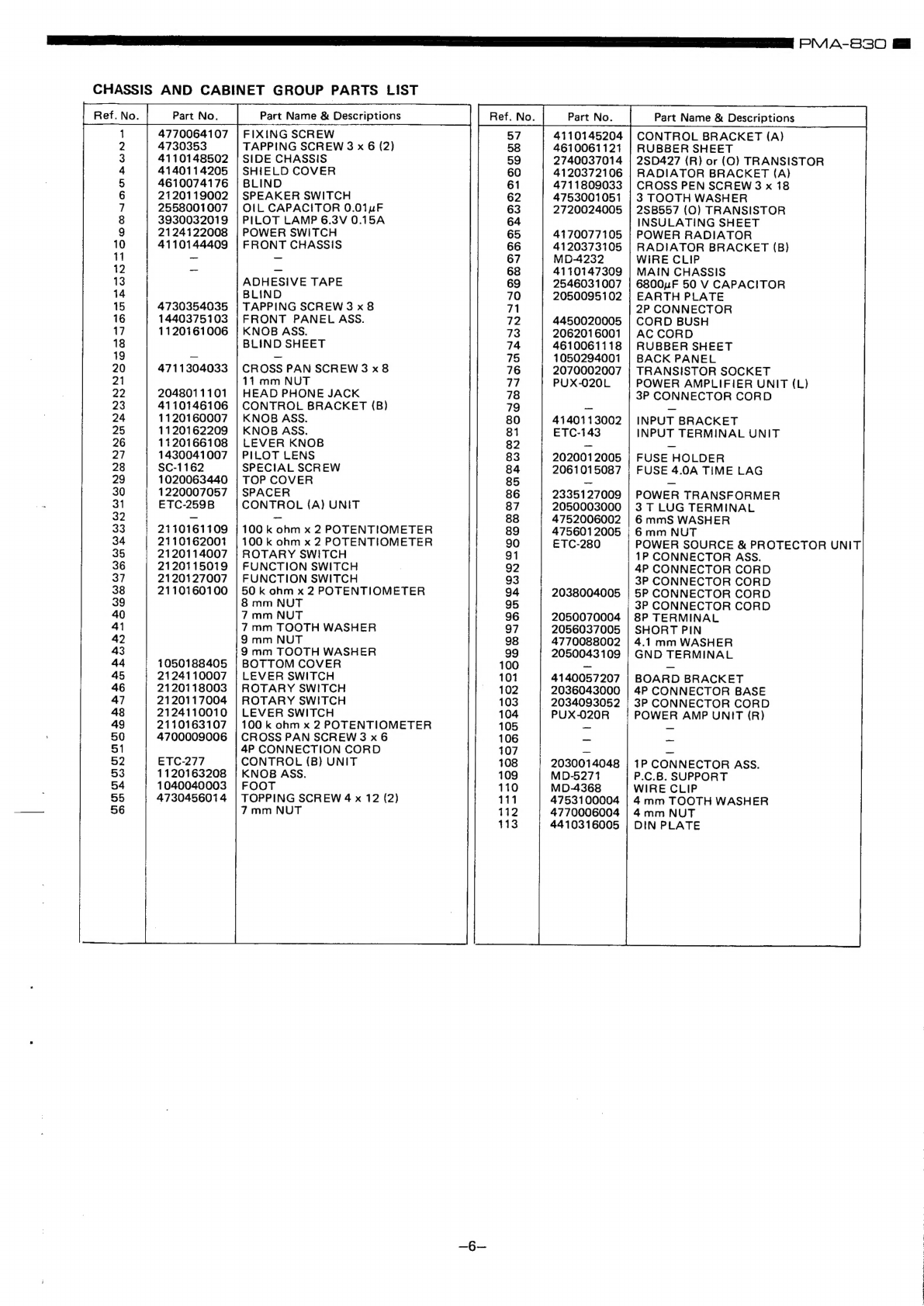
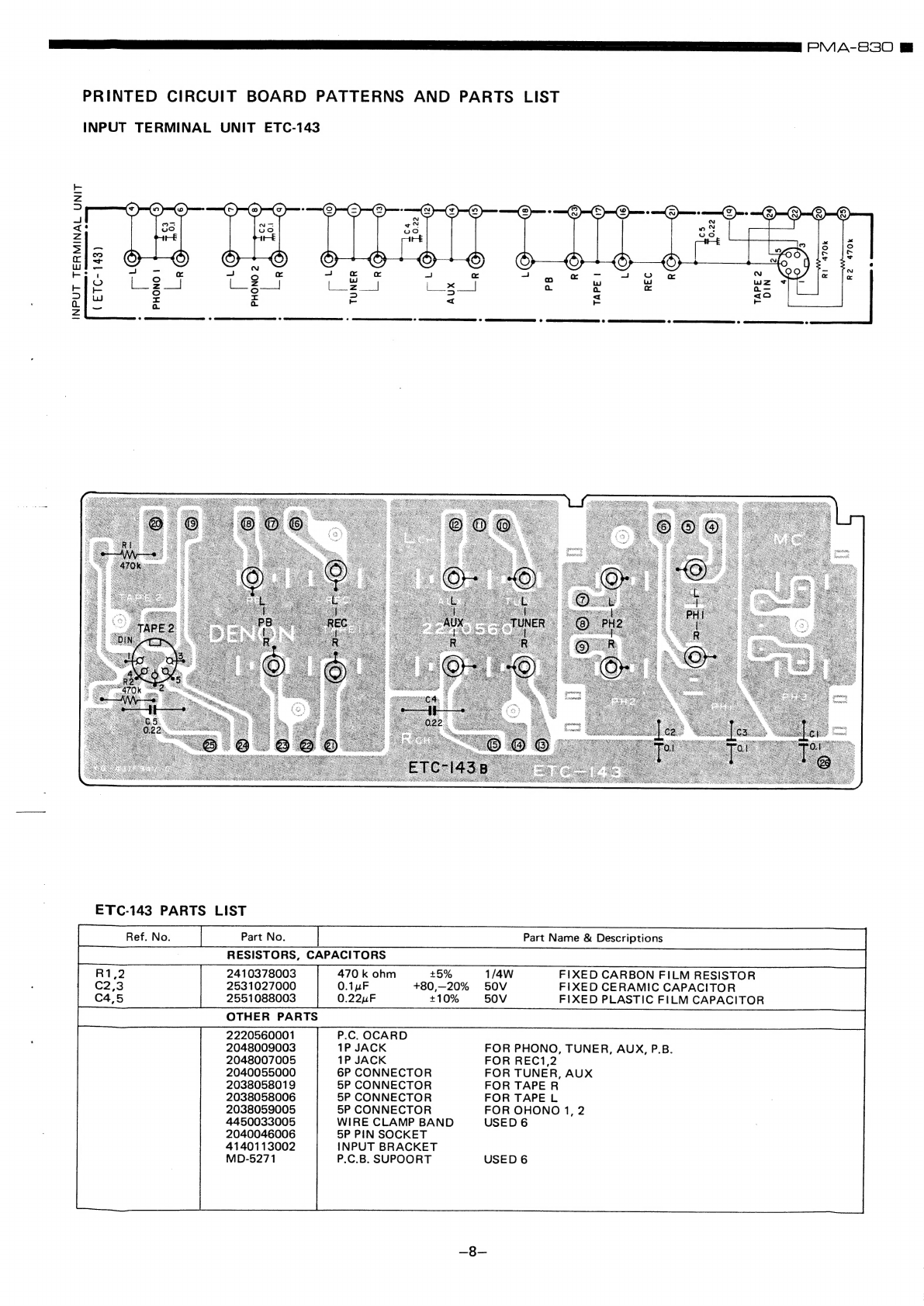
Denon PMA-830 User manual
Other Denon Amplifier manuals

Denon
Denon PMA-850 User manual

Denon
Denon POA-A1HDCI User manual

Denon
Denon PMA-2000R User manual

Denon
Denon PMA-900HNE User manual

Denon
Denon PMA-300V User manual

Denon
Denon PMA-2500N User manual

Denon
Denon PMA-1500AE User manual

Denon
Denon PRA-S10 User manual

Denon
Denon PMA-1055R User manual

Denon
Denon DA-10 User manual

Denon
Denon AVP-A1HDE User manual

Denon
Denon AV SURROUND RECEIVER AVR-5308CI Administrator guide

Denon
Denon PMA-201SA User manual

Denon
Denon POA-3012CI - Multi-Zone Audio Distribution Power... User manual

Denon
Denon PMA-A100 User manual

Denon
Denon PMA-50 User manual

Denon
Denon POA-2200 User manual

Denon
Denon AVP-A1HD User manual

Denon
Denon PMA-510AE User manual

Denon
Denon AVC-A11XV User manual