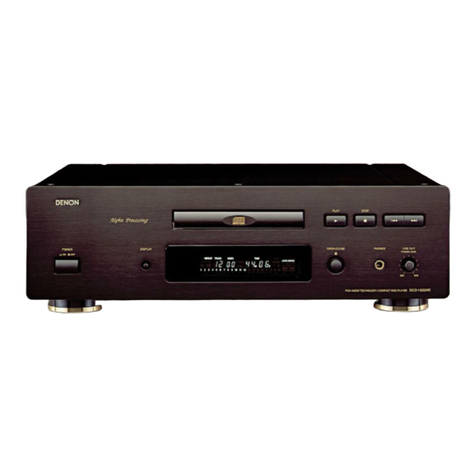
Denon DCD-1500AE User manual

SERVICE MANUAL
SUPER AUDIO CD PLAYER
MODEL DCD-1500AE
TOKYO, JAPAN
Denon Brand Company, D&M Holdings Inc.
Some illustrations using in this service manual are
slightly different from the actual set.
●
Please use this service manual with referring to the
operating instructions without fail.
●
For purposes of improvement, specifications and
design are subject to change without notice.
●
●
本文中に使用しているイラストは、説明の都合上現物
と多少異なる場合があります。
●
修理の際は、必ず取扱説明書を参照の上、作業を行っ
てください。
サービスをおこなう前に、このサービスマニュアルを
必ずお読みください。本機は、火災、感電、けがなど
に対する安全性を確保するために、さまざまな配慮を
おこなっており、また法的には「電気用品安全法」に
もとづき、所定の許可を得て製造されております。
従ってサービスをおこなう際は、これらの安全性が維
持されるよう、このサービスマニュアルに記載されて
いる注意事項を必ずお守りください。
●
本機の仕様は性能改良のため、予告なく変更すること
があります。
●
補修用性能部品の保有期間は、製造打切後8年です。
注 意
X0243 V.01 DE/CDM 0508
For Europe model
Ver. 1

2
DCD-1500AE
SAFETY PRECAUTIONS
The following check should be performed for the continued protection of the customer and service technician.
LEAKAGE CURRENT CHECK
Before returning the unit to the customer, make sure you make either (1) a leakage current check or (2) a line to chassis
resistance check. If the leakage current exceeds 0.5 milliamps, or if the resistance from chassis to either side of the
power cord is less than 460 kohms, the unit is defective.
LASER RADIATION
Do not stare into beam or view directly with optical instruments, class 3A laser product.
注 意
注意事項をお守りください!
サービスのとき特に注意を必要とする個所について
は、キャビネット、部品、シャーシなどにラベルや
捺印で、注意事項を表示しています。これらの注意
書きおよび取扱説明書などの注意事項を必ずお守り
ください。
感電に注意!
(1)このセットは、交流電圧が印加されていますの
で、通電時に内部金属部に触れると感電するこ
とがあります。従って通電サービス時には、絶
縁トランスの使用や手袋の着用、部品交換に
は、電源プラグを抜くなどして、感電にご注意
ください。
(2)内部には、高電圧の部分がありますので、通電
時の取扱には、十分ご注意ください。
指定部品の使用!
セットの部品は難燃性や耐電圧など安全上の特性を
持ったものとなっています。従って交換部品は、使
用されていたものと同じ特性の部品を使用してくだ
さい。特に配線図、部品表に 印で指定されている
安全上重要な部品は必ず指定のものをご使用くださ
い。
部品の取付けや配線の引きまわしは、元どおりに!
安全上、テープやチューブなどの絶縁材料を使用し
たり、プリント基板から浮かして取付けた部品があ
ります。また内部配線は引きまわしやクランパーに
よって発熱部品や高圧部品に接近しないように配慮
されていますので、これらは必ず元どおりにしてく
ださい。
サービス後は安全点検を!
サービスのために取り外したねじ、部品、配線など
が元どおりになっているか、またサービスした個所
の周辺を劣化させてしまったところがないかなどを
点検し、外部金属端子部と、電源プラグの刃の間の
絶縁チェックをおこなうなど、安全性が確保されて
いることを確認してください。
サービス、点検時には次のことにご注意願います。
注 意
安全上重要な部品について
(絶縁チェックの方法)
電源コンセントから電源プラグを抜き、アンテナ
や、プラグなどを外し、電源スイッチを入れま
す。500V絶縁抵抗計を用いて、電源プラグのそれ
ぞれの端子と、外部露出金属部〔アンテナ端子、
ヘッドホン端子、マイク端子、入力端子など〕と
の間で、絶縁抵抗値が1MΩ以上であること、この
値以下のときは、セットの点検修理が必要です。
本機に使用している多くの電気部品、および機構部品
は安全上、特別な特性を持っています。この特性はほ
とんどの場合、外観では判別つきにくく、また、もと
の部品より高い定格(定格電力、耐圧)を持ったもの
を使用しても安全性が維持されるとは、限りません。
安全上の特性を持った部品は、このサービスマニュア
ルの配線図、部品表につぎのように表示していますの
で、必ず指定されている部品番号のものを使用願いま
す。
(1) 配線図…
(2) 部品表… マークで表示しています。
マークで表示しています。
指定された部品と異なるものを使用し
た場合には、感電、火災などの危険を
生じる恐れがあります。
注 意
安全上重要な部品について

3
DCD-1500AE
各部のはずしかた
(組み立てるときは、逆の順序でおこなってください。)
1. トップカバーのはずしかた
(1) トップカバーを取り付けている上部、両サイドの
ネジ 8 本およ後部のネジ 2 本をはずします。
2. フロントパネルのはずしかた
(1) ローダーを開き、ローダーパネルを矢印の方向に
はずします。
(2) フロントパネル底部のネジ 4 本をはずします。
(3) フロントパネル上部のネジ 2 本をはずします。
(4) H/PBRACKET と CHASSIS を共締めしているネジ
をはずします。(Fig.1 参照)
(5) フロントパネルを矢印の方向にはずします。
DISASSEMBLY
(Follow the procedure below in reverse order when
reassembling.)
1. Top Cover
(1) Remove 8 top and side screws. And remove 2 rear
screws, then detach the Top cover.
2. Front Panel Ass’y
(1) Detach the Loader panel Ass’y by lifting.
(2) Remove 4 top screws and 2 bottom screws of Front
Panel Ass’y.
(3) Remove H/P BRACKET and CHASSIS screw, then
detach the Front Panel Ass'y.
(Refer to Fig. 1)
Fig. 1

4
DCD-1500AE
3. メカのはずしかた
(1) メカを取り付けているネジ 4 本をはずします。
4. メカの取り付けかた
(1) MECHABRACKETBOTTOM にメカを置く。
(2) ADJUST.COLLAR を前側 2ヶ所にセットする。
(3) 前側 2ヶ所をネジ止めする。
(4) 後側 2ヶ所をネジ止めする。
5. H/Pブラケットの取り付けかた
図のような順番にて取り付けてください。
(1) ボリューム横をネジ止めする。
(2) H/P ジャック横をネジ止めする。
(3) (4) H/P ジャック上側をネジ止めする。
3. Mechanism
(1) Remove 4 screws, then detach the Mechanism.
4. Attachment of Mechanism
(1) Mechanism is put on MECHA BRACKET BOTTOM.
(2) ADJUST.COLLAR is put on 2 places of the front.
(3) 2 front side screws are tightened.
(4) 2 rear side screws are tightened.
5. Attachment of Mechanism
Follow the procedure below.
(1) 1 screw of volume side is tightened.
(2) 1 screw of H/P jack side is tightened.
(3) (4) 2 screws of H/P jack top is tightened.
ADJUST. COLLAR
MECHA BRACKET BOTTOM
1342
(Note) When assembling the volume pwb and the bracket,
insert thickness 1.6mm board between the bracket
and volume.
( 注 ) ボリュームを H/P ブラケットに取り付けるとき
ボリュームの上部と H/P ブラケットの曲げの間に
1.6mm 厚のスペーサを挟み込む。

5
DCD-1500AE
Note Handling and Replacement of the
Laser pick-up
1. Disassembly
Do not disassemble or adjust this mechanism due to preci-
sion component.
2. Storage
Do not leave this mechanism in high temperature and hu-
midity. Be sure to prevent this mechanism from static elec-
tricity, dust and excessive forces.
Do not leave this mechanism without a unti-static cover for
the dust.
3. Handling
Do not shock to this mechanism.
Don't touch the parts as follows.To touch them may cause
big trouble.
①Trim-potentionmeter
②CD laser dode and Fixate of CD laser
③Fixate plate of OEIC
④High frequency module and DVD laser diode
⑤Objective
⑥Actuator (Include screw, spring, and connected point
actuator and PWB)
※The laser diode soldering portion of ②and ④is sharp,
be careful especially because it is dangerous.
⑥アクチュエータ
Actuator
② CDLD 固定用プレート
FixateplateofCDlaser
⑤対物レンズ
Objective
ネジ
Screw
おさえばね
Spring
Fig.b Fig.c
③ OEIC 固定用プレート
FixateplateofOEIC
④高周波重畳モジュール部 (DVD レーザ用 )
HighfrequencymoduleandDVDlaser
アクチュエ−タと FPC の接合部
ConnectedpointactuatorandPWB
①半固定抵抗 ( 2箇所 )
Trim-potentiometer
レーザーピックアップ取り扱い上の注意
と交換
1. 分解
本メカニズムは、専門工場で、精密に組立て調整しており
ます。安易に分解、調整を行わないで下さい。
2. 保管
高温、あるいは高湿度下での保管は避けて下さい。静電
気、塵埃対策を行い異常な外力が加わらないように保管し
て下さい。
放置する場合は、必ず静電袋に入れて塵埃を避けて下さ
い。
3. 取り扱い
落下などの、強い衝撃がかからないように取扱って下さ
い。
次に示す個所には絶対に触れないで下さい。触れた場合
ピックアップの品質に大きく影響を及ぼす可能性があり
ます。
① 半固定抵抗
② CDLD 固定用プレート(CD レーザ及び本体について
いるプレート)
③ OEIC 固定用プレート
④ 高周波重畳モジュール部 (DVDLD)
⑤ 対物レンズ
⑥ アクチュエータ(ネジ、おさえばね、アクチュエータ
と FPC の接合部含む)
※ ②及び④の LD はんだ付け部はリードカット処理を施し
ており、鋭利になっている為、危険ですので特に注意し
てください。

6
DCD-1500AE
Never touch the objective lens, actuator, laser diode, photo
detector and the trim-potentiometer.
Be sure no dust or soil on the objective lens.
If dust is on the objective lens, below it away by clean air.
If dust or soil remain on the objective lens, use the cleaning
liquid (B4) made by JCB INDUSTRY Ltd. No alternative.
Make sure that a person who handles this mechanism is
well earthed. Be sure to earth to the manufacturing equip-
ment.
Do not approach magnetic materials.
Too much forces on the leads of laser diode, OEIC, and the
printed wiring board, may caused the pickup to damage.
Too much forces on the leads of laser diode, OEIC, and the
printed wiring board, may caused the pickup to damage.
Guide shafts in mechanism should not be forced when you
set the FFC to the connector, which may cause the guide
shafts to deform.
4. Surrounding atmosphere
For proper operation storage and operating environment
should not contain corrosive gases. For example HS2, SO2,
NO2, Cl2ets. In addition storage environment should not
have materials that emit corrosive gases especially from si-
licic, cyanic, formalin and phenol group. In the mechanism
or set, existence of corrosive gases may cause no rotation
in motor.
5. Laser drive circuit
We solder the Short land on PWB before shipment to pro-
tect laser diode. Open the short landsafte you connect
pick-up your circuit by flat cable. (Refer to Fig. a)
When you unstrap the short solder for the laser diode pro-
tection in the condition which doesn't connect by a flat ca-
ble, the laser diode and PEIC may destroy by static
electricity.
レーザダイオード保護用ランド
Theshortlandforthelaserdiode
protection
Fig.a
セットへ接続されていること
Beconnectedtothecircuit
フラットケーブル
Flatcable
ピックアップコネクタ
Connectorofthepickup
対物レンズ、アクチュエータ、レーザーダイオード、光検
出器、及び半固定抵抗には絶対に触れないで下さい。
対物レンズに、塵埃や汚れが付かないように充分注意して
下さい。
対物レンズに埃が付いた場合、きれいな空気を吹き付けて
取り去って下さい。
取りきれない埃、汚れがある場合にはクリーニング液(日
本綿棒(株)CD レンズクリーナー液 B4)を用い、糸屑
の発生しない綿棒で軽く拭き取って下さい。尚、他のク
リーニグ液は絶対に使わないで下さい。
取り扱う作業者は、人体アースを確実に取って下さい。作
業場、治工具など、関連設備は確実にアースを取って下さ
い。
ピックアップのアクチュエータ部は強力な磁気回路を有
しているので磁性体を近づけないで下さい。
レーザーダイオードのリード部分、受光素子 (OEIC) 及び
受光素子取り付け基板に力を加えると不良となることが
ありますので、取り扱い時は絶対に力を加えないように充
分注意願います。
FFC をコネクタ部に挿入するときは、軸受け部及びガイド
シャフトに力を加えないよう挿入願います。
力を加えますと、ガイドシャフトが変形し動作不良となる
ことがありますので、充分注意願います。
4. 雰囲気
腐食性ガス (H2S,SO2,NO2,Cl2等 ) はもとより、有害なガ
ス雰囲気中及び、有害なガスを発生する物質(特に有機シ
リコン系、シアン系、ホルマリン系、フェノール系物質
等)が存在する場所でのご使用及び保管は避けて下さい。
特に、セット内に於いても上記物質が存在しないようにし
て下さい。モーターが回転しなくなります。
5. レーザー駆動回路
レーザダイオード保護用ランドのショート部の開放は、
Fig.a の様にセットに接続されたフラットケーブルをピッ
クアップのコネクタに差込後実施して下さい。フラット
ケーブルを接続しない状態で、レーザダイオード保護用ラ
ンドを開放した場合 レーザダイオード及び OEIC が静電
破壊する可能性が大きいので十分ご注意下さい。
7
DCD-1500AE
DIAGNOSTICS OF OPTICAL PICKUP
AND REPLACING TRAVERSE UNIT
Make failure diagnostics of the Optical Pickup as follows.
If the laser drive current (Iop) becomes more than 1.5 times of
the initial value, the Optical Pickup should be replaced.
The laser drive current is registered on the seal attached to
the rear of the Mecha.Unit.
In case of replacing the Pickup, change the whole part of the
Traverse Unit.
No mechanical adjustment is necessary after the replace-
ment.
光ピックアップの故障診断とトラバース
ユニットの交換
次の順序で故障診断を行ってください。
レーザー駆動電流 Iop 値が初期値の 1.5 倍以上になっている場
合は光ピックアップ交換の目安となります。
レーザー駆動電流初期値は、メカの後部のシール上に記入さ
れています。
ピックアップ交換の場合は、トラバースユニット単位での交
換となります。メカの調整は不要です。
Disc no read,unsteady playback, etc.
Laser drive current (Iop) check
HF wave form check
(Refer to page 73)
Traverse Unit replacing
(See page 8 for details)
Laser current registering after replacement.
Present value exceeds the ini-
tial value by 1.5 times
Step: Disc playback
Write the measured value on the seal attached to the
Mecha. Unit
*As to the measuring method, refer to page 8,9.
ディスクを読み込まない
スムーズに再生しない、等
レーザー駆動電流 Iop 値の確認
HF 波形の確認
(73 ページ参照)
トラバースユニット交換
(詳細は 8 ページ)
交換後のレーザー電流記入
現在値が初期値の
1.5 倍になっている
手順 :ディスクを再生
その時の Iop 値をメカ後方のシールの上に重ねて貼る
等で更新する。
*Iop の測定方法は、8,9 ページ参照。

8
DCD-1500AE
1. Label Indication of SACD Mechanism.
2. Note for Handling the Laser Pick-Up
the protection for the damage of laser diode.
If you want to change the optical device unit from any other
units, you must keep the following.
(1) It should be done at the desk already took measures the
static electricity in care of removing the OPU's (Optical
device unit) connector cable.
(2) Workers should be put on the "Earth Band".
(3) It should be done to add the solder to the short land to
prevent the broken Laser diode before removing the 24P
FFC cable.
(4) Don't touch OPU's connector parts carelessly.
3. Replacement of the Laser Pick-up
(Traverse Unit)
Check the Iop(Laser drive current)
If the present Iop (current) value exceeds.+50% of the ini-
tial value, replace the Traverse unit(Laser Pick-up) with a
new one.
4. Iop Measurement Method
When measuring Laser drive current (Iop), playback the
discs (CD,SACD) described below, measure Iop for CD
Laser and DVD Laser by the test point (+5V-M2~
LD(CD),LD(DVD))on the SACD P.W.B.
Test Disc :SACD/Philips DAC Test Disc or commercially
available discs.
:CD/TCD-784 (manufactured by ALMEDIO INC)
or commercially available discs.
Example: DVD 30mA
CD 30mA
例:
1. SACD メカのラベル表示
2. レーザーピックアップの取扱注意
レーザーダイオードの破壊防止。
光素子ユニットを交換するときは、以下を遵守してください。
(1) 光素子ユニットの接続ケーブルをはずすときは、静電対
策を行ったデスク上で作業してください。
(2) 作業者は、リストストラップを使用してください。
(3) レーザーダイオードの破壊防止のため、24PFFC ケーブ
ルをはずす前にランドを半田付けショートしてくださ
い。
(4) 光素子ユニットのコネクタ部に触れないでください。
3. レーザーピックアップ ( トラバースユニッ
ト ) の交換
Iop( レーザー駆動電流)をチェックします。
現在の Iop 値が初期値の 50%を越えている場合、トラ
バースユニット(レーザーピックアップ)を交換してくだ
さい。
4. Iop の測定方法
レーザー駆動電流を測定する場合、下記のディスク
(CD,SACD) を再生します。
SACD 基板上のテストポイント (+5V-M2 〜 LD(CD),LD(DVD))
にて、CD レーザーと DVD レーザーの Iop を測定してくだ
さい。
テストディスク:SACD/PhilipsDACTestDisc または市販
同等ディスク
:CD/TCD-784(ALMEDIO 社製)または市
販同等ディスク

9
DCD-1500AE
4.1. DVD レーザー電流測定
(1) オシロスコープをテストポイント +5V-M2(GND) と
LD(DVD)( 信号 ) へ接続します。
(2) SACD テストディスクのステレオレイヤートラック 1 を
再生します。
(3) +5V-M2 と LD(DVD) 間の電圧を測定し、次式により Iop を
算出します。
4.2. CD レーザー電流測定
(1) オシロスコープをテストポイント +5V-M2(GND) と
LD(CD)( 信号 ) へ接続します。
(2) CD テストディスクのトラック 1 を再生します。
(3) +5V-M2 と LD(CD) 間の電圧を測定し、次式より Iop を算
出します。
LD(DVD)
+5V-M2
Oscilloscope
Iop 測定電圧値
14(抵抗値)
-----------------------------=
Iop 測定電圧値
11.75(抵抗値)
------------------------------------=
4.1. DVD Laser current measurement
(1) Connect the oscilloscope to +5V-M2 of test point for GND
side and LD(DVD) of test point for signal side.
(2) Playback the stereolayer track 1 of the SACD Test Disc.
(3) Measure the voltage between +5V-M2 and LD(DVD), cal-
culate Iop by the formula as shown below.
4.2. CD Laser current measurement
(1) Connect the oscilloscope to +5V-M2 of test point for
GND side and LD(CD) of test point for signal side.
(2) Playback the track 1 of the CD Test Disc.
(3) Measure the voltage between +5V-M2 and LD(CD), cal-
culate Iop by the formula as shown below.
LD(DVD)
+5V-M2
Oscilloscope
Iop Measurement Voltage Value
14 (Resistance value)
-----------------------------------------------------------------------------=
Iop Measurement Voltage Value
11.75 (Resistance value)
-----------------------------------------------------------------------------=
LD (CD)
LD (DVD)
+5V-M2
1U-3624 SACD MODULE P.W.B. unit foil side

10
DCD-1500AE
HOW TO REPLACE TRAVERSE UNIT
Caution: The optical pickup can be damaged easily by
static electricity charged on human body.
Take necessary anti-static measures when
repairing around the optical pickup.
1. Guide Clamp Bracket disassembly
(1) Remove 2 screws.
(2) Remove Guide Clamp Bracket to arrow direction.
2. Tray disassembly
(1) Remove to arrow direction.
(2) Solder the short-circuit (see in the frame).
トラバースユニットの交換方法
注意 : 光ピックアップは、人体に帯電した静電気等で静電
破壊することがあります。光ピックアップ周辺を修
理する際は、必要な静電対策を行ってください。
1. ガイドクランプブラケットのはずしかた
(1) ねじ 2 本をはずします。
(2) ガイドクランプブラケットを矢印方向にとりはずしま
す。
2. トレイのはずしかた
(1) 矢印方向にとりはずします。
(2) 半田付けショートを行います。(枠内図参照 )

11
DCD-1500AE
3. Traverse Unit disassembly
(1) Remove 24P FFC, 15P FFC and 5P PH WIRE connect-
ing with from the Main P.W.B.
(2) Remove 4 screws fixing Damper.
(3) Remove Traverse Unit to arrow direction.
Note for disassembly Traverse Unit
(1) When assembling, reverse the order of the above.
(2) When inserting Tray, confirm boss on Slide Cam set to
ditch of the Tray (Compare with below drawing).
3. トラバースユニットのはずしかた
(1) メイン基板に接続している 24PFFC、15PFFC、5PPH
ワイヤをはずします。
(2) ダンパーを固定しているねじ 4 本をはずします。
(3) トラバースユニットを矢印方向にとりはずします。
トラバースユニット分解の注意
(1) 組み立てるときは、上記の逆の順序で行ってください。
(2) トレイ組込み時、スライドカムのボスがトレイの溝に
合っているか確認してください。(下図参照)

12
DCD-1500AE
CD TEST MODE & SERVICE MODE
OPEN/CLOSE+PLAY+AC_ON
H.R.NORMAL display
H.R.SHORT display
H.R.CHACKING display
Model Name display
(DCD-1500)
B/E µcom
Ver.display
F/E µcom
Ver.display
FL tube
The display for each grit.
(It displays at intervals
of 1 second.)
Key & Remocon input mode display
The name of the inputted key and
remote control code is displayed.
TEST Mode
FL all light
H.R.NORMAL operation
TOC read →playback
title-all of the disc. →
OPEN →CLOSE →
TOC read
It displats repeatedly.
H.R.SHORT operation
TOC read →playback
title-all of the disc. →
OPEN →CLOSE →
TOC read
It displats repeatedly.
H.R.CHACKING operation
TOC read →OPEN →
CLOSE →TOC read
It displats repeatedly.
PLAY
PLAY
A.S.FWD
A.S.FWD
A.S.FWD
A.S.RVS
A.S.FWD
A.S.FWD or A.S.RVS
A.S.RVS
A.S.FWD
A.S.RVS
A.S.RVS A.S.FWD
A.S.FWD
A.S.RVS
STOP+A.S.RVS
STOP+A.S.RVS
STOP+A.S.RVS STOP+A.S.RVS
STOP+A.S.RVS
STOP+A.S.RVS
STOP+A.S.RVS
A.S.RVS
A.S.RVS
PLAY
PLAY

13
DCD-1500AE
SETTING UP THE TEST MODE
(1) Setting up
• In order to set up the test mode, you press STOP button
and REV button simultaneously in the heat-run mode.Fun-
damentaly, you can set up the test mode at the stop state
after disc loading. (Heat-run mode is set up by pressing
PLAY button,holding OPEN/CLOSE button. If it becomes
heat run mode, PLAY indicator and PAUSE indicator will
light up.)
LOADING display
↓
(2) Mode Select
• There are two, servo adjustment value display mode and
trace mode (error rate display), in the mode.
(a) If the REV button or the FWD button is pushed in the test
mode, it will become servo adjustment value display
mode.
(b) If the REV button or the FWD button is pushed again, it
will become the trace mode (error rate display).
(3) Mode decision
• The mode will be decided if the PLAY button is pushed in
the state where the mode is chosen.
(a) In the case of servo adjustment value display mode, a fo-
cus offset adjustment value is displayed.
(n:adjustment value)
(b) In the case of trace mode (error rate display), trace of the
circumference in one layer is chosen.
(F: An address and an error rate display F at the time of undecided.)
(4) Change within the mode
• If the REV button or the FWD button is pushed in the state
where the mode is decided, a change within the mode will
be made.
(a) In the case of servo adjustment value display mode (re-
fer to table 1 servo adjustment value display mode de-
tails)
(XX:selection mode [31--62] n:adjustment value)
FL display (The display part of 13 digits)
12345678910111213
T
FL display (The display part of 13 digits)
12345678910111213
T3
FL display (The display part of 13 digits)
12345678910111213
T7
FL display (The display part of 13 digits)
12345678910111213
T31nnnnnnnnnn
FL display (The display part of 13 digits)
12345678910111213
T71FFFFFFFFFF
FL display (The display part of 13 digits)
12345678910111213
TXXnnnnnnnnnn
テストモード
(1) テストモードへの投入
・ テストモードへの投入はヒートランモード時に STOP
キーと REV キーを 2 重押しすることで行う。基本的に
ディスクローディング後の停止状態でテストモードに
投入する。( ヒートランモードへの投入は OPEN/CLOSE
キーと PLAY キーを 2 重押しすることで行う。ヒートラ
ンモードになると PLAY インジケータと PAUSE インジ
ケータが点灯する。)
LOADING 表示
↓
(2) モードの選択
・ モードには、サーボ調整値表示モードとトレースモード
( エラーレート表示 ) の 2 つがある。
(a) テストモード投入後に REV キー又は FWD キーを押す
と、サーボ調整値表示モードになる。
(b) 再度 REV キー又は FWD キーを押すとトレースモード
( エラーレート表示 ) になる。
(3) モードの確定
・ モードを選択してある状態で PLAY キーを押すとモード
を確定する。
(a) サーボ調整値表示モードの場合は、フォーカスオフ
セット調整値を表示する。
(n: 調整値 )
(b) トレースモード ( エラーレート表示 ) の場合は、1層
内周のトレースを選択する。
(F: アドレス及びエラーレートは未確定時、F を表示する。)
(4) モード内での変更
・ モードを確定してある状態で REV キー又は FWD キーを
押すとモード内での変更を行う。
(a) サーボ調整値表示モードの場合(表1サーボ調整値表
示モード詳細参照)
(XX: 選択モード [31 〜 62]、n: 調整値 )
FL 管の表示 (13 桁の表示部 )
12345678910111213
T
FL 管の表示 (13 桁の表示部 )
12345678910111213
T3
FL 管の表示 (13 桁の表示部 )
12345678910111213
T7
FL 管の表示 (13 桁の表示部 )
12345678910111213
T31nnnnnnnnnn
FL 管の表示 (13 桁の表示部 )
12345678910111213
T71FFFFFFFFFF
FL 管の表示 (13 桁の表示部 )
12345678910111213
TXXnnnnnnnnnn

14
DCD-1500AE
(b) In the case of trace mode (error rate display) (refer to ta-
ble 2 trace mode details)
(YY: select mode [71--94] ,F: address and an error rate display F at the
time of undecided)
(5) Execution of trace mode (error rate display)
(refer to table 2 trace mode details)
• Trace will be performed if the PLAY button is pushed after
choosing operation.
(YY:select mode[71--94],m:address[PBA][HEX],
l:error rate[COUNT/SEC][HEX])
(Note) Renewal of data is carried out for every CD:300 frame and
DVD:85ECC block.
• The mode chosen when selection mode was changed into
the trace execution and the PLAY button was pushed is
performed from the beginning.When the PLAY button is
pushed without changing selection mode, the mode under
selection is performed from the beginning.(If the PLAY but-
ton is pushed, the address corresponding to the chosen
mode will be searched again.)
(6) Other operation
(a) If the STOP button is pushed into servo adjustment val-
ue display mode and trace mode (error rate display), it
will return to the state at the time of a test mode injection.
(b) Push the OPEN/CLOSE button twice and carry out ser-
vo readjustment in OPEN operation ->CLOSE opera-
tion.
(It readjusts with test mode.)
OPEN display
↓
CLOSE display
↓
LOADING display
↓
(c) By pressing STOP button and REV button simulta-
neously in the test mode, it returns to heat-run mode.
FL display (The display part of 13 digits)
12345678910111213
TYYFFFFFFFFFF
FL display (The display part of 13 digits)
12345678910111213
TYYmmmmmmllll
FL display (The display part of 13 digits)
12345678910111213
T
FL display (The display part of 13 digits)
12345678910111213
T
(b) トレースモード ( エラーレート表示 ) の場合(表 2 ト
レースモード詳細参照)
(YY: 選択モード [71 〜 94]、F: アドレス及びエラーレートは未確定
時、F を表示する。)
(5) トレースモード ( エラーレート表示 ) の実行
(表 2 トレースモード詳細参照)
・ 動作を選択した後、PLAY キーを押すとトレースを実行
する。
(YY: 選択モード [71 〜 94]、m: アドレス [PBA][HEX]、
l: エラーレート [COUNT/SEC][HEX])
( 注 )CD:300 フレーム ,DVD:85ECC ブロック毎にデータ
更新する。
・ トレース実行中に選択モードを変更し、PLAY キーを押
すと選択したモードを最初から実行する。選択モードを
変更せずに PLAY キーを押した場合も、選択中のモード
を最初から実行する。
(PLAY キーを押したら、選択しているモードに対
応したアドレスを再度サーチする。)
(6) その他の動作
(a) サーボ調整値表示モード、トレースモード ( エラー
レート表示 ) 中に STOP キーを押すとテストモード投
入時の状態に戻る。
(b) OPEN/CLOSE キーを 2 回押して、OPEN 動作→ CLOSE
動作で、サーボ再調整する。
( テストモードのまま再調整する。)
OPEN 表示
↓
CLOSE 表示
↓
LOADING 表示
↓
(c) テストモード中に STOP キーと REV キーの 2 重押し
( 投入時と同じキー ) で、ヒートランモードに戻る。
FL 管の表示 (13 桁の表示部 )
12345678910111213
TYYFFFFFFFFFF
FL 管の表示 (13 桁の表示部 )
12345678910111213
TYYmmmmmmllll
FL 管の表示 (13 桁の表示部 )
12345678910111213
T
FL 管の表示 (13 桁の表示部 )
12345678910111213
T

15
DCD-1500AE
(7) Test mode detailed table
Table 1: servo adjustment value display mode details
XX Contents
Contents
suppleme
nt
Contentsexplanation
31 RFPFEOffset layer0 PIofCXD1881ARAnoffsetvalueand
FEAnoffsetvalueisdisplayed.
Pioffsetisshowninhigherrank
1Byte.
FEoffsetisshowninlowrank1Byte.
32 RFP TE Bal
Gain layer0 TEbalancegainvalueofCXD1881AR
isdisplayed.
33 RFP TE Output
Gain layer0 TEoutputgainvalueofCXD1881ARis
displayed.
34 RFPTEOffset layer0 TE offset value of CXD1881AR is
displayed.
35 DSPTEOffset layer0 TE offset value inside CXD1885Q is
displayed.
36 FcsBias layer0 The focus bias value inside
CXD1885Qisdisplayed.
37 FcsAGC layer0 Theinsidefocusgain(setting0x2000
to 1) value of CXD1885Q is
displayed.。
Therefore,0x1FF2andinthecaseof
0x2012,itisasfollows.
0x1FF2(8178) / 0x2000(8192) =
0.998291015625(fold)
0x2012(8210) / 0x2000(8192) =
1.002197265625(fold)
Notes:Theinsideof()isadecimal
systemequivalent.
38 TrkAGC layer0 The inside tracking gain (setting
0x2000 to 1) value of CXD1885Q is
displayed.。
Therefore,0x1FF2andinthecaseof
0x2012,itisasfollows.
0x1FF2(8178) / 0x2000(8192) =
0.998291015625(fold)
0x2012(8210) / 0x2000(8192) =
1.002197265625(fold)
Notes:Theinsideof()isadecimal
systemequivalent
39 PiOffset layer0 It is the parameter calculated inside
CXD1885Q.
Thevaluedisplayedonasetservesas
the number of complement of 2 of
2Bytes(es)doubled256.
Avoltagevalueis6.25mVperbit.
40 FEOffset layer0 It is the parameter calculated inside
CXD1885Q.
Thevaluedisplayedonasetservesas
the number of complement of 2 of
2Bytes(es)doubled256.
Avoltagevalueis6.25mVperbit.
41 SEOffset layer0 It is the parameter calculated inside
CXD1885Q.
Thevaluedisplayedonasetservesas
the number of complement of 2 of
2Bytes(es)doubled256.
Avoltagevalueis6.25mVperbit.
42 RFPFEOffset layer1 PIofCXD1881ARAnoffsetvalueand
FEAnoffsetvalueisdisplayed.
Pioffsetisshowninhigherrank
1Byte.
FEoffsetisshowninlowrank1Byte.
43 RFP TE Bal
Gain layer1 TEbalancegainvalueofCXD1881AR
isdisplayed.
44 RFP TE Output
Gain layer1 TEoutputgainvalueofCXD1881ARis
displayed.
45 RFPTEOffset layer1 TE offset value of CXD1881AR is
displayed.
46 DSPTEOffset layer1 It is the parameter calculated inside
CXD1885Q.
Thevaluedisplayedonasetservesas
the number of complement of 2 of
2Bytes(es)doubled256.
Avoltagevalueis6.25mVperbit.
47 FcsBias layer1 It is the parameter calculated inside
CXD1885Q.
Thevaluedisplayedonasetservesas
the number of complement of 2 of
2Bytes(es)doubled256.
Avoltagevalueis6.25mVperbit.
(7) テストモード詳細一覧表
表 1サーボ調整値表示モード詳細
XX 内容 内容補足 内容説明
31 RFPFEOffset レイヤ 0 CXD1881AR の PIオフセット値と FE
オフセット値を表示。
上位 1Byte に Pi オフセットを示す。
下位 1Byte に FEオフセットを示す。
32 RFP TE Bal
Gain レイヤ 0 CXD1881ARのTEバランスゲイン値を
表示す。
33 RFP TE Output
Gain レイヤ 0 CXD1881ARのTE出力ゲイン値を表示
す。
34 RFPTEOffset レイヤ 0 CXD1881AR の TEオフセット値を表
示。
35 DSPTEOffset レイヤ 0 CXD1885Q 内部の TE オフセット値を
表示。
36 FcsBias レイヤ 0 CXD1885Q 内部のフォーカスバイア
ス値を表示。
37 FcsAGC レイヤ 0 CXD1885Q 内部フ ォー カスゲイン
(0x2000を1として)値を表示。
0x1FF2 や 0x2012 の場合、以下のよ
うになる。
0x1FF2(8178) / 0x2000(8192) =
0.998291015625( 倍 )
0x2012(8210) / 0x2000(8192) =
1.002197265625( 倍 )
注 :() 内は 10 進換算値
38 TrkAGC レイヤ 0 CXD1885Q内部トラッキングゲイン(0
x2000 を 1 として ) 値を表示。
0x1FF2 や 0x2012 の場合、以下のよ
うになる。
0x1FF2(8178) / 0x2000(8192) =
0.998291015625( 倍 )
0x2012(8210) / 0x2000(8192) =
1.002197265625( 倍 )
注 :() 内は 10 進換算値
39 PiOffset レイヤ 0 CXD1885Q 内部で計算されるパラ
メータ。
セットに表示される値は、256 倍され
た 2Bytes の 2 の補数となる。
電圧値は 1bit あたり 6.25mV。
40 FEOffset レイヤ 0 CXD1885Q 内部で計算される パラ
メータ。
セットに表示される値は、256 倍され
た 2Bytes の 2 の補数となる。
電圧値は 1bit あたり 6.25mV。
41 SEOffset レイヤ 0 CXD1885Q 内部で計算されるパラ
メータ。
セットに表示される値は、256 倍され
た 2Bytes の 2 の補数となる。
電圧値は 1bit あたり 6.25mV。
42 RFPFEOffset レイヤ 1 CXD1881AR の PIオフセット値と FE
オフセット値を表示。
上位 1Byte に Pi オフセットを示す。
下位 1Byte に FEオフセットを示す。
43 RFP TE Bal
Gain レイヤ 1 CXD1881ARのTEバランスゲイン値を
表示。
44 RFP TE Output
Gain レイヤ 1 CXD1881AR の TE出力ゲイン値を表
示。
45 RFPTEOffset レイヤ 1 CXD1881AR の TEオフセット値を表
示。
46 DSPTEOffset レイヤ 1 CXD1885Q 内部で計算 されるパラ
メータ。
セットに表示される値は、256 倍され
た 2Bytes の 2 の補数となる。
電圧値は 1bit あたり 6.25mV。
47 FcsBias レイヤ 1 CXD1885Q 内部で計算される パラ
メータ。
セットに表示される値は、256 倍され
た 2Bytes の 2 の補数となる。
電圧値は 1bit あたり 6.25mV。

16
DCD-1500AE
48 FcsAGC layer1 Theinsidefocusgain(setting0x2000
to1)valueofCXD1885Qisdisplayed.
Therefore,0x1FF2andinthecaseof
0x2012,itisasfollows.
0x1FF2(8178) / 0x2000(8192) =
0.998291015625(fold)
0x2012(8210) / 0x2000(8192) =
1.002197265625(fold)
Notes:Theinsideof()isadecimal
systemequivalent.
49 TrkAGC layer1 The inside tracking gain (setting
0x2000 to 1) value of CXD1885Q is
displayed.
Therefore,0x1FF2andinthecaseof
0x2012,itisasfollows.
0x1FF2(8178) / 0x2000(8192) =
0.998291015625(fold)
0x2012(8210) / 0x2000(8192) =
1.002197265625(fold)
Notes:Theinsideof()isadecimal
systemequivalent
50 PiOffset layer1 It is the parameter calculated inside
CXD1885Q.
Thevaluedisplayedonasetservesas
the number of complement of 2 of
2Bytes(es)doubled256.
Avoltagevalueis6.25mVperbit.
51 FEOffset layer1 It is the parameter calculated inside
CXD1885Q.
Thevaluedisplayedonasetservesas
the number of complement of 2 of
2Bytes(es)doubled256.
Avoltagevalueis6.25mVperbit.
52 SEOffset layer1 It is the parameter calculated inside
CXD1885Q.
Thevaluedisplayedonasetservesas
the number of complement of 2 of
2Bytes(es)doubled256.
Avoltagevalueis6.25mVperbit.
53 POerror
detection
number
Errorrate It is invalid at the time of CD
operation.
54 POuncorrect-
ableerror
number
ErrorRate It is invalid at the time of CD
operation.
55 PI error detec-
tionnumber ErrorRate CD:C1errordetectionnumber
56 PI uncorrect-
able error
number
ErrorRate CD:C2uncorrectableerrornumber
57 MirrCount Disc dis-
criminant Theyarethecontentsatthetimeof
diskdistinction.
Pleasereferto"Table3Disc
distinction information" about the
contentsofavalue.
58 MirrWidth Disc dis-
criminant Theyarethecontentsatthetimeof
diskdistinction.
Pleasereferto"Table3Disc
distinction information" about the
contentsofavalue.
59 FZCCount Disc dis-
criminant Theyarethecontentsatthetimeof
diskdistinction.
Pleasereferto"Table3Disc
distinction information" about the
contentsofavalue.
60 PiLevel Disc dis-
criminant Theyarethecontentsatthetimeof
diskdistinction.
Pleasereferto"Table3Disc
distinction information" about the
contentsofavalue.
61 DiscType DiscType Theyarethecontentsatthetimeof
disktype.
Please refer to "Table 4 Disc
classification information" about the
contentsofavalue.
62 POerror
detection
numberand
address
Errorrate PO error detection numberisinvalid
atthetimeofCDoperation.
48 FcsAGC レイヤ 1 CXD1885Q 内部フ ォー カスゲイン
(0x2000を1として)値を表示。
0x1FF2 や 0x2012 の場合、以下のよ
うになる。
0x1FF2(8178) / 0x2000(8192) =
0.998291015625( 倍 )
0x2012(8210) / 0x2000(8192) =
1.002197265625( 倍 )
注 :() 内は 10 進換算値
49 TrkAGC レイヤ 1 CXD1885Q 内部トラッキングゲイン
(0x2000を1として)値を表示。
0x1FF2 や 0x2012 の場合、以下のよ
うになる。
0x1FF2(8178) / 0x2000(8192) =
0.998291015625( 倍 )
0x2012(8210) / 0x2000(8192) =
1.002197265625( 倍 )
注 :() 内は 10 進換算値
50 PiOffset レイヤ 1 CXD1885Q 内部で計算されるパラ
メータ。
セットに表示される値は、256 倍され
た 2Bytes の 2 の補数となる。
電圧値は 1bit あたり 6.25mV。
51 FEOffset レイヤ 1 CXD1885Q 内部で計算される パラ
メータ。
セットに表示される値は、256 倍され
た 2Bytes の 2 の補数となる。
電圧値は 1bit あたり 6.25mV。
52 SEOffset レイヤ 1 CXD1885Q 内部で計算されるパラ
メータ。
セットに表示される値は、256 倍され
た 2Bytes の 2 の補数となる。
電圧値は 1bit あたり 6.25mV。
53 PO 誤り検出数 エ ラ ー
レート CD 時は無効。
54 PO 訂正不可数 エ ラ ー
レート CD 時は無効。
55 PI 誤り検出数 エ ラ ー
レート CD 時は C1 誤り検出数。
56 PI 訂正不可数 エ ラ ー
レート CD 時は C2 訂正不可数。
57 MirrCount デ ィ ス ク
判別 ディスク判別時の内容。
値の内容は「表3ディスク判別情報」
を参照。
58 MirrWidth デ ィ ス ク
判別 ディスク判別時の内容。
値の内容は「表3ディスク判別情報」
参照。
59 FZCCount ディスク
判別 ディスク判別時の内容。
値の内容は「表3ディスク判別情報」
参照。
60 PiLevel ディスク
判別 ディスク判別時の内容。
値の内容は「表3ディスク判別情報」
参照。
61 DiscType ディスク
種別 ディスク種別の内容。
値の内容は「表4ディスク種別情報」
参照。
62 PO 誤り検出数
とアドレス エラー
レート CD 時は PO 誤り検出数は無効。

17
DCD-1500AE
Table 2:tracemode details
YY Contents Contentssupplement
71 A display of PO error detection
number of the inner circumfer-
enceof1-layerandanaddress.
It is invalid at the time of CD
operation.
72 A display of PO uncorrectable
number of the inner circumfer-
enceof1-layerandanaddress.
It is invalid at the time of CD
operation.
73 A display of PI error detection
number of the inner circumfer-
enceof1-layerandanaddress.
CD:C1errordetectionnumber
74 A display of PI uncorrectable
number of the inner circumfer-
enceof1-layerandanaddress.
CD:C2uncorrectableerror
number
75 A display of PO error detection
numberofthecentralcircumfer-
enceof1-layerandanaddress.
It is invalid at the time of CD
operation.
76 A display of PO uncorrectable
numberofthecentralcircumfer-
enceof1-layerandanaddress.
It is invalid at the time of CD
operation.
77 A display of PI error detection
numberofthecentralcircumfer-
enceof1-layerandanaddress.
CD:C1errordetectionnumber
78 A display of PI uncorrectable
numberofthecentralcircumfer-
enceof1-layerandanaddress.
CD:C2uncorrectableerror
number
79 A display of PO error detection
number of the outer circumfer-
enceof1-layerandanaddress.
It is invalid at the time of CD
operation.
80 A display of PO uncorrectable
number of the outer circumfer-
enceof1-layerandanaddress.
It is invalid at the time of CD
operation.
81 A display of PI error detection
number of the outer circumfer-
enceof1-layerandanaddress.
CD:C1errordetectionnumber
82 A display of PI uncorrectable
number of the outer circumfer-
enceof1-layerandanaddress.
CD:C2uncorrectableerror
number
83 A display of PO error detection
number of the inner circumfer-
enceof2-layerandanaddress.
Inthecaseof1-layerdisc,itis
invalid.
84 A display of PO uncorrectable
number of the inner circumfer-
enceof2-layerandanaddress.
Inthecaseof1-layerdisc,itis
invalid.
85 A display of PI error detection
number of the inner circumfer-
enceof2-layerandanaddress.
Inthecaseof1-layerdisc,itis
invalid.
86 A display of PI uncorrectable
number of the inner circumfer-
enceof2-layerandanaddress.
Inthecaseof1-layerdisc,itis
invalid.
87 A display of PO error detection
numberofthecentralcircumfer-
enceof2-layerandanaddress.
Inthecaseof1-layerdisc,itis
invalid.
88 A display of PO uncorrectable
numberofthecentralcircumfer-
enceof2-layerandanaddress.
Inthecaseof1-layerdisc,itis
invalid.
89 A display of PI error detection
numberofthecentralcircumfer-
enceof2-layerandanaddress.
Inthecaseof1-layerdisc,itis
invalid.
90 A display of PI uncorrectable
numberofthecentralcircumfer-
enceof2-layerandanaddress.
Inthecaseof1-layerdisc,itis
invalid.
91 A display of PO error detection
number of the outer circumfer-
enceof2-layerandanaddress.
Inthecaseof1-layerdisc,itis
invalid.
92 A display of PO uncorrectable
number of the outer circumfer-
enceof2-layerandanaddress.
Inthecaseof1-layerdisc,itis
invalid.
93 A display of PI error detection
number of the outer circumfer-
enceof2-layerandanaddress.
Inthecaseof1-layerdisc,itis
invalid.
94 A display of PI uncorrectable
number of the outer circumfer-
enceof2-layerandanaddress.
Inthecaseof1-layerdisc,itis
invalid.
表 2トレースモード詳細
YY 内容 補足説明
71 1 層内周の PO 誤り検出数とアド
レスの表示 CD 時は無効。
72 1 層内周の PO 訂正不可数とアド
レスの表示 CD 時は無効。
73 1層内周のPI誤り検出数とアドレ
スの表示 CD 時は C1 誤り検出数。
74 1層内周のPI訂正不可数とアドレ
スの表示 CD 時は C2 訂正不可数。
75 1 層中周の PO 誤り検出数とアド
レスの表示 CD 時は無効。
76 1 層中周の PO 訂正不可数とアド
レスの表示 CD 時は無効。
77 1層中周のPI誤り検出数とアドレ
スの表示 CD 時は C1 誤り検出数。
78 1層中周のPI訂正不可数とアドレ
スの表示 CD 時は C2 訂正不可数。
79 1 層外周の PO 誤り検出数とアド
レスの表示 CD 時は無効。
80 1 層外周の PO 訂正不可数とアド
レスの表示 CD 時は無効。
81 1層外周のPI誤り検出数とアドレ
スの表示 CD 時は C1 誤り検出数。
82 1層外周のPI訂正不可数とアドレ
スの表示 CD 時は C2 訂正不可数。
83 2 層内周の PO 誤り検出数とアド
レスの表示 1 層ディスクの場合、無効。
84 2 層内周の PO 訂正不可数とアド
レスの表示 1 層ディスクの場合、無効。
85 2層内周のPI誤り検出数とアドレ
スの表示 1 層ディスクの場合、無効。
86 2層内周のPI訂正不可数とアドレ
スの表示 1 層ディスクの場合、無効。
87 2 層中周の PO 誤り検出数とアド
レスの表示 1 層ディスクの場合、無効。
88 2 層中周の PO 訂正不可数とアド
レスの表示 1 層ディスクの場合、無効。
89 2層中周のPI誤り検出数とアドレ
スの表示 1 層ディスクの場合、無効。
90 2層中周のPI訂正不可数とアドレ
スの表示 1 層ディスクの場合、無効。
91 2 層外周の PO 誤り検出数とアド
レスの表示 1 層ディスクの場合、無効。
92 2 層外周の PO 訂正不可数とアド
レスの表示 1 層ディスクの場合、無効。
93 2層外周のPI誤り検出数とアドレ
スの表示 1 層ディスクの場合、無効。
94 2層外周のPI訂正不可数とアドレ
スの表示 1 層ディスクの場合、無効。

18
DCD-1500AE
Table 3:Discdistinctioninformation
PIlevelFormula:PIlevel(V)=Measuredvalue × 1.6 ÷ 256
"-":Invalid
Table 4:Discclassificationinformation
MirrCount MirrWidth FZCCountPILevel
NoDisc Except2
and3 ---
CDHigh
reflection 2Morethan
0x8ED -Morethan
0x99
CDLow
reflection 2Morethan
0x8ED -Lessthan
0x98
DVDHigh
reflection 2Lessthan
0x8ED 1Morethan
0x81
DVDLow
reflection 2Lessthan
0x8ED 1Lessthan
0x80
DVD2-layer 2 Lessthan
0x8ED 2-
SACDHybrid 3 - - -
DiscType Media
0x00 NoDisc
0x01 UnknownDisc
0x04 DVDSingleHighreflection
0x05 DVDDualParallelLowreflection
0x06 DVDDualOppositeLowreflection
0x08 CDDAHighreflection
0x0A VCDHighreflection
0x44 DVDSingleLowreflection
0x48 CDDALowreflection
0x4A VCDLowreflection
0x8F SACDHybridDisc
Table 5:HEAT RUN ERROR CODE
No Error contents FL Display
1 Tray Error ( Back End ) E1 ****
2 Bad Disc E2 ****
3 Focus Error E2 ****
4 Read Error E2 ****
5 Tracking Error E4 ****
6 Tray Error (Front End ) E5 ****
7 Navigation Pack Read Error E6 ****
8 Communication Error E7 ****
9 No Disc NO DISC ****
(**** ; Number of times to error generating. )
表 5ヒートランエラーコード表
No. エラー内容 FL 管表示
1 トレイエラー ( Back End ) E1 ****
2 不良ディスク E2 ****
3 フォーカスエラー E2 ****
4 リードエラー E2 ****
5 トラッキングエラー E4 ****
6 トレイエラー (Front End ) E5 ****
7 ナビゲーションパックエラー E6 ****
8 コマンド通信エラー E7 ****
9 ディスクが無い NO DISC ****
(**** ; エラー発生までの回数 )
表3ディスク判別情報
PIlevel計算式:PIlevel(V)=測定値× 1.6 ÷ 256
"-" は無効
表4ディスク種別情報
MirrCountMirrWidth FZCCountPILevel
NoDisc 2 と 3 以外 - - -
CD 高反射 2 0x8ED 以上 - 0x99 以上
CD 低反射 2 0x8ED 以上 - 0x98 以下
DVD 高反射 2 0x8ED 以下 1 0x81 以上
DVD 低反射 2 0x8ED 以下 1 0x80 以下
DVD2 層 2 0x8ED 以下 2 -
SACDHybrid 3 - - -
DiscType Media
0x00 NoDisc
0x01 UnknownDisc
0x04 DVDSingle高反射
0x05 DVDDualParallel低反射
0x06 DVDDualOpposite低反射
0x08 CDDA高反射
0x0A VCD高反射
0x44 DVDSingle低反射
0x48 CDDA低反射
0x4A VCD低反射
0x8F SACDHybridDisc

19
DCD-SA11
BLOCK DIAGRAM
1U-3714-2
POWER UNIT
CX023
(BLK)
CX082
(8)+12V_M1
(7)GND_M
(6)+8V_M1
(5)GND_M
(4)+5V_A
(3)GND_A
(2)+5V_B
(1)GND_B
(1)+5V_U
(2)GND_DISP
(3)㧙32V
(4)F+
(5)F㧙
7805
2412
7812
7912
7808
CX024
(BLU)
CX026
(WHT)
CX081
CX051
5P-PH
CX054
(1)+16V_MU
(2)GND_RL
(3)+12V_A
(4)GND_A
(5)㧙12V_A
<FL Display㧧15-BT-101GNK>
FL Dri
ve
r
;
M
66005
-
000
1AHP
1U-3714-1 DISPLAY UNIT
(Remocon)
<KEY>
CY052
5P-PH
CY112
(11)KEY2
(10)KEY1
(9)KEY0
(9)GND_+5V
(7)REMOTE
(6)GND_+5V
(5)FRES
(4)FCEN
(3)FCLK
(2)FDAT
(1)GND_5V
1U-3714-5
P.SW UNIT
CY024
BA330FP
GND_A
GND_D BD9702
(1)+5V_U
(2)GND_DISP
(3)㧙32V
(4)F+
(5)F㧙
MUT1
H/P OUT (1)MUT1
(2)H/P_L
(3)GND_A
(4)H/P_R
1U-3624
SACD MODULE INIT
CXD2753
(SACD Dec)
CXD1885
(F/E Prosessor)
PLD
EPM3128
DVD DRIVE MECH
TD-5HP-D6-DE
CXD1881
(RF Am
p
)
FAN8042
(Act Driv)
AN8471
(Spi Driv)
CX241
(27)DIR_RST2
(26)ROM_RST
(25)VPP
(24)GND
(23)SPDIF
(22)GND
(21)MCLK
(20)GND
(19)DLINKCD
(18)DL_ON
(17)DIT_CE
(16)GND
(11)~(15)
(10)RST2
(19)DSCLK
(20)DSDI
(7)GND
(6)DSRST1
(5)DSCS1
(4)EXT/INT
(3)MUT1
(2MODE
(1)GND
MCLK
768FS
SPDIF
(29)GND
(28)PCM_DATA
(27)PCM_LRCK
(26)GND
(25)PCM_BCK
(24)GND
(23)DSAL
(22)DSAR
(21)DSALS
(20)DSARS
(19)DSAC
(18)DSASW
(17)GND
(16)DSDBCK
(15)GND
(14) SEL4fs
(13)RST3
(12)DSD/PCM
(11)GND
(10)EXT_SEL
(9)~(7)AL_Test3
(6)~(1)OPEN
(1)CD_SEL
(2)DSD_NORM
(3)AL_Test3
(4)AL_Test4
(5)AL_Test5
CX151
1M
SRAM
16M
SDRAM
16M
DRAM
CX052
ucon
M30625FGPGP
(1)KEY2
(2)KEY1
(3)KEY0
(4)GND
(5)REMOCON
(6)GND
(7)FRRST
(8)FCS
(9)FCLK
(10)FDAT
(11)GND
29PFFC 27PFFC 5PZH (OPEN)
(1)+12V_M1
(2)GND_M
(3)+8V_M1
(4)GND_M
(5)+5V_A
(6)GND_A
(7)+5V_B
(8)GND_B
11P FFC
(9)~(7)AL_Test3/4/5
PURE
DIRECT
H/P VR
CY042
4P-PH
1U-3713-3 H/P UNIT
1U-3713-1
AUDIO UNIT
CX042
4P-PH
A
NALOG OUT
OPT OUT
DIGITAL OUT
COAX OUT
DSD1791
DARD
MODE MUT1
SO1L
DBCK
LRCK
PBCK
SCK
DSD/DXP_DI
DSD/DXP_CL
DSD_CS
DSD_RST
7805
BA033
Vou t_+L
Vou t_㧙L
Vou t_+R
Vou t_㧙R
Lch
Rch
GND_D1 MODE
157
33.8688MHz
Master
CLOCK
DXP6001AF
SO1R
DSAL
(1)+16V_MU
(2)GND_RL
(3)+12V_A
(4)GND_A
(5)㧙12V_A
(1)GND_D1
(2)PCM_DATA
(3)PCM_LRCK
(4)GND_D1
(5)PCM_BCK
(6)GND_D1
(7)DSAL
(8)DSAR
(9)DSALS(OPEN)
(10)DSARS(OPEN)
(11)DSAC(OPEN)
(12)DSASW(OPEN)
(13)GND_D1
(14)DSDBCK
(15)GND_D1
(16)SEL_4fs(OPEN)
(17)RST3(OPEN)
(18)DSD/PCM(OPEN)
(19)GND_D1
(20)EXTSEL(OPEN)
(21)~(23)(OPEN)
(24)~(29)(OPEN)
(1)DIR_RST2(OPEN)
(2)ROM_RST(OPEN)
(3)VPP(OPEN)
(4)GND_D1
(5)SPDIF
(6)GND_D1
(7)MCLK
(8)GND_D1
(9)DSD_RST
(10)DL_ON(OPEN)
(11)DSD_CS
(12)GND_D1
(13)DSD/DXP_CL
(14)(DIR_INT(OPEN)
(15)DSD/DXP_DI
(16)DIR_DO(OPEN)
(17)DXP_CS
(18)RST2(OPEN)
(19)DXP_RST
(20)DIR_DI(OPEN)
(21)GND_D1
(22)DF_RST(OPEN)
(23)GAL_RST
(24)EXT/INT(OPEN)
(25)MUT1
(26)MODE
(27)GND_D1
CY051
5P-PH
CY291
29PFFC
(25)DSDL
(24)DSDR
(1)PLRC
K
(2)PBC
K
TRANS
DXP_RST
+3.3V_D2 +5V_A1
+5V_D2
7WHCU04
74HCT7007
7SHU04
74HCT7007
JUMPER
1U-3413-4
H/P UNIT
CX035
(1)+5V_D1
(2)GND_D1
(3)+5V_DO
(4)GND_DO
(1)+5V_D1
(2)GND_D1
(3)+5V_DO
(4)GND_DO
CX041
4P-PH
11A12111A121
BA033 +3.3V_D1
7WHCU04
64fs
+5V_D1
1
㧛
12
GAL16
(1)KEY2
(2)KEY1
(3)KEY0
(4)GND
(5)REMOCON
(6)GND
(7)FRRST
(8)FCS
(9)FCLK
(10)FDAT
(11)GND
11A121
74HCT7007
+3.3V_D1
+5V_D1
(11)KEY2
||
(2)FDAT
(1)GND
CX112
CY111
(4)DBC
K
GAL_RST
CY041
4P-PH
+3.3V
CY271
27PFFC

20
DCD-1500AE
SEMICONDUCTORS
Only major semiconductors are shown, general semiconductors etc. are omitted to list.
主な半導体を記載しています。汎用の半導体は記載を省略しています。
1. IC’s
Note: Abbreviation ahead of IC No. indicates the name of P.W.B., etc.
注 ): ICNo. の前の記号は、基板の名称を表します。
AD : AUDIO P.W.B.
PD : POWER/DISPLAY/HP P.W.B.
SM : SACD MODULE P.W.B.
CXD1885Q (SM: IC502)
Pin Assignment
1 2 3 4 5 6 7 8 9 10 11 12 13 14 15 16 17 18 19 20 21 22 23 24 25 26 27 28 29 30 31 32 33 34 35 36 37 38 39 40 41 42 43 44 45 46 47 48 49 50 51 52
53
54
55
56
57
58
59
60
61
62
63
64
65
66
67
68
69
70
71
72
73
74
75
76
77
78
79
80
81
82
83
84
85
86
87
88
89
90
91
92
93
94
95
96
97
98
99
100
101
102
103
104
105106107108109110111112113114115116117118119120121122123124125126127128129130131132133134135136137138139140141142143144145146147148149150151152153154155156
157
158
159
160
161
162
163
164
165
166
167
168
169
170
171
172
173
174
175
176
177
178
179
180
181
182
183
184
185
186
187
188
189
190
191
192
193
194
195
196
197
198
199
200
201
202
203
204
205
206
207
208
DV
DD
33
DVDD18
VMCHG
TDO
TCK
TDI
TMS
TRST
GIO19
GIO18
GIO17
GIO16
GIO15
GIO14
GIO13
DVSS
GIO12
GIO11
GIO10
GIO9
GIO8
DVDD18
GIO7
GIO6
GIO5
GIO4
DVDD33
GIO3
GIO2
GIO1
GIO0
MODSEL2
DVSS
MODSEL1
MODSEL0
TEST15
TEST14
TEST13
TEST12
TEST11
TEST10
TEST9
TEST8
TEST7
TEST6
TEST5
TEST4
TEST3
TEST2
TEST1
TEST0
RD8
DVDD33
DVDD33
DRVTX
DRVRX
DRVCLK
DRVRDY
C2PO
DADT
DOTK
LRCK
BCK
EXVCO
EXPLDT
CSL
SI
SO
SCLKH
RFOKGH
HFD
MIRRORH
DTC
AVSS
ATC
HF
TLC0
TLC1
IREF
AVDD33
JMREF
JMOUT
CHG
VFBC
AVDD18
VCOI
LPF1
LPF2
RC
AVSS
AVSS
AD0
AD1
AD2
AVDD33
AD3
AD4
AD5
AD6
AD7
AD8
AD9
VREFH
VREFL
AVDD18
ALCR
MSEL0
MSEL1
MA0
MA1
MA2
MA3
MA4
MA5
MA6
MA7
MA8
TESTSEL
MD0
MD1
MD2
MD3
MD4
MD5
DV
SS
MD6
MD7
MALE
MCS
MWR
DV
DD
33
MRD
MRDY
MINT
SYSCK
DV
DD
18
XI
XO
DV
SS
VDT7
VDT6
DV
SS
VDT5
VDT4
VDT3
VDT2
VDT1
VDT0
HDRQ
XHAC
VEFG
XSHD
DCK
DRVIRQ
DRVRST
DV
DD
18
DV
DD
18
RD9
RD10
RD11
RD12
RD13
RD14
RD15
RD0
RD1
RD2
RD3
RD4
RD5
DV
SS
RD6
RD7
XMWR
XRAS
RA0
DV
DD
18
RA1
RA2
RA3
RA4
DV
DD
33
RA5
RA6
RA7
RA8
RA9
DV
SS
RA10
RA11
XMOE
XUCAS
XLCAS
GPWM5
GPWM4
GPWM3
GPWM2
GPWM1
GPWM0
SPWM2
SPWM1
FG
AV
SS
DA3 (SLED2_TILT)
DA2 (FSCON)
DA1 (SLED)
DA0 (TSCON)
AV
DD
33
DRAM I/F PWM.FG D/A
A/DData PLL/Data SlicerASP S-I/O, Defect etcAudio D/AVSTEM I/F
VSTEM I/FClockB/E MCU I/F
JTAG Test/Monitor Pin
General Port
Other manuals for DCD-1500AE
2
Table of contents
Other Denon CD Player manuals

Denon
Denon DCD-600NE User manual

Denon
Denon DN-961FA User manual

Denon
Denon DVM-2845 User manual

Denon
Denon LA-3500 User manual

Denon
Denon DN-S3000 User manual

Denon
Denon DVM-2845CI User manual

Denon
Denon DVD-2930CI User manual

Denon
Denon DCD-F107 User manual

Denon
Denon DCD-1420 User manual

Denon
Denon DVD-2910 User manual

Denon
Denon DCT-950R User manual

Denon
Denon DVM-2845CI User manual

Denon
Denon DVD-2200 User manual

Denon
Denon DCD-720AE User manual

Denon
Denon DN-S3000 User manual

Denon
Denon DN-C635 User manual

Denon
Denon DN-C630 User manual

Denon
Denon DN-D4000 User manual

Denon
Denon DCD-625 II User manual

Denon
Denon DCM-27 User manual