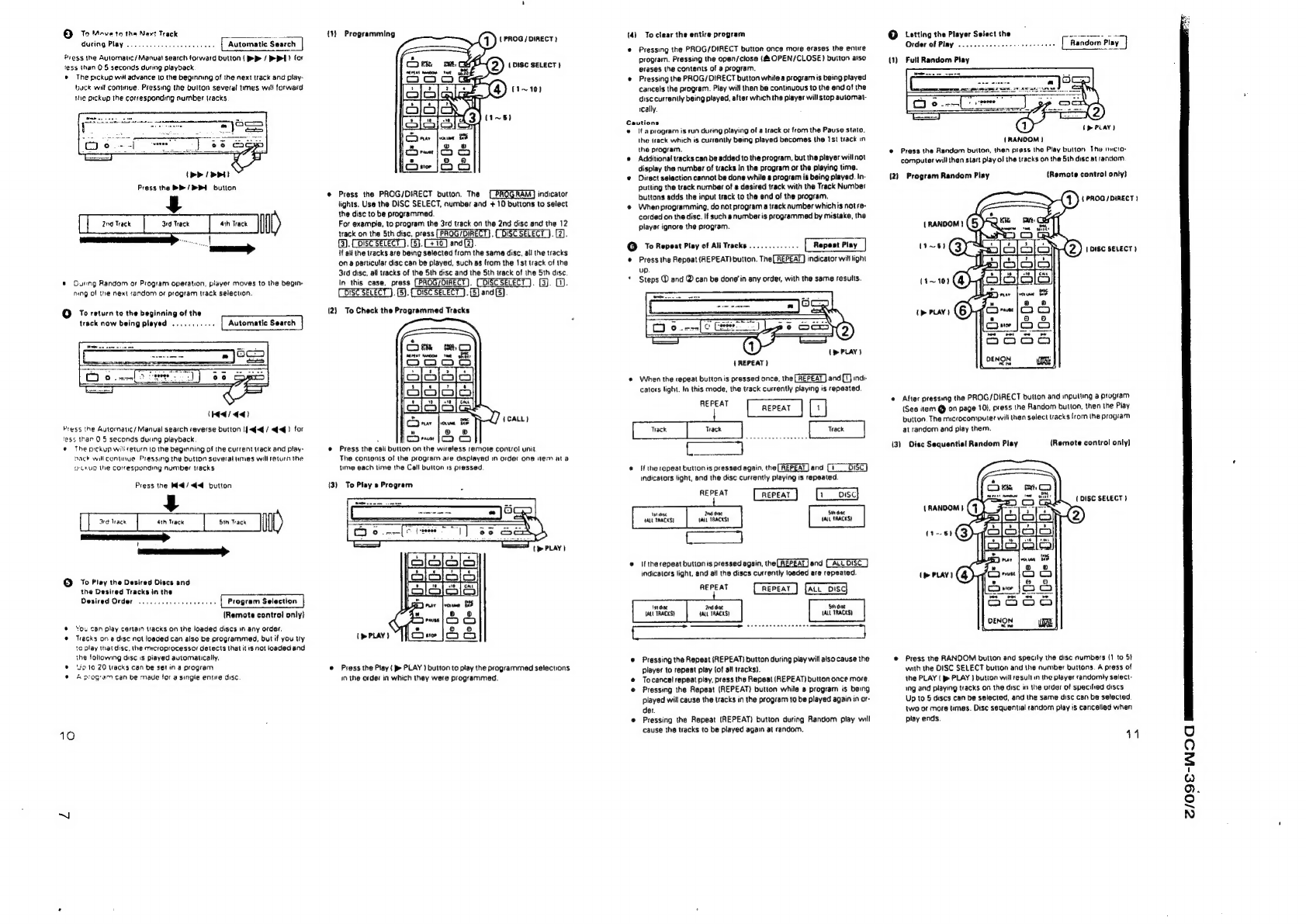
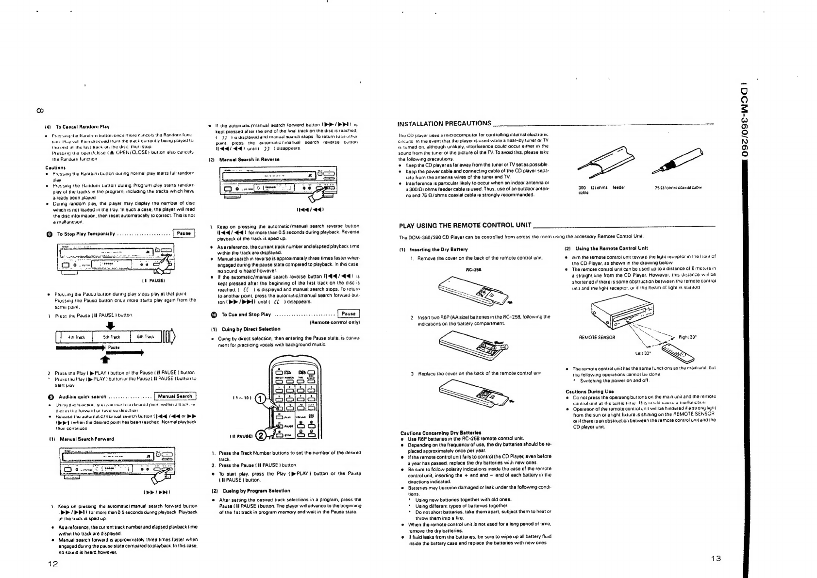
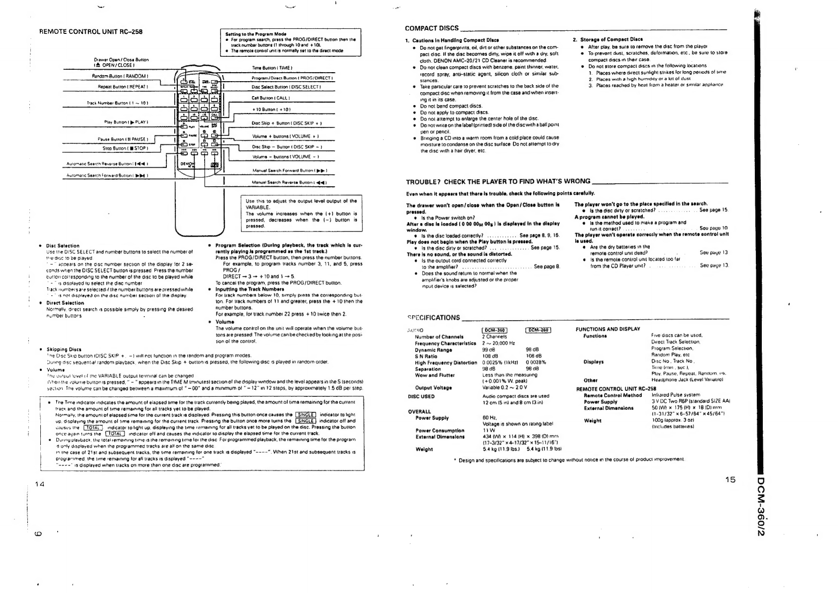
Denon DCM-360 User manual
Other Denon CD Player manuals

Denon
Denon DCM27 - DCM 27 CD User guide

Denon
Denon DCD-900NE User manual

Denon
Denon Dn-c620 - Dnc620 Professional Broadcast Cd... User manual

Denon
Denon DCD-510AE User manual

Denon
Denon DCM-290 User manual

Denon
Denon DCM-380 User manual

Denon
Denon DVD-1920 User manual

Denon
Denon DVD-3910 User manual

Denon
Denon DCD-1600NE User manual

Denon
Denon DND6000 - Dual DJ CD Player User manual

Denon
Denon DCM-460 User manual

Denon
Denon DCD-201SA User manual

Denon
Denon DCD-1520AE User manual

Denon
Denon DVD-1930CI User manual

Denon
Denon DCD-500AE User manual

Denon
Denon DCD-1520AE User manual

Denon
Denon DCD-510AE User manual

Denon
Denon DCM-27 User manual

Denon
Denon DCD-900NE User manual

Denon
Denon DVD-2200 User manual