manuals.online logo
Brands
  1. Home
  2. •
  3. Brands
  4. •
  5. Denon
  6. •
  7. Home Theater System
  8. •
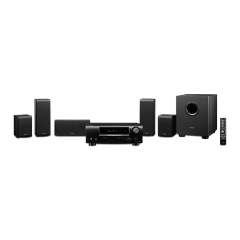
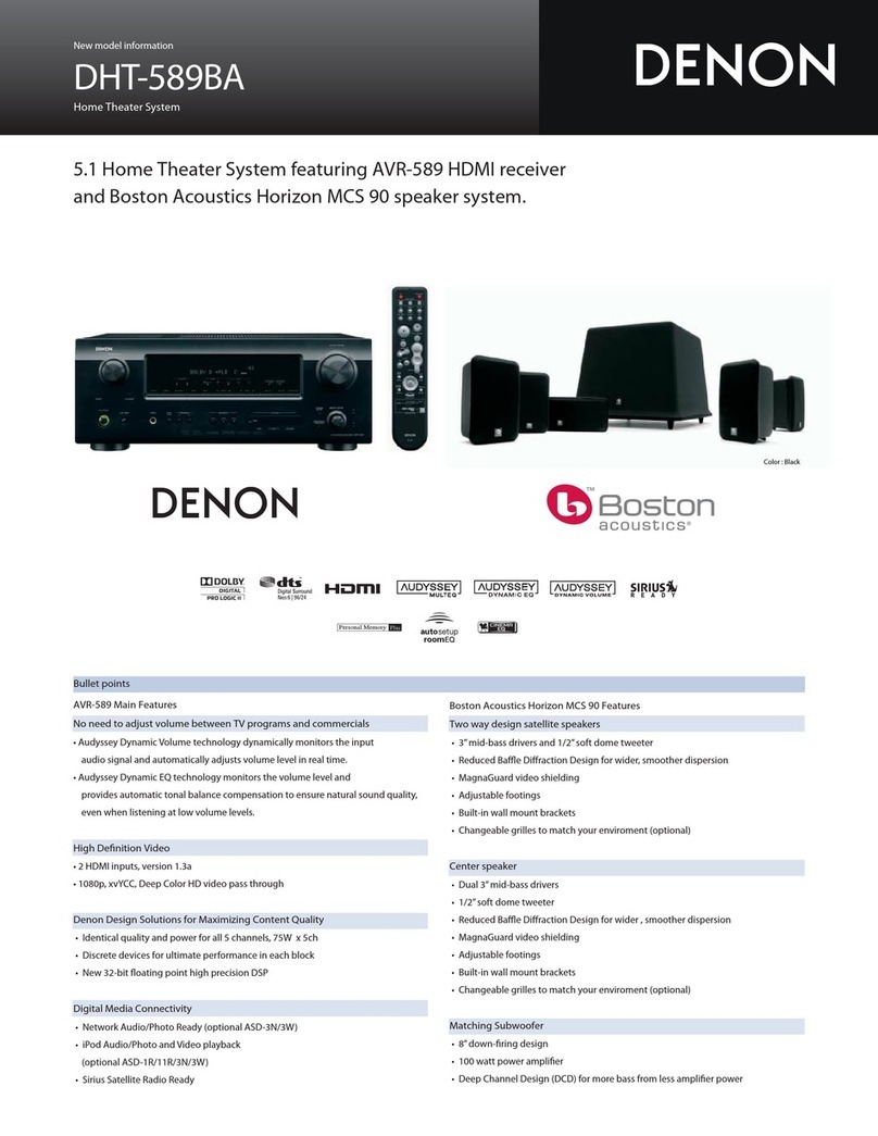
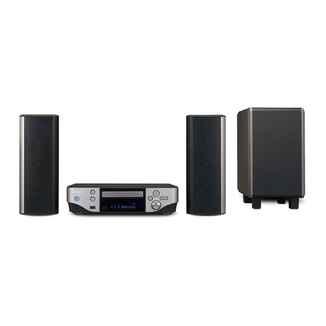
  9. Denon DHT-S416 User manual

Denon DHT-S416 User manual

Other manuals for DHT-S416

1

Other Denon Home Theater System manuals

Denon ADV-700 User manual

Denon

Denon ADV-700 User manual

Denon DHT-588BA User manual

Denon

Denon DHT-588BA User manual

Denon DHT-500SD User manual

Denon

Denon DHT-500SD User manual

Denon AVR 2807 - AV Receiver User manual

Denon

Denon AVR 2807 - AV Receiver User manual

Denon DRA-697CIHD - Premier AM/FM Stereo User manual

Denon

Denon DRA-697CIHD - Premier AM/FM Stereo User manual

Denon S-302 Administrator guide

Denon

Denon S-302 Administrator guide

Denon DHT-683DVD User manual

Denon

Denon DHT-683DVD User manual

Denon S-102 User manual

Denon

Denon S-102 User manual

Denon DRA-697CI User manual

Denon

Denon DRA-697CI User manual

Denon AVP-A1HD User manual

Denon

Denon AVP-A1HD User manual

Denon DHT-FS3 User manual

Denon

Denon DHT-FS3 User manual

Denon S-102 User manual

Denon

Denon S-102 User manual

Denon S-302 User manual

Denon

Denon S-302 User manual

Denon S-302 - AV System User guide

Denon

Denon S-302 - AV System User guide

Denon DHT FS5 - X-SPACE Surround System Home Theater Speaker... User manual

Denon

Denon DHT FS5 - X-SPACE Surround System Home Theater Speaker... User manual

Denon S-301 User manual

Denon

Denon S-301 User manual

Denon DHT487DV - DHT Home Theater System User manual

Denon

Denon DHT487DV - DHT Home Theater System User manual

Denon DRA CX3 - Audiophile Stereo AM/FM Lifier User guide

Denon

Denon DRA CX3 - Audiophile Stereo AM/FM Lifier User guide

Denon S-302 User manual

Denon

Denon S-302 User manual

Denon DHT-488XP User manual

Denon

Denon DHT-488XP User manual

Denon S-302 - AV System Dimensions

Denon

Denon S-302 - AV System Dimensions

Denon S-32 User guide

Denon

Denon S-32 User guide

Denon S-102 User manual

Denon

Denon S-102 User manual

Denon DHT-S316 User manual

Denon

Denon DHT-S316 User manual

Popular Home Theater System manuals by other brands

Samsung HT-DL200 instruction manual

Samsung

Samsung HT-DL200 instruction manual

Samsung HT-ES6600 user manual

Samsung

Samsung HT-ES6600 user manual

Curtis DVD6010 instruction manual

Curtis

Curtis DVD6010 instruction manual

Philips MCD716/12 user manual

Philips

Philips MCD716/12 user manual

Sherwood ST-4108 operating instructions

Sherwood

Sherwood ST-4108 operating instructions

Philips HTS5520/12 quick start

Philips

Philips HTS5520/12 quick start

Sony BDV-T57 Notices and Licences

Sony

Sony BDV-T57 Notices and Licences

LG HT503PHW owner's manual

LG

LG HT503PHW owner's manual

Samsung HT-ES4200K user manual

Samsung

Samsung HT-ES4200K user manual

Samsung HT-P10 instruction manual

Samsung

Samsung HT-P10 instruction manual

Philips HTS5131 User manaul

Philips

Philips HTS5131 User manaul

Goodmans GDVD19SWS user manual

Goodmans

Goodmans GDVD19SWS user manual

Moxi media center user guide

Moxi

Moxi media center user guide

Samsung HT-EM35 user manual

Samsung

Samsung HT-EM35 user manual

Sony BDV-N990W installation guide

Sony

Sony BDV-N990W installation guide

Manta GK-500 user manual

Manta

Manta GK-500 user manual

Sharp SBW800 user manual

Sharp

Sharp SBW800 user manual

Philips HTS3541 user manual

Philips

Philips HTS3541 user manual

manuals.online logo
manuals.online logoBrands
  • About & Mission
  • Contact us
  • Privacy Policy
  • Terms and Conditions

Copyright 2025 Manuals.Online. All Rights Reserved.

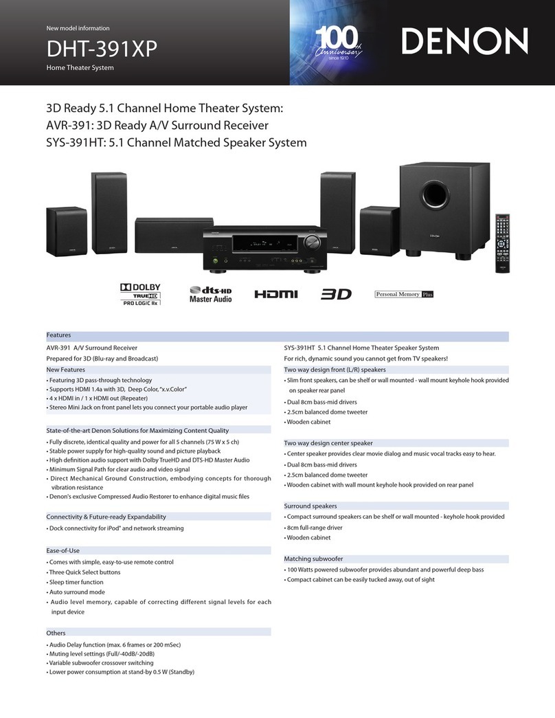
Service Manual
HOME THEATER SYSTEM
DHT-S416 Click here!
On-line service parts list
https://dmedia.soundunited.com/documents/details/27546
ONLINE PARTS LIST (P5)
WEB owner’s manual
EU: http://manuals.denon.com/DHTS416/EU/EN/index.php
Upload is planned for the time of a future press release.
BEFORE SERVICING THIS UNIT
ELECTRICAL
MECHANICAL
REPAIR INFORMATION
UPDATING
Ver. 1
Condential
•Forpurposesofimprovement,specicationsanddesignaresubjecttochangewithoutnotice.
•Pleaseusethisservicemanualwhenreferringtotheoperatinginstructionswithoutfail.
•Someillustrationsusedinthisservicemanualareslightlydifferentfromtheactualproduct.
Before Servicing
This Unit Electrical Mechanical Repair Information Updating
BEFORE SERVICING THIS UNIT
SAFETY PRECAUTIONS
NOTE FOR SCHEMATIC DIAGRAM
HANDLING THE SEMICONDUCTOR AND OPTICS
ONLINE PARTS LIST
Accessing the Parts List
Searching Part Numbers or Ref. Numbers
NOTE FOR PARTS LIST
SERIAL NUMBER
Serial Number Organization
SKU Code of this Unit
POST-SERVICE PRECAUTIONS
Initializing this Unit
2
Before Servicing
This Unit Electrical Mechanical Repair Information Updating
The following items should be checked for continued protection of the customer and the service technician.
Leakage current check
Before returning the set to the customer, be sure to carry out either (1) a leakage current check or (2) a line to chassis resistance check. If the leakage current exceeds 0.5 milliamps, or if the resistance from
chassis to either side of the power cord is less than 460 kohms, the set is defective.
Be sure to test for leakage current with the AC plug in both polarities, in addition, when the set's power is in each state (on, off and standby mode), if applicable.
CAUTION Please heed the following cautions and instructions during servic-
ing and inspection.
◎ Heed the cautions!
Cautions which are delicate in particular for servicing are labeled on the cabinets, the parts and the
chassis, etc. Be sure to heed these cautions and the cautions described in the handling instructions.
◎ Cautions concerning electric shock!
(1) An AC voltage is impressed on this set, so if you touch internal metal parts when the set is energized,
you may get an electric shock. Avoid getting an electric shock, by using an isolating transformer and
wearing gloves when servicing while the set is energized, or by unplugging the power cord when
replacing parts, for example.
(2) There are high voltage parts inside. Handle with extra care when the set is energized.
◎ Caution concerning disassembly and assembly!
Through great care is taken when parts were manufactured from sheet metal, there may be burrs on the
edges of parts. The burrs could cause injury if ngers are moved across them in some rare cases. Wear
gloves to protect your hands.
◎ Use only designated parts!
The set's parts have specic safety properties (re resistance, voltage resistance, etc.). Be sure to use
parts which have the same properties for replacement. The burrs have the same properties. In particular,
for the important safety parts that are indicated by the z mark on schematic diagrams and parts lists,
be sure to use the designated parts.
◎ Be sure to mount parts and arrange the wires as they were originally placed!
For safety seasons, some parts use tapes, tubes or other insulating materials, and some parts are
mounted away from the surface of printed circuit boards. Care should also be taken with the positions
of the wires by arranging them and using clamps to keep them away from heating and high voltage
parts, so be sure to set everything back as it was originally placed.
◎ Make a safety check after servicing!
Check that all screws, parts and wires removed or disconnected when servicing have been put back
in their original positions, check that no serviced parts have deteriorated the area around. Then make
an insulation check on the external metal connectors and between the blades of the power plug. And
otherwise check that safety is ensured.
(Insulation check procedure)
Unplug the power cord from the power outlet, disconnect the antenna, plugs, etc., and on the power.
Using a 500V insulation resistance tester, check that the insulation resistance value between the inplug
and the externally exposed metal parts (antenna terminal, headphones terminal, input terminal, etc.) is
1M Ω or greater. If it is less, the set must be inspected and repaired.
Many of the electric and the structural parts used in the set have special safety properties. In most
cases these properties are difcult to distinguish by sight, and the use of replacement parts with higher
ratings (rated power and withstand voltage) does not necessarily guarantee that safety performance
will be preserved. Parts with safety properties are indicated as shown below on the wiring diagrams and
the parts list in this service manual. Be sure to replace them with the parts which have the designated
part number.
(1) Schematic diagrams Indicated by the z mark.
(2) Parts lists Indicated by the z mark.
The use of parts other than the designated parts could cause electric shocks, res or other dangerous
situations.
CAUTION Concerning important safety parts
SAFETY PRECAUTIONS
3
Before Servicing
This Unit Electrical Mechanical Repair Information Updating
WARNING:
Parts indicated by the z mark have critical characteristics. Use ONLY replacement parts recommended
by the manufacturer.
CAUTION:
Before returning the set to the customer, be sure to carry out either (1) a leakage current check or (2)
a line to chassis resistance check. If the leakage current exceeds 0.5 milliamps, or if the resistance from
chassis to either side of the power cord is less than 460 kohms, the set is defective.
WARNING:
DO NOT return the set to the customer unless the problem is identied and remedied.
NOTICE:
(1) ALL RESISTANCE VALUES IN OHM. k=1,000 OHM / M=1,000,000 OHM
(2) ALL CAPACITANCE VALUES ARE EXPRESSED IN MICRO FARAD, UNLESS OTHERWISE INDICATED. P
INDICATES MICRO-MICRO FARAD. N INDICATES NANO FARAD.
(3) EACH VOLTAGE AND CURRENT ARE MEASURED AT NO SIGNAL INPUT CONDITION.
(4) CIRCUIT AND PARTS ARE SUBJECT TO CHANGE WITHOUT PRIOR NOTICE.
Electrostatic breakdown of the semi-conductors or optical pickup may occur due to a potential differ-
ence caused by electrostatic charge during unpacking or repair work.
1. Ground for Human Body
Be sure to wear a grounding band (1 M ohm) that is properly grounded to remove any static electricity
that may be charged on the body.
2. Ground for Workbench
Be sure to place a conductive sheet or copper plate with proper grounding (1 M ohm) on the workbench
or other surface, where the semi-conductors are to be placed. Because the static electricity charge
on clothing will not escape through the body grounding band, be careful to avoid contacting semi-
conductors with your clothing
<Incorrect>
CBA
Grounding Band
Conductive Sheet or
Copper Plate
1MΩ
1MΩ
<Correct>
CBA
NOTE FOR SCHEMATIC DIAGRAM
HANDLING THE SEMICONDUCTOR AND OPTICS
4
Before Servicing
This Unit Electrical Mechanical Repair Information Updating
ONLINE PARTS LIST
Accessing the Parts List
(1) Access from the Service Manual
・ Click the URL link on the cover of the service manual.
Examples of display
NOTE : If the web browser does not open automatically, copy the URL and paste it into the address bar
of the web browser and then press Enter.
(2) Accessing the Part List from the Model Asset Screen.
・ Display Model Asset from New SDI.
・ Click the section displayed as ▼ Link to Part Lists under the model name.
NOTE : If the ▼ Link to Parts List section is not displayed, download the parts table from the Asset list.
INTEGRATED NETWORK AV RECEIVER
AAA-AAAA
Service Manual
Click here!
On-line service parts list
https://dmedia.soundunited.com/documents/details/XXXXX
ONLINE PARTS LIST (P5)
WEB owner’s manual
NA: http://manuals.denon.com/AAAAAAA/NA/EN/index.php
EU: http://manuals.denon.com/AAAAAAA/EU/EN/index.php
AP: http://manuals.denon.com/AAAAAAA/AP/ZH/index.php
JP: http://manuals.denon.com/AAAAAAA/JP/JA/index.php
Upload is planned for the time of a future press release.
BEFORE SERVICING THIS UNIT
Ver. 1
All Assets Tasks Drafts Notifications Deactivated Archived Advanced Search Search Content
Search
0000 XxxxxXxxxx 32.2 Published XxxxxXxxxx 09-May-2019
A
sse
t
N
o
:
O
w
n
e
r
:
C
u
r
r
e
n
t
V
e
r
si
o
n
:
S
t
a
t
u
s:
P
u
b
l
i
sh
e
d
B
y:
P
u
b
l
i
sh
e
d
O
n
:
Bac
k
Additional Classification
Brand
Region AP - JAPAN, NA, E
U, AP - CHINA
Asset Type SDI
Category
XXXXXXXXXXXXXXXX
Description ▼Link to Parts List
XXXXXXXXXXXXXXXX
Version History
Version No. Type Created On
3
2
.
2
M
a
j
o
r
0
9
-
M
a
y
-
2
0
1
9
V
i
e
w
32.1 Major 23-Apr-2019 View
32.0 Major 07-Feb-2019 View
31.0 Major 07-Feb-2019 View
30.0 Major 24-Dec-2017 View
XXXXXXXXXX
(392.35 MB)

Download Pac kag
e
Edit Thi
s
Deactivat
e
Archi
ve
Denon
Searching Part Numbers or Ref. Numbers
You can search a Parts List for part numbers or Ref. numbers.
(1) Enter the part number or Ref. number in the search window of the Parts List, and press the search
button.
(2) The search results are displayed.
The name of the sheet in which the search part is used and the part’s line are displayed.
(3) Next, click the "Sheet" section of the search results.
Create Public URL
S
e
a
r
c
h
R
e
s
u
l
t
(
s
)
F
o
u
n
d
-
1
0
1SMPS D9001 943203500730S DIODE, RECTIFIER,
AXIAL CVD1N4007SL 1
2SMPS D9002 943203500730S DIODE, RECTIFIER,
AXIAL CVD1N4007SL 1
3SMPS D9003 943203500730S DIODE, RECTIFIER,
AXIAL CVD1N4007SL 1
4SMPS D9004 943203500730S DIODE, RECTIFIER,
AXIAL CVD1N4007SL 1
5SMPS D9005 943203500730S DIODE, RECTIFIER,
AXIAL CVD1N4007SL 1
6SMPS D9008 943203500730S DIODE, RECTIFIER,
AXIAL CVD1N4007SL 1
7FRONT D6005 943203500730S DIODE, RECTIFIER,
AXIAL CVD1N4007SL 1
8FRONT D6006 943203500730S DIODE, RECTIFIER,
AXIAL CVD1N4007SL 1
9FRONT D6007 943203500730S DIODE, RECTIFIER,
AXIAL CVD1N4007SL 1
10 FRONT D6018 943203500730S DIODE, RECTIFIER,
AXIAL CVD1N4007SL 1
FRONT INPUT VIDEO F.CNT S.CNT DIGITAL 943203500730S
21095 Super Administrator 1.2 Published Kazuhiro Nakai 23-Jul-2019
A
sse
t
N
o
:
O
w
n
e
r
:
C
u
r
r
e
n
t
V
e
r
si
o
n
:
S
t
a
t
u
s:
P
u
b
l
i
sh
e
d
B
y:
P
u
b
l
i
sh
e
d
O
n
:
SR6014 Parts List (525.24 KB)

Download Package
1. Parts indicated by "nsp" on this table cannot be supplied.
2. When ordering a part, make a clear distinction between "1" and "I" (i) to avoid mis-supplying.
3. A part ordered without specifying its part number can not be supplied.
4. Part indicated by "@" mark is not illustrated in the exploded and packaging view.
WARNING: Parts indicated by the z mark have critical characteristics. Use ONLY replacement parts
recommended by the manufacturer.
NOTE FOR PARTS LIST
5
Before Servicing
This Unit Electrical Mechanical Repair Information Updating
Product SKU SKU Code
DHTS416BKE2 DBHJ
SERIAL NUMBER
Serial Number Organization
The 13-digit serial number that contains the code of the manufacturing plant and the manufacturing
date.
Cumulative
serial number
SKU code Month
(01 ~ 12) The last
2digit of year
13 digits
SKU Code of this Unit
6
Before Servicing
This Unit Electrical Mechanical Repair Information Updating
Make sure to initialize this unit after replacing the microcomputer or any peripheral equipment, or the
PCB.
1. While the power is On, hold down buttons "RESET" for at least 5 seconds.
(2) All LEDs light up three times after initialization.
LED1 LED2 LED3 LED4
Step 1 Red Red Red Red
Step 2 Red Red Red Red
Step 3 Red Red Red Red
(3) Wait six seconds before turning on the power again.
Initializing this Unit
POST-SERVICE PRECAUTIONS
7
Before Servicing
This Unit Electrical Mechanical Repair Information Updating
ELECTRICAL
SCHEMATIC DIAGRAMS
SCH01 Bar MAIN SYS POWER
SCH02 Bar MAIN MCU
SCH03 Bar MAIN USB IR ADC
SCH04 Bar MAIN HDMI OUT
SCH05 Bar MAIN STW339
SCH06 Bar MAIN CONNECTOR
SCH07 Bar KEY IA3S4
SCH08 Bar KEY KEY
SCH09 Bar Module MT8516 POWER
SCH10 Bar Module MT8516 BASEBAND
SCH11 Bar Module MT6392_PMIC
SCH12 Bar Module MT8516 MEMORY PCDDR3L
SCH13 Bar Module MT8516 XTAL
SCH14 Bar Module MT7668
SCH15 Bar Module eMMC NAND
SCH16 Bar Module MT8516 DMIC
SCH17 Bar Module CONNECTOR
SCH18 Bar SMPS
SCH19 Subwoofer POWER&AUDIO Power Supply
SCH20 Subwoofer POWER&AUDIO Wireless
SCH21 Subwoofer Module AMP Circuit
SCH22 Subwoofer Module AU
PRINTED CIRCUIT BOARDS
For Sound bar : MAIN, AU_OPT, KEY, SMPS
For Subwoofer : MAIN(SUB)
BLOCK DIAGRAM and POWER DIAGRAM for
Sound bar
BLOCK DIAGRAM and POWER DIAGRAM for
Subwoofer
CURRENT DIAGRAM for Sound bar
CURRENT DIAGRAM for Network standby
CURRENT DIAGRAM for Deep standby
CURRENT DIAGRAM for Subwoofer
WIRING DIAGRAM for Sound bar
WIRING DIAGRAM for Subwoofer
Remote Code Table
8
Before Servicing
This Unit Electrical Mechanical Repair Information Updating
SCH01 Bar MAIN SYS POWER
SCHEMATIC DIAGRAMS
POWER IN DCDC 3V9
DCDC 5V1 DCDC 3V3
VOUT=0.6*(1+R10/R14)=5.1v
Vin
:
2.5V<Vin<5.5V
Vout=0.6*(1+R11/R12)=3.32V
01UBUCK1-SY80882
VOUT=0.6*(1+R3/R6)=3.93v
USB 5V
SYS_3V3
STB_3V3
STB5V1
POWER_15V
STB5V1
AMP_VCC
STB3V9
POWER_15V
POWER_15V
SYS_3V3
STB_3V3
USB_5V
STB5V1
FR+
FR-
MT8516_POWER
OTG_PWR_EN
SYS_POWER_CTL
R6
18K/1%
R258
10K
R4 NC/1K
U5
JW7115-2
VIN
5
FLG 3
EN
4
VOUT 1
GND 2
R11
68K/1%
C8
NC/0.1uF/16V/X7R
U1
SY8120I
BST
1
GND 2
FB 3
EN
4
VIN
5
SW 6
R10
150K/1%
R14
20K/1%
C3
10uF/25V/X5R
R12
15K/1%
R13
100K
U3
SY8120I
BST
1
GND 2
FB 3
EN
4
VIN
5
SW 6
R1 0Ω/0603
C10
22pF/50V/NP0
R9
390K
C12
10UF/6.3V/X5R
R5
100K
+
NC/47uF/6.3V
CE2
L3 2.2uH/2.1A
R7 0Ω/0402
R17 1K
C16
10uF/10V/X5R
C13
10uF/25V/X5R
C2
220pF/50V/NP0
R2
390K
C14
100nF/25V/X5R
C18
NC/0.1uF/16V/X7R
C9 0.1uF/16V/X7R
U2
SY8088I
EN
1
VIN
4LX 3
VFB 5
GND
2
C19
0.1uF/16V/X7R
C5
10UF/6.3V/X5R
C15
10uF/10V/X5R
C4
100nF/25V/X5R
R8 0Ω/0603
R18
NC/10K
C7
100nF/25V/X5R
L2 3.3uH/3.4A
R16 1K
C6
10UF/6.3V/X5R
R15
NC/10K
C20
0.1uF/16V/X7R
R3
100K/1%
U4
JW7115-2
VIN
5
FLG 3
EN
4
VOUT 1
GND 2
XP1
6PIN/2.5mm
11
22
33
44
55
66
C11
220pF/50V/NP0
L1 4.7uH/2A
C17
4.7UF/10V/X5R
C1 0.1uF/16V/X7R
9
Before Servicing
This Unit Electrical Mechanical Repair Information Updating
SCH02 Bar MAIN MCU
MCU
OscillatorResetUpgrade
Print log
MCU_RST
YO
YI
SWDIO
IR_IN
LED_SDA
MCU_CEC
YO
MCU_RST
SWCLK
SWDIO
SWCLK
UART2_TX
UART2_RX
MCU_RX
MCU_TX
MCU_CEC
YI
UART2_RX
UART2_TX
MCU_3V3
MCU_3V3
MCU_3V3
MCU_3V3
MCU_3V3
MCU_3V3
MCU_3V3
STB_3V3 MCU_3V3
MCU_3V3
MCU_3V3
IR_IN
MT8516_TX
MT8516_RX
MT8516_POWER
MCU_INT
KEY_POWER
HDMI_CEC
WAKEUP
HDMI_SCL
HDMI_SDA
HPLG
C32
NC/4.7UF
U6
STM32F071C8T6
VBAT
1
PC13
2
PC14
3
PC15T
4
PF0
5
PF1
6
NRST
7
VSSA
8
VDDA
9
PA0
10
PA1
11
PA2
12
PA3
13
PA4
14
PA5
15
PA6
16
VDD
24
VSS
23
PB11
22
PB10
21
PB2
20
PB1
19
PB0
18
PA7
17
PA11 3 2
PA10 3 1
PA9 30
PA8 29
PB15 2 8
PB14 2 7
PB13 2 6
PB12 2 5
PA12 3 3
PA13 3 4
VSS 35
VDDIO236
VDD 48
VSS47
PB946
PB845
BOOT0 44
PB743
PB642
PB541
PB440
PB339
PA15 38
PA14 37
C21
10UF/6.3V/X5R
C23 0.1uF/16V/X7R
C28
0.1uF/16V/X7R
R25 0Ω/0402
R145
0
TP1
C24 0.1uF/16V/X7R
R28 NC/1M
R29
10K
R21 0Ω/0603
R22 0Ω/0402
C22 0.1uF/16V/X7R
TP3
R32 1K
TP4
C27 0.1uF/16V/X7R
R2450Ω/0402
C29
NC/20pF/50V/NP0
C25 0.1uF/16V/X7R
R23 0Ω/0402
C26 NC/10uF/6.3V/X5R
TP8
NC/12MHz +- 20ppm
Y1
1
2
3
4
R19
4.7K
Q13 N_2SK3018
G
D S
C30
NC/20pF/50V/NP0
TP2
XP8
4PIN/1.25mm
11
22
33
44
GND
5GND
6
TP9
R20
NC/4.7K
R27 0Ω/0402
C31
0.1uF/16V/X7R
XP2
4PIN/1.25mm
11
22
33
44
GND
5GND
6
R244
27K
10
Before Servicing

This Unit Electrical Mechanical Repair Information Updating