Denon S-302 User manual

DENON
DVD HOME ENTERTAINMENT SYSTEM
5-302
Owner's Manual
Manuel de l'Utilisateur
Manual del usuario
Graphical
User
'nterface
mtm,
Use
this
manual
in
combination with
the
operating
guide
displayed
on
the
GUI
screen.
GUI
Menu
Operations
(&page
16)
GUI
Menu
Map
(&page
17)
Language
(&page
18)
Remote
Control
Unit
0erations 1Gr'page
40)
'iSM'!E
Utilisez
ce
manuel
en
mime
temps
que
Ie
guide
d'utilisation
afliche
sur
I'ecran
GUI
(Interface graphiquel.
Utilisation
du
menu
de
l'interfacegraphique
(G"'page
16)
Carte
du
menu(&
page
17)
Langue
(&
page
18)
Fonctionnement
de
la
tlHecommande
(&page
40)
UiHi.[.j
Utilice
este
manual
conjuntamente
con
la
guia
de
uso
que
aparece
en
la
pantalla
GUI.
Operaciones
del
menu
GUI
(&pagina
16)
Mapa
del
menu
de
la
GUI
(&pagina
17)
Idioma
(&pagina
18)
Operaciones
con
el
mando
adistancia
(&
pagina
40)

ENGLISH FRANCAIS ESPANOL
oSAFETY PRECAUTIONS SAFETY INSTRUCTIONS
13.
Power-Cord Protection -Power-supply cords should
be
routed
so
that they
are not likely to be walked on or pinched by
items
placed upon or against
them, paying particular attention
to
cords at plugs, convenience receptacles,
and the point where they exit from the product.
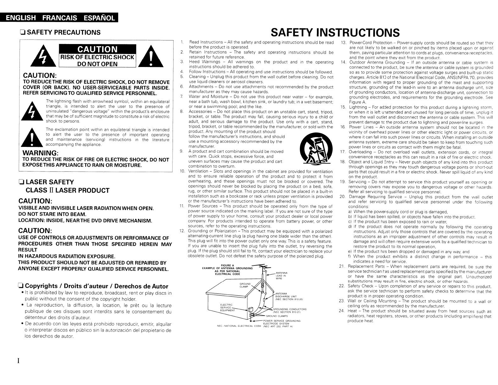
14.
Outdoor Antenna Grounding -If
an
outside antenna or cable system
is
connected
to
the product, be sure the antenna or cable system is grounded
so
as
to provide some protection against voltage surges
and
built-up static
charges. Article 810 of the National Electrical Code, ANSI/NFPA 70, provides
information
with
regard
to
proper grounding of the mast
and
supporting
structure, grounding
of
the lead-in wire
to
an
antenna discharge unit. size
of
grounding conductors, location
of
antenna-discharge unit. connection to
grounding electrodes, and requirements for
the
grounding electrode.
See
Figure
A.
15
Lightning -
For
added protection for this product during alightning storm,
or
when
it is left unattended and unused for long periods of time, unplug it
from the wall outlet and disconnect the antenna or cable system. This will
prevent damage
to
the product due
to
lightning and power-line surges.
16.
Power Lines -An outside antenna system should not
be
located
In
he
vicinity of overhead power lines or other electric light or power cirCUits, or
where
it can fall into such
power
lines or circuits. When installing
an
outside
antenna system, extreme care should
be
taken to keep from touching such
power lines or CIrcuits
as
contact
with
them
might
be
fatal.
17.
Overloading -
Do
not overload wall outlets, extension cords,
or
Integral
convenience receptacles
as
this can result
in
arisk of fire or electric shock.
18.
Object and Liquid Entry -Never push objects
of
any kind into this product
through openings
as
they may touch dangerous voltage points
or
short-out
parts that could result
in
afire or electric shock. Never spill liquid
of
any kind
on the product.
19. Servicing -Do not attempt
to
service this product yourself
as
opening or
removing covers may expose you
to
dangerous voltage or other hazards.
Refer all servicing to qualified service personnel.
20. Damage ReqUiring Service -Unplug this product from the wall outlet
and refer servicing to qualified service personnel under the following
conditions:
a)
When the power-supply cord or plug
is
damaged,
b)
If liquid has been spilled, or objects have fallen into the product.
c)
If the product has been exposed
to
rain or water,
dl If the product does not operate normally by following the operating
instructions. Adjust only those controls that are covered by the operating
instructions
as
an
improper adjustment of other controls may result
in
damage and will often require extensive
work
by aqualified technician to
restore the product
to
its normal operation,
e)
If the product has been dropped or damaged
in
any
way,
and
f)
When
the product exhibits adistinct change
in
performance -this
indicates aneed for service.
21
Replacement Parts -When replacement parts are required, be sure the
service technician has used replacement parts specified by the manufacturer
or have the same characteristics
as
the original part. Unauthorized
substitutions may result
in
fire, electric shock,
or
other hazards.
22. Safety Check -Upon completion of any service or repairs
to
thiS product,
ask the service technician to perform safety checks to determine that the
product
is
in
proper operating condition.
23.
Wall or Ceiling Mounting -The product should be mounted to awall or
ceiling only
as
recommended by the manufacturer.
24.
Heat -The product should
be
situated away from heat sources such
as
radiators, heat registers, stoves, or other products (including ampliflersl that
produce heat.
ANTENNA
LEAD
IN
WIRE
ANTENNA
DISCHARGE UNIT
(NEG SECTION 810·201
ELECTRIC
SERVICE
EQUIPMENT
FIGURE A
EXAMPLE
OF
ANTENNA
GROUNDING
AS PER
NATIONAL
ELECTRICAL
coDe
2
3
4.
5.
1.
__
POWER SERVICE GROUNDING
ELECTRODE
SYSTEM
NEC·
NATIONAL
ELECTRICAL
CODE
(NEG ART 250. PART
HI
8
6.
7
9
Read
Instructions -All the safety and operating instructions should be read
before the product
is
operated.
Retain Instructions -The safety and operating instructions should be
retained for future reference.
Heed Warnings -All warnings on the product and
in
the operating
instructions should
be
adhered to.
Follow Instructions -All operating and use instructions should
be
followed
Cleaning -Unplug this product from the wall outlet before cleaning. Do not
use liquid cleaners or aerosol cleaners.
Attachments -Do not use attachments not recommended by the product
manufacturer
as
they may cause hazards.
Water and Moisture -Do not use this product near water -for example,
near abath tub, wash bowl, kitchen sink, or laundry tub;
in
a
wet
basement;
or near a
swimming
pool; and the like.
Accessories -Do not place this product on
an
unstable cart, stand, tripod,
bracket. or table. The product may fall, causing serious injury to achild or
adult. and serious damage to the product. Use only
with
acart, stand,
tripod, bracket. or table recommended by the manufacturer, or sold
with
the
product. Any mounting of the product should
follow the manufacturer's instructions, and should
use amounting accessory recommended by the
manufacturer.
Aproduct and cart combination should be moved
with care. Quick stops, excessive force, and
uneven surfaces may cause the product and cart
combination
to
overturn.
10.
Ventilation -Slots and openings
in
the cabinet are provided for ventilation
and to ensure reliable operation of the product and to protect it from
overheating, and these openings
must
not be blocked or covered. The
openings should never be blocked by placing the product on abed, sofa,
rug, or other similar surface. This product should not
be
placed
in
abuilt-in
installation such
as
abookcase or rack unless proper ventilation
is
provided
or the manufacturer's instructions have been adhered to.
11.
Power Sources -This product should be operated only from the type of
power source indicated on the marking label. If you are not sure of the type
of power supply
to
your home, consult your product dealer or local power
company.
For
products Intended to operate from battery power, or other
sources, refer to the operating instructions.
12.
Grounding or Polarization -This product may be equipped with apolarized
alternating-current line plug
la
plug having one blade wider than the otherl.
This plug will fit into the power outlet only one way. This
is
asafety feature.
If you are unable
to
insert the plug fully into the outlet, try reversing the
plug. If the plug should still fail
to
fit, contact your electrician to replace your
obsolete outlet. Do not defeat the safety purpose of the polarized plug.
The lightning flash
with
arrowhead symbol,
within
an
equilateral
triangle, is intended to alert the user
to
the presence
of
uninsulated "dangerous voltage"
within
the product's enclosure
that
may be of sufficient magnitude to constitute arisk
of
electric
shock
to
persons.
The exclamation point within
an
equilateral triangle
is
intended
to
alert the user to the presence of important operating
and maintenance (servicing) instructions
in
the literature
accompanying the appliance.
oLASER SAFETY
CLASS n
LASER
PRODUCT
CAUTION:
VISIBLE
AND
INVISIBLE LASER RADIATION WHEN OPEN.
DO
NOT
STARE INTO BEAM.
LOCATION: INSIDE, NEARTHE DVD DRIVE MECHANISM.
WARNING:
TO REDUCETHE RISK
OF
FIRE
OR
ELECTRIC SHOCK, DO
NOT
EXPOSETHISAPPLIANCETO RAIN
OR
MOISTURE.
CAUTION:
TO REDUCETHE RISK OF ELECTRIC SHOCK, DO NOT REMOVE
COVER (OR BACK).
NO
USER-SERVICEABLE
PARTS
INSIDE.
REFER
SERVICING TO QUALIFIED SERVICE PERSONNEL.
CAUTION:
USE OF CONTROLS
OR
ADJUSTMENTS
OR
PERFORMANCE
OF
PROCEDURES OTHER THAN THOSE SPECIFIED HEREIN MAY
RESULT
IN
HAZARDOUS
RADIATION EXPOSURE.
THIS PRODUCT SHOULD NOT
BE
ADJUSTED OR REPAIRED
BY
ANYONE EXCEPT PROPERLY QUALIFIED SERVICE PERSONNEL.
oCopyrights IOroits d'auteur IOerechos de Autor
•
It
is
prohibited
by
law
to
reproduce,
broadcast.
rent
or
play
discs
in
public
without
the
consent
of
the
copyright
holder.
•La
reproduction,
la
diffusion,
la
location,
Ie
pret
ou
la
lecture
publique
de
ces
disques
sont
interdits
sans
Ie
consentement
du
detenteur
des
droits
d'auteur.
•
De
acuerdo
con
las
leyes
esta
prohibido
reproducir,
emitir,
alquilar
o
interpretar
discos
en
publico
sin
la
autorizaci6n
del
propietario
de
los
derechos
de
autor.
I

FCC
Information (For
US
customers)
1.
COMPLIANCE INFORMATION
Product Name: DVD
Home
Entertainment System
Model Number:
5-302
This product contains
FCC
10:
BV2- MPGBR052.
This
product complies with
Part
15
of the
FCC
Rules. Operation
is
subject to the following
two
conditions:
(l)
this
product may not cause harmful interference, and
(2)
this product must accept
any
interference received, including
interference that may cause undesired operation.
Denon Electronics
(USA),
LLC
100
Corporate Drive, Marwah,
NJ
07430-2041
Tel.
201-762-6500 (Main)
2.
IMPORTANT NOTICE: DO NOT
MODIFY
THIS PRODUCT
This
product, when installed
as
indicated
in
the instructions contained
in
this manual, meets
FCC
requirements.
Modification not expressly approved by DENON may void your authority. granted by the
FCC.
to use the product.
3.
CAUTION
•
To
comply with
FCC
RF
exposure compliance requirement, separation distance of at least
20
cm must
be
maintained between the antenna of this product and
all
persons.
•
This
product and its antenna must not
be
co-located or operating
in
conjunction with any other antenna or
transmitter.
4. NOTE
This product
has
been tested and found to comply with the limits for a
Class
B digital device, pursuant to
Part
15
of the
FCC
Rules. These limits
are
designed to provide reasonable protection against harmful interference
in
a
residential installation.
This
product generates, uses and
can
radiate radio frequency energy
and,
if not installed and used
in
accordance
with the instructions, may cause harmful interference to radio communications. However, there
is
no
guarantee
that interference will not occur
in
aparticular installation. If this product does cause harmful interference to radio or
television reception, which
can
be
determined by turning the product
OFF
and
ON,
the user
is
encouraged to
try
to
correct the interference by one or more of the following measures:
•Reorient or relocate the receiving antenna.
•Increase the separation between the equipment and receiver.
•Connect the product into
an
outlet on acircuit different from that to which the receiver
is
connected.
•Consult the local retailer authorized to distribute this type of product or
an
experienced radiorrv technician for
help.
ESPANOL FRANCAIS ENGLISH
IC
Information (For Canadian customers)
1.
PRODUCT
This product contains
IC
6963A-MPGBR052.
This product complies with
RSS-210
of Industry
Canada.
Operation
is
subject to the following
two
conditions:
(l)
this product may not cause harmful interference, and
(2)
this product must accept any interference received,
including interference that may cause undesired operation.
This Class Bdigital apparatus complies
with
Canadian ICES-003.
APPAREIL
Cet appareil contiens
IC
6963A- MPGBR052.
Cet appareil est conforme a
la
norme
CNR-21O
du
Canada.
L:utilisation
de
ce
dispositif est autorisee seulement
aux deux conditions suivantes :(1)
il
ne doit
pas
produire de brouillage, et
12)
I'utilisateur
du
dispositif doit etre
pret aaccepter tout brouillage radioelectrique
re<;u,
meme
si
ce
brouillage est susceptible de compromettre
Ie
fonctionnement du dispositif.
Cet appareil numerique
de
la
c1asse
Best
conforme a
la
norme NMB-003
du
Canada.
2. CAUTION
To
reduce potential radio interference to other users, the antenna type and its
gain
should
be
so chosen that the
equivalent isotropically radiated power (e.i.r.p.)
is
not more than that permitted for successful communication.
ATTENTION
Atin
de
reduire
Ie
risque d'interference aux autres utilisateurs.
il
faut choisir
Ie
type d'antenne
et
son
gain
de
fa<;on
a
ce
que
la
puissance isotrope rayonnee equivalente (p.i.r.e.) ne soit
pas
superieure
au
niveau requis pour I'obtention
d'une communication satisfaisante.
II

ENGLISH FRANCAIS ESPANOL
oNOTE ON USE IOBSERVATIONS RELATIVES AL'UTILISATION
•Do
not
let foreign objects into the unit.
•Ne pas laisser des objets etrangers dans
I'apparei!.
•No deje objetos extranos dentro del
equlpo.
•Keep the unit free from moisture, water,
and dust.
•Proteger !'appareil contre I'humidite, I'eau
et
la
poussiere.
•Mantenga el equipo libre de humedad,
f-------------------j
agua ypolvo.
•Avoid high temperatures.
Allow for sufficient heat dispersion when
installed
in
arack.
•Eviter des temperatures elevees.
Tanir comp ed'une dispersion de chaleur
suffisante lars
de
I'installation sur una
etagere.
•Evite altas temperatures.
Permits
la
suficiente dispersi6n del calor
cuando esta instalado en
la
consola.
•Never disassemble or modify the unit in
any way.
•Ne jamais
demonter
au modifier I'appareil
d'une
maniare ou d'une autre.
•Nunea desarme 0modifique
el
equipo de
nlnguna manera.
•Do
not
let insecticides, benzene, and
thinner come
in
contact
with
the unit.
•Ne pas
menre
en contact des insecticides,
du benzene et un diluant avec rappareil.
•No permita el contacto de insecticidas,
gasolina ydiluyentes con
el
equipo.
I I \
m
~I\\~I\
,
=~
, ,
;a.'t-.."
r
d
...
~....,.
b
"(For apparatuses
with
ventilation holes)
•Do
not
obs ruet the ventilation holes.
•Ne pas obstruer les trous d'aeration.
•
No
obstruya los orificios de ventilacion.
•Handle the power cord carefully.
Hold the plug when unplugging the cord.
•Manipuler
Ie
cordon d'alimentation avec
precaution.
Tenir
la
prise lars du debranchement du
cordon.
•ManeJe
el
cordon de energfa con cuidado.
Sostenga el
endlufe
cuando deseoneete el
cordon de energia.
1-----------------
.Unplug the
power
cord
when
not
using the
unit for long periods of time.
•Debrancher
Ie
cordon d'alimentation
lorsque I'appareil n'est
pas
utilise pendant
de longues periodes.
•Oesconecte
el
cord6n
de
energia cuando
no utilice el equipo par mucho tiampo.
ill

Contents
IConnections I
Preparations
..
·9
Cables Used for Connections·
·9
Video Conversion Function
..
10
Connecting
the
System·
10.11
Connecting
the
Monitor.. . .
..
·11
Connecting Equipment
with
HDMI
connectors .
12
Connecting
the
Playback Components
12
Control Dock for iPod·
..·
12
Apple iPod Dock.. .
·13
TV
Tuner
·13
Satellite Receiver..
..
·13
Connections
to
Other
Devices
..·
..
··13
USB
Port ..13
Antenna Terminals
14
External Controller
14
Network Audio· ..·15
Once Connections are Completed ·
15
IPlayback I
·32
··32
..
32
··33
33
....
·31
..
·31
·31
31
..
31.32
Playing Still Picture Files (JPEG
fonnat)
·
..
· · 28
Creating
JPEG
Files Compatible on the S-302 ·
·..
..·28
Playing
JPEG
Files..
..
29
Playing Picture CD/Fujicolor
CD
·29
Enjoying Surround Sound
..
29
Set the Input
Mode·
..
··29
Selecting Surround Mode ......30
Set the Surround Parameter ·
..
·30
Playing Dolby Digital/DTS Multi-Channel Sources
(Digital input only) .
Playing Dolby Digital/PCM/Analog 2-Channel Sources
Listening
in
the Dolby Headphone
Mode
..
Listening
to
Radio Broadcasts..
..
.
Tuning
in
Broadcast Stations
..
Naming the CurrentlyTuned
in
Broadcast Station and
Presetting it
..
Automatically Presetting FM Stations (Auto preset)
Listening
to
Preset Stations
..
iPod@ Playback
..
Listening to Music
.. ..
Viewing Still Pictures
(Only for iPods Equipped with the Photo Function) 33
Disconnecting the iPod.. .33
Playing
Network
Audio or USB
Memory
Devices 34. 35
Basic Operation..
..
35
Listening
to
Internet Radio..
..
·35. 36
Playing Files Stored on aComputer.. ·
36.37
Playing Files Stored on
USB
Memory
Devices.. ..37
Playing aPortable Audio.. .
..
37
27
..·27
..
16
..
·16
·······16
16
······16
·····16
....
17
·17
·18
···18
·
..
19
..
....
·19
..
·20
-22
···················22
22.
23
Example of
the
Display of
the
GUI
Mark
at
aTitle·....·
Example of Display
of
Default
Values
..
Examples of
GUI
Screen Displays
..
Example: Browse Menu
(Top
Menu) ·
Example: During Playback (NET/USB)
Cursor Position Display
Operations
..
·
..
·
..
·.
GUI
Menu
Map
SETUP .
DLanguage
fJ Video Setup
II
Audio
Setup·
II
Network
Setup
II
Others
m1Timer
Preparations··
·24
Turning the Power On
·24
Loading Discs
..
24
Input source
switching·
·24
Adjusting the
Master
Volume
·24
Playing a
DVD/Music
CD
Disc
..
25
Using the
Top
Menu/DVD Menu
(DVD
Video)·
......
·
..
· ·
..
·25
Switching the Audio Language. Subtitle Language and Angle
(DVD
Video)
···
..
·.·
······
..
· · ··26
Using the Playback Control Function
(DVD
Video) 26
Playing Frame by Frame
(DVD
Video) 26
Slow Playback (DVDVideo)
.. ..
26
Playing
in
the Zoom
Mode
(DVD
Video)
..
26
Playing Repeatedly <Repeat playback>
(DVDVideo/Music
CD)··
..
·
....
·
..
·
..
····
Playing
Tracks
in the Desired Order <Program>
(Music
CD)
..
Playing Random Order <Random playback>
(Music
CD)·
·
..
· .
Playing Music Files
Before Playing MP3
orWMA
Files
··
..
·
27
Creating MP3 and
WMA
Files Compatible
with
the S-302 27
Playing MP3
orWMA
Files·
··
·27. 28
I
GUI
Menu Opet'lltions
ISetup
..
2
2
....
·2
·
..
3
·
..
3
..
·4
· 4
· 4
.... 4
··5
..
5
..5
·
..
·5
·5
··5
·5
·6
6
6
·7
·····7
·8
Accessories·
Cautions on Handling
..
System Configuration
Cautions on Installation
Other Cautions
Discs
.
Discs usable on the S-302
Holding
Discs·
..
· · .
Loading Discs
Cautions on Loading Discs
Cautions on Handling···
Cautions on Storing Discs
..
Cleaning Discs
..
About the Remote Control
Unit
Inserting the Batteries
..
Operating Range
of
the Remote Control Unit
Part Names and Functions
··
..
Front
Panel
· ·
..
Display·
..
Rear
Panel·
..
· ·
..
Bottom
Panel
(Subwoofer)
Remote Control Unit .
[Getting Started
1

ENGLISH
u
/
Sub woofer
Unit
name:
DSW-S302
DVD surround receiver
Unit
name:
ADV-S302
~I
l~
Cautions on Handling
System Configuration
Speaker
Unit
name:
•Before turning
the
power switch
on
Check once again that
all
connections are correct
and
that there are
no problems
with
the connection cables.
•Power
is
supplied to some
of
the circuitry even when the unit is
set to the standby mode. When traveling or leaving home for long
periods
of
time,
be
sure to unplug the power cord from the
power
outlet.
•Sufficiently ventilate the place of installation
If the unit
is
left
in
aroom full
of
the smoke from cigarettes, etc., for
long periods of time. the surface
of
the optical pickup could get dirty,
in
which case
it
will not be able to read the signals properly.
•About condensation
If there
is
amajor difference
in
temperature between the inside
of
the unit
and
the surroundings, condensation (dewl may form on
the operating parts inside the unit, causing the unit not
to
operate
properly.
If this happens, let the unit sit for
an
hour or
two
with the power
turned off and wait until there
is
little difference
in
temperature
before using the unit.
•Cautions
on
using mobile phones
Using amobile phone near this unit may result
in
noise, If so, move
the mobile phone away from this unit when it
is
in
use.
•Moving
the
unit
Turn
off the power and unplug the power cord from the power
outlet.
Next, disconnect the connection cables to other system units before
moving the unit.
•Note that the illustrations
in
these instructions may differ
from
the
actual unit for explanation purposes.
<
Getting
Started
Accessories
<D
CD
Remote control
(RC-l0n)
. 1
@R6P/AA batteries 2
G)
System cable (D-SUB25P) (Cord length: Approx.
10
ft/3
m)
1
®Speaker cable (Cord length: Approx.
16
ft/5
m)
2
®Video cable (Cord length: Approx. 5ft/l.5
m)
.. ....
1
®
AM
loop antenna..
..
1
(j) FM indoor antenna 1
®Speaker stand........ ...... . 2
®Wall bracket 2
@Screw..................... . 4
(j})
Hex wrench.................
..
1
@
Rod
antenna for wireless LAN 1
@Anti slip pads............ .
..
4
@Owner's manual (with Quick setup
sheet)
1
@Warranty (for North America model
only)..
..
1
®Service station list.. 1
Thank you for purchasing this DENON product.
To
ensure proper
operation, please read these owner's manual carefully before using
the product.
After reading them, be sure to keep them for future reference.
Check that the following parts are supplied
with
the product.
....
40
..
·40
....·-40,
41
............................
End
of
this manual
Setting the preset
memory
function ....
Operating acomponent stored
in
the preset
memory
..
·
Setting the punch through function·
List of preset codes
IAdvanced Operation I
Setting
the
Sleep
Timer
...
38
Other Functions·· ······38
Adjusting theTone······· ·····38
Turning the Sound
Off
Ternporarily (Muting) ········38
Convenient Functions ·39
Personal
Memory
Plus Function ·39
Last Function
Memory·
·39
Backup
Memory·
··
..
···· ·
..
·
..
· ·
..
·
..
· · · ·39
Auto Power On ·
..
39
Resetting the Microprocessor
..
·39
I
Other
intormatlOn:·,·,·,,,
..
,:·;
·
..
:,
..
·
··
·
..
·
..
·
..
·
..
·
··42·::..
451
I
TtoUbieshOotmg,·:·,:·fl.:.·;,:····:·,·,
..
···,······
..
·····
..
· ·
..
,·::
..
,
·.:
46~49J
I
S~catiqns
..
:,·.···
..
··:::;···.·
..
·h : ,
50·1
I
2

ENGLISH
I
~
I3
i£
I
'"
I(')
Ia
~
II
~
I
i
I
If
II
I
(J)
I
'"
I
~
>----
i
-0
I"'
<:
C"
0>
"
"'"
«.,4Iiit·]~.
•
Be
sure to fasten the speaker cords to awall, etc., to
~
prevent people from tripping over them or otherwise '.
pulling
on
them accidentally, causing the speaker
systems to fall.
•
Be
sure to check for safety after installing the speaker systems.
Afterwards, perform safety inspections
at
regular intervals to
be
sure there
is
no
danger that the speaker systems will fall. DENON
will accept
no
responsibility for damages or accidents caused
by
inappropriate choice of the place ofinstallation or improperInstallation
procedures.
•Switching the input function when input terminals
are
not
connected.
Aclicking noise may
be
produced if the input function
is
switched
when nothing
is
connected to the input terminals. If this happens,
either turn down the VOLUME control knob
or
connect components
to the input terminals.
•When watching
TV
broadcasts with the S-302's power turned
on,
depending
on
the conditions of the
TV
broadcast's signals, striped
patterns may appear
on
the picture. This
is
not amalfunction of the
S-302
or the
TV.
Turn
the S-302's power off when watching
TV.
•Note that if amagnet or apiece of furniture or equipment using
magnets
is
placed nearby, interaction with the
S-302
could result
in
color blotching on the
TV.
-n·u·
•This product uses asemiconductor
laser.
To
ensure stable operation,
it
is
recommended to use the product indoors at atemperature of 5
°C
(41°F) -
35°C
(95
OF).
Wall
*
C)
~
*Note
(DSW-S302)
* *
~
Cautions on Installation
Note:
For
proper
heat
dispersal, do not install this unit in aconfined
space,
such
as abookcase or similar enclosure.
©
The
quality of the sound produced from the speaker
is
affected
by
the
size
and
type of the room,
as
well
as
by
the method of
installation. Consider the points listed below before installing the
speaker.
•
Placing
speakers
on
the same stand or shelf
as
the record player
could result
in
howling.
•If there
is
awall, glass
door,
etc., behind or to the sides of the
speakers, resonance
and
reflections
can
be
prevented
by
using a
thick curtain, etc.
•
The
speakers
are
of the shielded type. With some
TVs,
however,
placing the speakers near the
TV
could cause color blotching
on
the
TV's picture. If this happens, turn theTV's power off, move it
away,
wait 15 to 30 minutes, then turn theTV's power
back
on.
If the color
blotching persists, move the speakers further
away.
•Mount
on
awall sufficiently sturdy to bear the weight of the
speaker. Note that DENON will except
no
responsibility whatsoever
for damages
or
accidents caused
by
the speaker falling.
•
To
ensure safety,
have
aspecialist install the speakers
on
the wall.
•
Be
sure to fasten the speaker connection cables to the wall, etc.,
so
that you do not get your feet or hands caught
in
them, causing
the set to fall.
•
Place
the subwoofer
on
aflat floor to prevent accidents due to the
subwoofer tipping
over.
•
Do
not place arecord
player,
CD
player or other such device
on
top
of the subwoofer.
•
Do
not set the subwoofer with the baffle surface against the
floor.
Doing
so
will prevent
you
from achieving satisfactory sound
effects.
3

ENGLISH
Discs
Do
not touch the signal surface.
bH~o~ld~in~g~D~i~sc~s~~~~~~~~~~=1
•Set the disc
with
the labeled side facing up.
•Make sure the disc tray
is
fully open when inserting the disc.
•Place the discs flatly,
12
cm discs
in
the outer tray guide (Figure
1).
8
cm discs
in
the inner tray guide (Figure
2).
•"STOP"
is
displayed if adisc that cannot be played
is
loaded.
•
"OhOOmOOs"
is
displayed if the disc
is
loaded upside-down
or
if
no
disc
is
loaded.
•Place Scm discs
in
the inner tray guide
without
using
an
adapter.
ILoading Discs
-N·n-
Do
not push the disc tray
in
by hand when the power
is
turned off.
Doing so could damage the set.
*1
DVD
±
R/DVD
±RW
discs recorded on a
DVD
recorder
in
the
video mode and finalized
can
be played on the S-302.
Note, however, that
in
some cases the discs may not play
properly, depending
on
their recording conditions.
Discs that
have
not been finalized or
DVD
±
R/DVD
±RW
discs
recorded
in
the
VR
mode or
in
CPRM cannot be played.
*2DVD+R
DUDual
Layer)
cannot be played.
*3DVD-RW discs recorded
in
the
VR
mode and finalized
can
be
played.
*4 : According to recording quality, some CD-R/RW cannot
be
played.
CD-R/CD-RW discs recorded and finalized
can
be
played
on
the
S-302.
The
following types of discs cannot be played on the S-302:
•
DVD
videos with region numbers other
than"
1" or
"ALL:'
•DVD-ROM/RAM
•CD-ROMs (Only
JPEG
/MP3
/WMA)
•VSDs /
CVD
/SVCDNideo
CD
•
CDV
(only the audio portion
can
be
playedl
•
CD-Gs
(only the audio portion
can
be
played)
•Photo
CDs
(NEVER
play such discs
on
the S-302)
-N·Jj-
•Recordings you
have
made should only
be
used for your personal
enjoyment.
and
as
per copyright laws may not
be
used
in
other ways
without
permission of the copyright holder.
•Do not
play
CD-R/CD-RW discs containing files
in
formats other than
music
CD
(CD-DA format). MP3,
WMA
or JPEG. Depending
on
the
type of file, the set may malfunction or be damaged.
-~[.Jj-
DVD
players
and
DVD
video discs
have
region
numbers (numbers assigned for different regions of
the world).
The
numbers must match or the discs cannot be
played.
The Region number for this
DVD
video player
is
1.
~
'*
Playing discs with special shapes
could damage the set.
Do
not use
--~~;-
such discs.
~
T\V
iDiscs usable on
the
8-302
Usable discs
Mark
(logo) Recorded Disc size
Sinnals
DVDvideo
~~
VIDE
0
DVDDVD
DVD-R/DVD+R
-;--.
-Digital audio
(*
1)(*2)
EI!!J
+
Digital video 12cm
OVO
..
R
~~
(MPEG2)
DVD-RWI
DVD+RW
RW
.
(*1)(*3)
EI!!J
OVO+AeWrltable
CD
~O~~
CD-R
[Q]D~~
Digital audio
(*4)
DIGITAL
AUDIO
MP3 12cm /Scm
~
Digital picture
CD-RW
[Q]D~~
(JPEG)
(*4)
DIGITAL
AUDIO
IReWrilablel
Kodak
Digital picture
Picture CD PIctureCD 12cm
COMPATIBLE
(JPEG)
Fujicolor
CD
4> Digital picture 12cm
~
(JPEG)
WMA
f--:~
Digital audio 12cm
-.NM""'.,.
I
4

ENGLISH
IICleaning Discs I
Operating Range of the Remote Control
Unit
Point the remote control unit at the remote sensor when operating
it
-N·na
•Replace the batteries with new ones if the set does not operate even
when the remote control unit
is
operated close to the
unit
•The supplied batteries
are
only for verifying operation.
•When inserting the batteries,
be
sure to do so
in
the proper direction,
following the
"EEl"
and
"8"
marks
in
the battery
compartment
•
To
prevent damage
or
leakage of battery fluid:
•
Do
not use anew battery together with
an
old one.
•
Do
not use
two
different types of batteries.
•
Do
not attempt to charge dry batteries.
•
Do
not short-circuit, disassemble, heat
or
dispose of batteries
in
flames.
•If the battery fluid should
leak,
carefully wipe the fluid off the inside
of the battery compartment
and
insert
new
batteries.
•Remove the batteries from the remote control unit if it will not
be
in
use for long periods.
•When replacing the batteries,
have
the
new
batteries ready and
insert them
as
quickly
as
passible.
Do
not wipe with acircular
motion.
Gently wipe the disc from the
inside towards the outside.
•If there are fingerprints
or
dirt on discs, wipe them off before using
the disc. Fingerprints
and
dirt
can
impair sound quality
and
cause
interruptions
in
playback.
•Use acommercially available disc cleaning set
or
asoft cloth to clean
discs.
-N·na
Do
not use record
spray,
antistatic agents, or benzene, thinner or other
solvents.
[Cautions on Loading Discs
•Only
load
one disc at atime. Loading
two
or more discs
can
damage
the unit or scratch the discs.
•
Do
not use cracked or warped discs or discs that
have
been repaired
with adhesive, etc.
•
Do
not use discs
on
which the sticky part of cellophane tape or labels
is
exposed or
on
which there
are
traces of where labels
have
been
removed.
Such
discs
can
get caught inside the player
and
damage
it
Cautions on Handling
•
Do
not get fingerprints, oil or dirt
on
discs.
•
Take
special care not to scratch discs when removing them from
their cases.
•
Do
not bend or heat discs.
•
Do
not enlarge the hole at the center.
•
Do
not write
on
the labeled (printed) surface with ball-point pens,
pencils, etc., or stick
new
labels
on
discs.
•Water droplets may form
on
discs if they
are
moved suddenly from a
cold
place (outdoors for example) to awarm place, but
do
not try to
dry them off using ahairdryer, etc.
23
feet/7 m
~
-N·na
The set may function improperly or the remote control un;t may not
operate if the remote control sensor
is
exposed to direct sunlight,
strong artificial light from
an
inverter type fluorescent lamp or infrared
light
CV
Load
the
two
batteries properly
as
indicated
by
the marks
in
the
battery compartment
rting
the
Batteries
About the Remote Control Unit
CD
Slide the rear
lid
in
the
direction of the arrow
and
remove
it
•
Be
sure to remove discs after using them.
•
Be
sure to store discs
in
their cases to protect them from dust,
scratches, warping, etc.
•
Do
not store discs
in
the following places:
1.
Places
exposed
to
direct sunlight for long periods of time
2.
Dusty
or
humid places
3.
Places
exposed to heat from heating appliances, etc.
II
Cautions on Storing Discs
@
Put
the
rear
cover
back
on.
5

ENGLISH
For buttons not explained here, see the page indicated
in
parentheses (
).
oHDCD
indicator····
(44)
«i>
Dolby
Virtual
Speaker
mode
indicator
(31)
4D
Input
signal
indicators
..
(31)
~
Dolby
Headphone
mode
indicator··
(31)
~
Play
mode
indicator
.
(27,
28)
tJ) Disc
indicator··
....
..
(4)
~
Progressive
output
indicator
'"
···(11)
~
HDMI
output
indicator
.
(12)
IDisplay ]
o
~
(the play indicator) lights when adisc
is
playing, and
II
(the pause mode)
is
set.
f)
Disc section
indicator
(25)
•Reception
mode
indicator
(31)
eTone
indicator
..
(38)
o
Information
display
Various information is displayed here, depending
on
the operation mode.
oRemote
control
signal reception
indicator·
(5)
o
Master
volume
indicator
(24)
e
Timer
indicator······· .
(38)
oVOLUME
control
knob·
.....
(24)
G>
Headphones
jack·
..
(31
)
4D
Skip
buttons
(
......
~)
(25)
Tuning/Preset
buttons
(+.
-)
(31)
~
Play/Pause
button
(~
II)
(25)
~
Stop/band
button
I.
BAND)· . .
....
(25,
31)
tJ) Disc
tray··························
(4)
~
Disc
tray
open/close
button
I~)
(4)
........ (5)
......
(22)
Part
Names
and Functions
Fro:ot
Panel
o
Power
operation
button
ION/STANDBY)··
(24)
f)
Portable jack
..
(37)
•FUNCTION
button
(24)
eUSB
port·
(13)
oAudyssey
Dynamic
EO
indicators·
(44)
oDisplay
o
Remote
control
sensor
e
Dimmer
sensor·
'"
.
I
6

ENGLISH
["",R"",e"",a"",r
_Pa""'n""'e""'I''''''''''''''''''''''''''''''_
......
....-=a~~==~~===~=~=="""""
.....
1IBottom Panel (Subwoofer)
§o§
~
III
::
€l-
III
r-=-
:0:t1
III
10:·
........'
~
[§l
W§
o
8
8
e
oSYSTEM connector
(10)
•
PROTECT
indicator
(46)
•
SPEAKER
SYSTEMS connector
(10)
GPower cord
(10)
.......
(10)
.......
(12)
....
(14)
......
(14)
19
DOCK
CONTROL jack··
~
REMOTE
CONTROL jack
4i RS-232C connector·· .
~
SYSTEM connector
(SYSTEM CONNECTOR)
.....
(13)
.....
(12)
..
(15)
..... (15)
REMOTECO~
tI
•
ROOM
10
ROOlI
I
•AUX1 /AUX2/AUX3Analogaudioconnectors
(ANALOG AUDIO IN) .
(13)
oAUX1 Digital audio connectors
(OPTICAL DIGITAL IN/OUT)
(131
«i>
AUX2 Digital audio connectors
(COAXIAL DIGITAL
IN)···········
..
miPod connector .
4B
ETHERNET connector .
CJ)
WLAN ANTENNA terminal·
4El
FM/
AM
antenna terminals
(ANTENNA)
..
· .
(14)
oHDMI connectors (HDMI OUT)·· ·········(11)
•VIDEO /S-VIDEO connectors
(VIDEO/S-VIDEO OUT)
····(11)
•COMPONENTVIDEO connectors
(COMPONENTVIDEO
OUT)···(ll)
GAUX1 COMPONENTVIDEO connectors
(COMPONENTVIDEO IN)
(13)
Cit
AUX1 VIDEO /S-VIDEO connectors
(VIDEO/S-VIDEO
IN)········
(13)
oAUX2VIDEO /S-VIDEO connectors
(VIDEO/S-VIDEO IN)·
(12)
8Video
output
selector
switch
(HDMI/PROGRESSIVEIINTERLACED) .....
(11)
7

ENGLISH
tN'U.
The
TOOL
button cannot be used.
oSUBTITLE/PTY
button
..
(26)
f)
AUDIO/RDS
button·
(26)
•
Character/Number
(25,
32)
eCLEAR
button··
...
.....
...
.... .
...
(271
----++~~~~~~I----1~
0CALL
button..
.(27)
oHDMI
button
(12)
f)
SLEEP
button··
. .
(38)
eSTATUS
button
(31)
oTOOL
button
tilSURROUND
button
..
.
..
(30)
4D
SURROUND PARAMETER
button
....
.
(30)
f)
ANGLE/CT
button·
(26)
lil
ZOOM/RT
button··
(26)
4Il
RANDOM
button··
(27)
49
REPEAT
button······
.(27)
~
PROGRAM
button·
..
(27)
~
TONE
button··
.
..
(38)
4El
Cursor
buttons
(6
V<l
1»
.
(25)
~
ENTER
button
,(26)
@!l
RETURN
button
..
(26)
~
MEMO
button
(32)
ORear
.......
(40)
...... (41)
.......... (41)
......
(24)
......
(25)
.....
(25)
.....
(25)
·····(35)
.....
(25)
.
(31)
.
(25)
.....
(25)
o
Signal
transmission
indicator
8External device
power
button··
•
TV
input
selector
button··
eFunction
button
.
o
PLAY
(~)
button·
o
STILl/PAUSE
(II)
button··
f)
SKIP
(~,
~)
buttons
..
CHANNEL +, -
buttons··
.
eSEARCH (
....
,~)
buttons
TUNING +, -
buttons
.
oTOP
MENU
button·
.
til Cursor
buttons
(6
V
<l
1»
4D
TOOL
button
f)
HOME
button·········
...
(17)
lil
Remote
control
signal
transmitter·············
(5)
4Il
ON/STANDBY
button
(24)
49
SUB WOOFER LEVEL
button
Adjust the subwooler volume level.
~
DISPLAY
button··
(27)
~
STOP
(_)
button·
(25)
4El
Dolby
virtual
speaker/STEREO
button
(31)
~
Master
volume
control
buttons
(VOLUME)·
..
..
(24)
@!l
Muting
button
(MUTE)
(38)
~
MENu/GUIDE
button
(25)
@l
ENTER
button·······
(26)
~
RETURN
button··
(26)
~
SOURCE CONTROL
switch······
(40)
"-"
To
operate the S-302, set to the "OVO /
CO
/
FM/AM
/iPod /NET/USB" position.
~=R=e=m==o=t=e=C=o="=t=ro==1
U=="=it=========================================================================================]
o
Front
I
tN,U.
•
The
TOOL
button cannot
be
used.
•II buttons on the front
or
rear are pressed strongly, the button on the opposite side will be activated too.
8

ENGLISH
LAN cable
Network
connections (wired LAN)
""
~
-<
c:r
'"
n
7<
,--
:lJ
'"
3
~
'"
(')
o
~
e.
I
~
,
c:
~
IeJ
[[)J1oooo------O
IeJ
Video cables
Audio and video cables
750/
ohms pin-plug video cable
19-pin HDMI cable
S-Video cable
c
0"""---0
C
HOMI connections
Video connections
(Yellow) 0
9lD::::------=:QP
0
Component video connections
(Green) G
cIIlm-..
~
G
(Y)
(Blue) 0
~
1
~:::IIP
0
(PB/CB)
(Red)
0
9lI:llII-'
.....-nrTIP e
(PR/CR)
Component video cable
S-Video connections
~G
~G
Audio cables
o
mD~---~
0
Optical transmission cable
Stereo pin-plug cable
Coaxial digital connections
(Orange) G
~
G
Coaxial digital
(750/
ohms pin-plug) cable
Optical digital connections
[£1
{J~------~ClP
[£1
Preparations
Analog connections (stereo)
(White) Iff&
~
(Red)
Iff&
~
Select the cables according to the equipment being connected.
ICables Used for Connections
Connections for all compatible audio and video signal formats are
described in these operating instructions. Please select the types
of connections suited for the equipment you are connecting.
With some types of connections, certain settings must be
made
on
the 8-302. For details, refer to the instructionsfor the respective
connection items below.
,
Connections
Refer
to the procedure below if you want to switch to adifferent
speaker cable. This example describes
how
to mount
the"
+"
side
cable to the connector.
Mount
the"
-"
side cable
in
the same way.
To
change
the
speaker cable
41¢"l
••
•
Do
not plug
in
the power supply cord until
all
connections
have
been
completed.
•When making connections, also refer to the owner's manual
of
the
other components.
•
Be
sure to connect the left
and
right channels properly (left with left.
right with right)
•
Do
not bundle power supply cords together with connection cables.
Doing
so
can
result
in
humming or noise.
1Insert the included hexagonal wrench into the hole at
the side
of
the connector's "+" side. (Arrow A)
2lOrn the hexagonal wrench in the direction
of
arrow
Bto loosen the cable.
3
Pullout
the old cable. (Arrow C)
'*
Be
careful not to leave any broken wire parts inside the
connector.
4Peel
off
the cable's sheath and insert the new cable .
(Arrow D)
Signal direction
Audio signal: Video signal:
to,,,"
f
,",",
to"''"'
f
'","'
Input
Output
Input
Output
C~A
E
~
5lOrn the hexagonal wrench in the direction
of
Arrow
Eand tighten securely so that the cable cannot be
pulled out.
'*
If the polarities are inverted, the phase
may be off
and
the bass sound may
be missing, resulting in
an
unnatural
sound.
9

ENGLISH
(R)
~
Red
lV
I
SC-S302
I
(L)
~
White
Video cable
The set includes
abuilt-in clock
function. Connect
the set's power
cord to awall
power outlet to
which power
is
always supplied.
Speaker cable
Speaker cable
To
household
power outlet
(AC
120
V,
60
Hz)
IDSW-S3021
I
ADV-S302
I
White~
Red~OI
..........
~.
E
2
<f)
>-
(J)
QJ
:0
co
u
Connecting
the
System
Ahome theater
can
be
achieved easily using the included cables
to
connect the
DVD
surround receiver
(ADV-S3021.
subwoofer (DSW-S302), speakers (SC-S302)
and
yourTV set.
iN,n4
•Connect the set's video output directly
to
the TV
Do
not connect it
via
a
VCR
(video cassette recorder).
Some discs contain copy prohibit signals, and the picture could
be
disturbed if such discs
are
played
via
aVCR.
•Insert the plugs securely. Incomplete connections will result
in
the generation of noise.
•
Do
not unplug the power cord while the set
is
operating.
•When connecting system cables and speaker cables, first lay them out sideways. When laying them out
take care not to damage them.
Video outputs
Video inputs
----:
When the
4BOi/576i
signals are input
High picture
---4
~
quality playback HDMI terminal
y
PB/CB
PRiCR
~~~:··/L·
~~~
I
Ji
Component video
'<:>'"
YJ
Component video
TV
=terminals
b··
..
'1-·
...
terminals
·0
o
Y>
..
/···" 0
I
Ji
00
___
._
=
o~
S-Video terminal
~V;d:'~;",1
V;·\":
I=
I~
~
=Video terminal Video terminal
•This function automatically converts various formats of video signals input
to
the S-302 into the format
used to output the video signals from the
S-302
to a
TV.
•The S-302's video input/output circuitry
is
compatible
with
the following three types of video signals:
Analog video signals: Component video, S-Video and video
[Flow of video signals inside the 5-302]
•When not using this function, output the signals to the
TV
using the same type of terminal
as
the video
input terminal to which the signals
are
being input.
•The picture quality
is
not improved even if the video format to which the signal
is
converted using this
function offers ahigh picture quality. The picture quality of the video signals output from the
S-302
depends
on
the input signal.
i~!,n4
•
1OBOp
component video input signals cannot
be
converted into other formats.
•
4BOp,
576p,
nop
and
10BOi
component video input signals cannot
be
converted into S-Video or video
format.
IVideo Conversion Function
I
10

ENGLISH
I
Connecting the Monitor
Select
and
connect using one of the video cables below according to the TV's terminals.
The
terminals
provide playback with different picture qualities,
in
the following order (from highest to lowest):
CDHDMI
terminals, @Component video terminals, Q)S-Video terminals, @Video terminals
Switching the video output format
Set the
HDMI/PROGRESSIVE/INTERLACED
switch
on
the
rear
panel according to the video output format
of the
TV
connected to the set.
*
Be
sure to turn the power off before operating the switch.
The
component video terminals may
be
indicated differently
on
your
TV.
For
details, see theTV's operating
instructions.
w,n
---:=1J.
li;::~~;~'
~
.
Wall bracket
(included)
•
~
".
~----~
"'~~.
Screws •
(included)
~
Speaker Stand
(included)
IMounting
the
speaker stand and bracket I
*
Be
sure to tighten the screws completely.
*Also
be
careful when installing.
"
1--"
Anti slip
pads
here.
*When placing the speaker system
(SC-S302)
on
a
stand, etc., stick the included cushion
pads
at the
two
corners of the bottom surface. (Refer to the
illustration below.)
Note on speaker impedance
The
protection circuit will
be
activated
in
the
following cases:
•When the speaker output
is
short-circuited
•When the temperature around the set
is
extremely high
•When the set
is
used for long periods of time
with ahigh output
and
the internal temperature
rises
When
the protection circuit
is
activated, the
speaker output is cut off
and
the power indicator
flashes. Should this occur, please follow these
steps:
be
sure to switch off the power of this unit.
check
whether there
are
any
faults with the wiring
of the speaker cables or input cables,
and
wait for
the
unit to cool down if it
is
very hot. Improve the
ventilation condition around the unit
and
switch
the
power
back
on.
If
the protection circuit
is
activated
again
even
though there
are
no
problems with the wiring
or
the ventilation around the unit. switch off the
power
and
contact a
DENON
service center.
Protector circuit
If
speakers with
an
impedance belowthe specified
impedance
(4
OIohmsl
are
used (for example,
speakers with
an
impedance of 3OIohms) with
the volume turned
up
high for long periods of
time, the temperature may rise, activating the
protective circuit.
When the protection circuit
is
activated, the output
to
the speakers
is
cut off
and
the power indicator
blinks. If this happens, unplug the power supply
cord, wait for the set to cool off
and
improve
ventilation around the unit. Also check the wiring
of the input cables and the speaker cables. After
doing this, plug the power supply cord
back
in
and
turn the unit's power
back
on.
If the protection circuit
is
activated
again
even
though there
are
no
problems with the wiring
or
the ventilation around the unit, switch off the
power
and
contact a
DENON
service center.
11

ENGLISH
I
Connecting Equipment
with
HDMI Connectors
Digital video and digital audio
can
both
be
connected using asingle HDMI cable.
-N·n.
oWhen playing multichannel sources, the audio output
is
downmixed to
two
channels for output.
In
addition, the sampling frequency
is
lowered to 48
kHz.
oVideo signals are not output properly when using devices that
are
not HDCP-compatible.
oUse acable
on
which the
HDMIIogo
is
indicated
(a
certified HDMI product) for connection to the HDMI
connector. Normal playback may not
be
possible when using acable other than one
on
which the HDMI
logo
is
indicated
(a
non-HDMI-certified product).
o
The
audio signals output from the HDMI connector (sampling frequency, bit rate, etc.) may
be
restricted
by
the connected device.
If the connected
TV
is
only compatible with
DVI-D
terminals, use
an
HDMI/DVI conversion cable.
When connecting
with
an
HDMIIDVI
converter cable (adapter)
oHDMI video signals are theoretically compatible with the
DVI
format.
When connecting to a
TV,
etc., equipped with a
DVI-D
terminal, connection
is
possible using
an
HDMI/
DVI
converter cable, but depending
on
the combination of components
in
some cases the video signals
will not
be
output.
•When connecting using
an
HDMI/DVI converter adapter, the video signals may not
be
output properly
due to poor connections with the connected cable, etc.
OVI-O-compatible OVI-O-compatible
HOMI-compatible monitor monitor
Condition of signals monitor (HOCP non
from the 5-302'5
HOM
I(HOCP compatible) compatible)
output terminal Both video
and
audio Only video output *Neither video nor audio
output output
*:
Only output when video signals
are
of
RGB
format.
12
Copyright protection system
In
order to play the digital video and audio signals of a
DVD
Video disc using HDMI connections, both the
connected
DVD
player andTV must
be
equipped for acopyright protection system called "HDCP" (High-
bandwidth Digital Content Protection).
HDCP
is
acopy protection technology consisting of data encoding and mutual identification of the
devices.
The
S-302
is
HDCP-compatible. Check the operating instructions of your
TV
to
see
if they are
compatible.
Setting the HOMI output resolution
Set the resolution of the video signals output from the HDMI output terminal to aresolution with which the
connected devices are compatible. Press
HOMI
on
the remote control unit to select.
r
480p/576p
-
nop
-
1080i
-
1080p
-
AUTO
~
Connecting the Playback Components
Carefully check the left (L)
and
right
(R)
channels and the inputs
and
outputs, and
be
sure to interconnect
correctly.
II
Control Dock for iPod
Use either aDENON Control Dock for
iPod
(ASD-l
R,
sold separately)
or
an
iPod
cable
(AK-Pl00, sold separately) to connect the
S-
302 and
an
iPod.
•When using the Control Dock for
iPod,
certain settings must
be
made
on
the
Control Dock for
iPod.
For
details, refer
to the Control Dock for iPod's operating
instructions.
•When using
an
iPod,
refer to "iPod®
Playback" (@"'page
33).

[=A...,p"""p=le=i=po=d==D=O=Ck================================........t11
II
Satellite Receiver
I
COAXIAL
OUT
AUDIO
OUT
L A
GG
---AUOIO---
OPTICAL
OUT
a
DENON
USB Port
Connections to Other Devices
USB
memory
device "....::::::===::;
Connect the cables to
be
used.
DBS /
BS
tuner
•When there
are
multiple input signals, the input signals
are
detected
and
the input signal to be output from
the video monitor output terminal
is
selected automatically
in
the following order: S-Video, composite
video.
•
The
S-302
is
equipped with afunction for up and down converting video signals (l2F'page
10).
•Connect
to
"OPT.
AUX1" when using the OPTICAL terminal for the digital audio input. to "AUX2" when
using the COAXIAL terminal.
oFront panel
iPod Dock (Sold separately)
--AUDIO--
AUDIO
OPTICAL
OUT
OUT
L R
GG
[@]
----VIOEO----
COMPONENT
VIDEO,
('
\I1DEb
~J7PR,c+~t
~.~
ii!
"~~~
l;G~G.:~
TVTuner
The
following iPod docks can be used
with
this method:
•
iPod
Dock M9868G/A
(For
iPod
with
color displays)
•
iPod
Dock MA072G/A
(For
iPod
nanos)
•When using
an
iPod,
make the setting at
GUI
iPod
menu "SETUP" -"Others" -"iPod Assign':
Connect the cables to be used.
TV
tuner
13

ENGLISH
An
F-type
FM
antenna cable plug
can
be
connected directly.
Input Output
Extension
jack
for future use.
Infrared
retransmitter
I:
I
RS-232C connector
OPTICAL
IN
This
connector
is
used for
an
external controller.
*If you wish tocontrol the
S-302
from
an
external
controller using the
RS-232C
connector,
perform the operation below beforehand.
G)
Turn
the S-302's power.
W
Turn
off the S-302's power from the external
controller.
@Check that the
S-302
is
in
the standby mode.
...
E~xt~e~m~a~I~C~O~n~tr~o~lI~e~r~~~~~~
.......
-===]
Video
Recorder etc.
a.
With the antenna
on
top
any
stable
surface.
Connect to the AM antenna terminals.
Bend
in
the reverse direction.
1.
Push
the
2.
Insert the
3.
Return the
lever.
conductor. lever.
!iJ¢~¢~
AM
loop antenna assembly
G)
fil
Remove the vinyl tie
and
take out the connection
F
Ime.
W
r@J
®~
®
Connection
of
AM
antennas
;~\!
,
....
~
,i
--,
MJ
~
~
~
t
b.
With
'h""""""""'h'dto
,
w,II.
Installation hole Mount
on
wall, etc.
4N.u8
•
Do
not connect
two
FM
antennas simultaneously.
•
Even
if
an
external AM antenna
is
used, do not disconnect the AM
loop antenna.
• Make sure the AM loop antenna
lead
terminals do not touch metal
parts of the panel.
AM outdoor antenna
White
Black
AM loop antenna
(Supplied)
Ground
'D'
Direction of broadcasting station
Note
to
CATV system installer:
This reminder
is
provided to
call
the
CATV
system installer's
attention to Article 820-40 of the
NEC
which provides guidelines for
proper grounding
and,
in
particular, specifies that the cable ground
shall
be
connected to the grounding system of the building,
as
close to the point of cable entry
as
practical.
AM/FM
Antenna
Terminals
FM",,,",
1
750/
ohms
Jl
Coaxial cable B
I
I
I
I
I
FM
indoor antenna I
(Supplied) :
I
I
14

ENGLISH
I
~
I
~.
~
I!
..
I
co
I2
,
'"
i--
"
iii
-<
a
'"
"
'"
Once Connections are Completed
•Depending
on
the server, video files
may
be
displayed, but they
cannot
be
played
on
the
S-302.
•
For
connections to the Internet. contact
an
ISP
(Internet Service
Provider) or acomputer shop.
•
The
types of routers that
can
be
used depend
on
the
ISP
Contact
an
ISP
(Internet Service Provider) or acomputer shop for details.
_~[.u.
Acontract with
an
ISP
is
required to connect to the Internet.
No
additional contract
is
needed if
you
already
have
abroadband
connection to the Internet.
oOthers
•If
you
have
an
ISP
contract for aline
on
which network settings
are
made manually, make the settings at "Network Setup" (Gr'page
20,21).
•When using abroadband router
(DHCP
function), the
S-302
makes
the network settings automatically,
so
there
is
no
need to make
them yourself.
•If connecting the
S-302
to anetwork with
no
DHCP
function, make
the settings at "Network Setup" (Gr'page
20,
21).
•
The
S-302
is
not compatible with
PPPoE.
APPPoE-compatible
router
is
required if you
have
acontract for aline of the type with
which the
PPPoE
is set.
•Depending
on
the
ISP
with which
you
have
your contract, it may
be
necessary to make proxy server settings to use the Internet
radio function. If
you
made proxy server settings
on
the computer
to connect to the Internet, make the same proxy server settings
on
the
S-302.
•
The
S-302
uses the
DHCP
and
Auto
IP
functions to make the
network settings automatically.
oEthernet cable
(CAT-5
or greater recommended)
No
Ethernet cable
is
included with the
S-302.
Procure acable with
the necessary length.
-N·U.
Be
sure to
use
ashielded type cable for USB/Ethernet connections.
Depending
on
the connected computer/router, there
may
be
much
noise generated from the cable.
ITurning
the
Power On
(~page
24)
..
(1
MB =
10
6bytes)
Required system
oRouter
When using the
S-302,
we recommend
you
to use arouter
equipped with the following functions:
•Built-in
DHCP
(Dynamic Host Configuration Protocol) server
This
function automatically assigns
IP
addresses
on
the LAN.
•Built-in
100
BASE-TX
switch
When connecting multiple devices, we recommend aswitching
hub with aspeed of
100
Mbps or greater.
oEthernet cable
(CAT-5
or greater recommended)
The
S-302
does not come with
an
Ethernet cable.
Purchase
acable of the required length.
oComputer
Acomputer with the following specifications
is
required to operate
the music server:
•as
Windows®
XP
Service
Pack2,
Windows Vista
•Sohware
.NET
Framework
1.1,
Windows Media Connect (Windows
XP),
Windows Media
Player
Ver.ll
•Internet browser
Microsoh Internet Explorer
5.01
or later
•
LAN
port
.300
MB or more free disk space
*Free
space
is
required to
save
music files.
The
following sizes
are
approximate.
Format Bit rate Per
minute
Per
hour
128kbos AODfox.l MB
AODfOX.
60 MB
MP3/WMA
192kbos Aoorox.
1.5
MB Annrox. 90 MB
256kbos Annrox.2 MB Annrox.
120
MB
392kbos Aoorox.3 MB Aoorox.
180
MB
WAVILPCMI 1400kbos Aoorox.
10
MB Aoorox. 600 MB
oBroadband Internet connection
Abroadband line connection to the Internet
is
required
in
order to
use the S-302's Internet radio function.
oModem
This
is
adevice that
is
connected to the broadband line to
communicate with the Internet.
LAN
port!
Ethernet port
Com
uter
Modem
Modem
g
D
II
ToWANside @
Dr::::JI------~
[OJ
D
I'
To
LAN
port
o
To
LAN
port
o
To
WAN
Side»))
~
'8
Wi"I,,,
LAN
m,
~
./Ceo",",
ISc"li,d]
Roct"
with ec""
poiO!
T~
§
Dc:J-..J
~
III
00
Router==;:==.===""",o:====:>q""i"'''i'"''I
[Wired LAN]
[Wireless LAN]
~-~~
~-
~fJ
Internet radio
15

ENGLISH
*Switch the selected item using
l:::.
'V.
Switch the selected item
oList
The playback status
is
indicated
with the icons shown below.
Play~.
Pause[D.
StopD.
Manual
search=.
=
The playback options
(repeat. random. etc.)
are displayed.
Examples of GUI Screen Displays
_
........
...:..._
....
B
...
l'bWse
.......
·,_.
_M_en_'u.(-.To"""'p--.M_e_n..,;.ij
...
,}
......
,;;,;;
..
~I
ICursor Position Display
oIcon
Some typical examples
are
described below.
In
lists of selectable items or adjustable ranges, the item
surrounded
by
aborder
is
the default value.
This
is
the
GUI
icon for this setting
item or for the menu series to which
this item belongs.
Items for which this mark
is
indicated at the title
can
be
operated from the
GUI.
We recommend performing
such
operations from the
GUI.
GUI
Menu
Operations
Example of
the
Display of
the
GUI
Mark at aTitle
Example of Display of Default
Values
With the
S-302,
settings
and
operations for most functions
can
be
performed
by
operating while looking at the
GUI
menu displayed
on
the monitor screen.
The
GUI
cannot
be
superimposed when
xvYCC
signals, component
1080p signal
and
computer's resolution
(e.g.VGA)
are
input.
;>j
'"
3
o
<D'
I
(')
o
~
2.
:;4
o
c:
a-
iD
'"
".
o
~
::r
<Q
•
[Selectable items]
16
Other manuals for S-302
6
Table of contents
Other Denon Home Theater System manuals

Denon
Denon S-101 User manual

Denon
Denon S-101 User manual

Denon
Denon DHT-S316 User manual

Denon
Denon S-302 Administrator guide

Denon
Denon DHT-488BA User manual

Denon
Denon S-302 - AV System Dimensions

Denon
Denon DHT-FS3 User manual

Denon
Denon DHT-S514 User manual

Denon
Denon S-102 Administrator guide

Denon
Denon DHT-684XP User manual