manuals.online logo
Brands
  1. Home
  2. •
  3. Brands
  4. •
  5. Denon
  6. •
  7. Receiver
  8. •
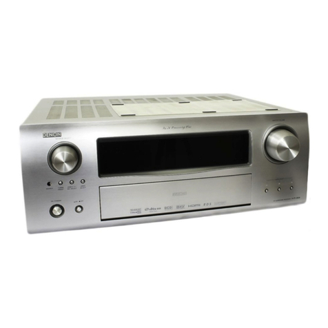
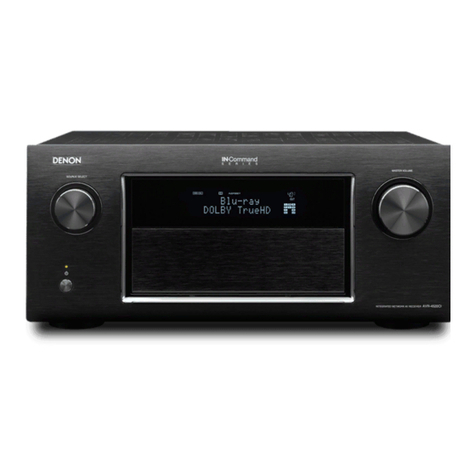
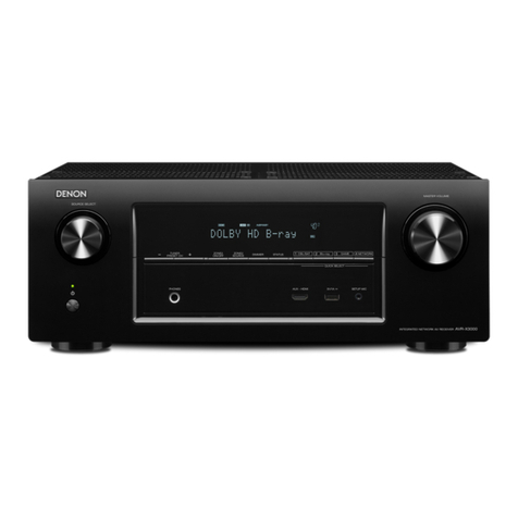
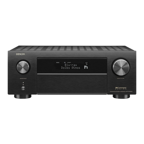
  9. Denon AVRX6500HBKE3 User manual

Denon AVRX6500HBKE3 User manual

This manual suits for next models

7

Other Denon Receiver manuals

Denon AVR-787 User guide

Denon

Denon AVR-787 User guide

Denon AVR-X2200W User manual

Denon

Denon AVR-X2200W User manual

Denon AVR-1909 User manual

Denon

Denon AVR-1909 User manual

Denon AVR-X1000 User manual

Denon

Denon AVR-X1000 User manual

Denon AVR-1882 User manual

Denon

Denon AVR-1882 User manual

Denon AVR-5805 Reference manual

Denon

Denon AVR-5805 Reference manual

Denon AVR-3805 Manual

Denon

Denon AVR-3805 Manual

Denon AVR-888 User manual

Denon

Denon AVR-888 User manual

Denon AVR-689 User manual

Denon

Denon AVR-689 User manual

Denon AVR-4520CI User manual

Denon

Denon AVR-4520CI User manual

Denon AVR-3808CI Administrator guide

Denon

Denon AVR-3808CI Administrator guide

Denon AVR-1911 User manual

Denon

Denon AVR-1911 User manual

Denon AVR-485S User manual

Denon

Denon AVR-485S User manual

Denon AVR-X2400H User manual

Denon

Denon AVR-X2400H User manual

Denon AVR-X3100W User manual

Denon

Denon AVR-X3100W User manual

Denon AVR-2312CI User manual

Denon

Denon AVR-2312CI User manual

Denon AV SURROUND RECEIVER AVR-891 User manual

Denon

Denon AV SURROUND RECEIVER AVR-891 User manual

Denon AVR-1611 User manual

Denon

Denon AVR-1611 User manual

Denon AVR-1707 User manual

Denon

Denon AVR-1707 User manual

Denon AVR-S530BT User manual

Denon

Denon AVR-S530BT User manual

Denon AVR-X2100W User manual

Denon

Denon AVR-X2100W User manual

Denon AVR-1609 User manual

Denon

Denon AVR-1609 User manual

Denon AVR-2808CI User manual

Denon

Denon AVR-2808CI User manual

Denon AVR-X1100W User manual

Denon

Denon AVR-X1100W User manual

Popular Receiver manuals by other brands

Televes ZAS HD SAT user manual

Televes

Televes ZAS HD SAT user manual

Realistic DX-75 Operating and service instructions

Realistic

Realistic DX-75 Operating and service instructions

Saris 4620 Assembly instructions

Saris

Saris 4620 Assembly instructions

Mini DTR 206C PVR user manual

Mini

Mini DTR 206C PVR user manual

RF Elements TwistPort manual

RF Elements

RF Elements TwistPort manual

Yamaha RX-V467 owner's manual

Yamaha

Yamaha RX-V467 owner's manual

Russound SaphIR 858 instruction manual

Russound

Russound SaphIR 858 instruction manual

Quasonix RDMS Firmware update procedure

Quasonix

Quasonix RDMS Firmware update procedure

Pioneer XV-HTD1 Service manual

Pioneer

Pioneer XV-HTD1 Service manual

ATZ HDMI-V2-44HE150 manual

ATZ

ATZ HDMI-V2-44HE150 manual

Sony XNV-770BT MyTomTom Specifications

Sony

Sony XNV-770BT MyTomTom Specifications

Grundig STR 7122 TWIN Service manual

Grundig

Grundig STR 7122 TWIN Service manual

Creative Blaster Modem user guide

Creative

Creative Blaster Modem user guide

Panduit ATLONA AT-OME-RX11 installation guide

Panduit

Panduit ATLONA AT-OME-RX11 installation guide

VOLTCRAFT UTPS-40 operating instructions

VOLTCRAFT

VOLTCRAFT UTPS-40 operating instructions

JVC KW-ADV794 instructions

JVC

JVC KW-ADV794 instructions

Litelink VT-1001 operating instructions

Litelink

Litelink VT-1001 operating instructions

Sangean WR-11 Service manual

Sangean

Sangean WR-11 Service manual

manuals.online logo
manuals.online logoBrands
  • About & Mission
  • Contact us
  • Privacy Policy
  • Terms and Conditions

Copyright 2025 Manuals.Online. All Rights Reserved.

INTEGRATED NETWORK AV RECEIVER
AVR-X6500H
INTEGRATED NETWORK AV AMPLIFIER
AVC-X6500H
Service Manual
Click here!
On-line service parts list
AVR-X6500H: http://dmedia.dmglobal.com/Document/DocumentDetails/24837
AVC-X6500H: http://dmedia.dmglobal.com/Document/DocumentDetails/24838
ONLINE PARTS LIST (P5)
WEB owner’s manual
NA: http://manuals.denon.com/AVRX6500H/NA/EN/index.php
EU: http://manuals.denon.com/AVCX6500H/EU/EN/index.php
AP: http://manuals.denon.com/AVCX6500H/AP/ZH/index.php
JP: http://manuals.denon.com/AVCX6500H/JP/JA/index.php
Upload is planned for the time of a future press release.
BEFORE SERVICING THIS UNIT
ELECTRICAL
MECHANICAL
REPAIR INFORMATION
UPDATING
Ver. 1
Condential
•Forpurposesofimprovement,specicationsanddesignaresubjecttochangewithoutnotice.
• Please use this service manual whenreferringtotheoperatinginstructionswithoutfail.
• Some illustrations usedinthisservicemanualareslightlydifferentfromtheactualproduct.
BEFORE SERVICING THIS UNIT
SAFETY PRECAUTIONS
NOTE FOR SCHEMATIC DIAGRAM
HANDLING THE SEMICONDUCTOR AND OPTICS
ONLINE PARTS LIST
Accessing the Parts List
Searching Part Numbers or Ref. Numbers
NOTE FOR PARTS LIST
SERIAL NUMBER
Serial Number Organization
SKU Code of this Unit
POST-SERVICE PRECAUTIONS
Initializing this Unit
JIG FOR SERVICING
Before Servicing
This Unit Electrical Mechanical Repair Information Updating
2
The following items should be checked for continued protection of the customer and the service technician.
Leakage current check
Before returning the set to the customer, be sure to carry out either (1) a leakage current check or (2) a line to chassis resistance check. If the leakage current exceeds 0.5 milliamps, or if the resistance from chas-
sis to either side of the power cord is less than 460 kohms, the set is defective.
Be sure to test for leakage current with the AC plug in both polarities, in addition, when the set's power is in each state (on, off and standby mode), if applicable.
CAUTION Please heed the following cautions and instructions during servic-
ing and inspection.
◎ Heed the cautions!
Cautions which are delicate in particular for servicing are labeled on the cabinets, the parts and the
chassis, etc. Be sure to heed these cautions and the cautions described in the handling instructions.
◎ Cautions concerning electric shock!
(1) An AC voltage is impressed on this set, so if you touch internal metal parts when the set is energized,
you may get an electric shock. Avoid getting an electric shock, by using an isolating transformer and
wearing gloves when servicing while the set is energized, or by unplugging the power cord when
replacing parts, for example.
(2) There are high voltage parts inside. Handle with extra care when the set is energized.
◎ Caution concerning disassembly and assembly!
Through great care is taken when parts were manufactured from sheet metal, there may be burrs on the
edges of parts. The burrs could cause injury if ngers are moved across them in some rare cases. Wear
gloves to protect your hands.
◎ Use only designated parts!
The set's parts have specic safety properties (re resistance, voltage resistance, etc.). Be sure to use
parts which have the same properties for replacement. The burrs have the same properties. In particular,
for the important safety parts that are indicated by the z mark on schematic diagrams and parts lists,
be sure to use the designated parts.
◎ Be sure to mount parts and arrange the wires as they were originally placed!
For safety seasons, some parts use tapes, tubes or other insulating materials, and some parts are mount-
ed away from the surface of printed circuit boards. Care should also be taken with the positions of the
wires by arranging them and using clamps to keep them away from heating and high voltage parts, so
be sure to set everything back as it was originally placed.
◎ Make a safety check after servicing!
Check that all screws, parts and wires removed or disconnected when servicing have been put back
in their original positions, check that no serviced parts have deteriorated the area around. Then make
an insulation check on the external metal connectors and between the blades of the power plug. And
otherwise check that safety is ensured.
(Insulation check procedure)
Unplug the power cord from the power outlet, disconnect the antenna, plugs, etc., and on the power.
Using a 500V insulation resistance tester, check that the insulation resistance value between the inplug
and the externally exposed metal parts (antenna terminal, headphones terminal, input terminal, etc.) is
1M Ω or greater. If it is less, the set must be inspected and repaired.
Many of the electric and the structural parts used in the set have special safety properties. In most cases
these properties are difcult to distinguish by sight, and the use of replacement parts with higher rat-
ings (rated power and withstand voltage) does not necessarily guarantee that safety performance will
be preserved. Parts with safety properties are indicated as shown below on the wiring diagrams and the
parts list in this service manual. Be sure to replace them with the parts which have the designated part
number.
(1) Schematic diagrams Indicated by the z mark.
(2) Parts lists Indicated by the z mark.
The use of parts other than the designated parts could cause electric shocks, res or other dangerous
situations.
CAUTION Concerning important safety parts
SAFETY PRECAUTIONS
Before Servicing
This Unit Electrical Mechanical Repair Information Updating
3
WARNING:
Parts indicated by the z mark have critical characteristics. Use ONLY replacement parts recommended
by the manufacturer.
CAUTION:
Before returning the set to the customer, be sure to carry out either (1) a leakage current check or (2)
a line to chassis resistance check. If the leakage current exceeds 0.5 milliamps, or if the resistance from
chassis to either side of the power cord is less than 460 kohms, the set is defective.
WARNING:
DO NOT return the set to the customer unless the problem is identied and remedied.
NOTICE:
(1) ALL RESISTANCE VALUES IN OHM. k=1,000 OHM / M=1,000,000 OHM
(2) ALL CAPACITANCE VALUES ARE EXPRESSED IN MICRO FARAD, UNLESS OTHERWISE INDICATED. P
INDICATES MICRO-MICRO FARAD. N INDICATES NANO FARAD.
(3) EACH VOLTAGE AND CURRENT ARE MEASURED AT NO SIGNAL INPUT CONDITION.
(4) CIRCUIT AND PARTS ARE SUBJECT TO CHANGE WITHOUT PRIOR NOTICE.
Electrostatic breakdown of the semi-conductors or optical pickup may occur due to a potential differ-
ence caused by electrostatic charge during unpacking or repair work.
1. Ground for Human Body
Be sure to wear a grounding band (1 M ohm) that is properly grounded to remove any static electricity
that may be charged on the body.
2. Ground for Workbench
Be sure to place a conductive sheet or copper plate with proper grounding (1 M ohm) on the work-
bench or other surface, where the semi-conductors are to be placed. Because the static electricity
charge on clothing will not escape through the body grounding band, be careful to avoid contacting
semi-conductors with your clothing
<Incorrect>
CBA
Grounding Band
Conductive Sheet or
Copper Plate
1MΩ
1MΩ
<Correct>
CBA
NOTE FOR SCHEMATIC DIAGRAM
HANDLING THE SEMICONDUCTOR AND OPTICS
Before Servicing
This Unit Electrical Mechanical Repair Information Updating
4
ONLINE PARTS LIST
Accessing the Parts List
(1) Access from the Service Manual
・ Click the URL link on the cover of the service manual.
Examples of display
NOTE : If the web browser does not open automatically, copy the URL and paste it into the address bar
of the web browser and then press Enter.
(2) Accessing the Part List from the Model Asset Screen.
・ Display Model Asset from New SDI.
・ Click the section displayed as ▼ Link to Part Lists under the model name.
NOTE : If the ▼ Link to Parts List section is not displayed, download the parts table from the Asset list.
Searching Part Numbers or Ref. Numbers
You can search a Parts List for part numbers or Ref. numbers.
(1) Enter the part number or Ref. number in the search window of the Parts List, and press the search
button.
(2) The search results are displayed.
The name of the sheet in which the search part is used and the part’s line are displayed.
(3) Next, click the "Sheet" section of the search results.
1. Parts indicated by "nsp" on this table cannot be supplied.
2. When ordering a part, make a clear distinction between "1" and "I" (i) to avoid mis-supplying.
3. A part ordered without specifying its part number can not be supplied.
4. Part indicated by "@" mark is not illustrated in the exploded and packaging view.
WARNING: Parts indicated by the z mark have critical characteristics. Use ONLY replacement parts
recommended by the manufacturer.
NOTE FOR PARTS LIST
Before Servicing
This Unit Electrical Mechanical Repair Information Updating
5
Product SKU SKU Code
AVRX6500HBKE3 BBY
AVCX6500HBKE2 BBZ
AVCX6500HSPE2 BCA
AVCX6500HBKE1C BCC
AVCX6500HK BCB
SERIAL NUMBER
Serial Number Organization
The 14-digit serial number that contains the code of the manufacturing plant and the manufacturing
date.
SKU
code
14 digits
Factory
code
Cumulative
serial number
Manufactured
Year, month
The last
2digit of year Month
(01 ~ 12)
SKU Code of this Unit
Before Servicing
This Unit Electrical Mechanical Repair Information Updating
6
Make sure to initialize this unit after replacing the microcomputer or any peripheral equipment, or the
digital PCB.
1. Press the power button to turn off the power.
2. While holding down buttons "INFO" and "SETUP" simultaneously, press the power button to turn on
the power.
3. Release the buttons after conrming that the display ashes at 1-second intervals.
* The unit is initialized.
Use network initialization mode to initialize the network related settings.
NOTE: • If the unit fails to enter the service mode in step 3, repeat the procedure from step 1.
• Initializing the device restores the customized settings to the factory settings. Write down
your settings in advance and recongure the settings after initialization.
Use the following jigs (extension cable kit) when repairing the PCBs.
Order with your dealer for the jigs your dealer if necessary.
8U-110084S : EXTENSION UNIT KIT : 1 Set
(See JIG FOR SERVICING)
SETUP
INFO
X
JIG FOR SERVICING
Initializing this Unit
POST-SERVICE PRECAUTIONS
Before Servicing
This Unit Electrical Mechanical Repair Information Updating
7
ELECTRICAL
SCHEMATIC DIAGRAMS
SCH01_DIGITAL CONNECT
SCH02_MAIN CPU
SCH03_EXPANDER
SCH04_AUDIO PLD
SCH05_DIR DA SUPPLY
SCH06_ADI DSP1
SCH07_ADI DSP2
SCH08_ADI DSP3
SCH09_ADI DSP4
SCH10_HDMI SUPPLY
SCH11_DECODER
SCH12_HDMI SW2
SCH13_HDMI SW1
SCH14_IP OSD
SCH15_IP OSD DDR
SCH16_VIDEO PLD
SCH17_HDMI TX
SCH18_E ARC
SCH19_NET MODULE CONNECT
SCH20_AUDIO/VIDEO CONNECT
SCH21_AUDIO VOLUME
SCH22_PREOUT
SCH23_VIDEO SELECTOR
SCH24_CONNECT
SCH25_AMP CONNECT
SCH26_ZONEDAC ADC
SCH27_MAIN DAC
SCH28_FRONT HDMI USB
SCH29_SMPS
SCH30_232C PHONO
SCH31_P.AMP1
SCH32_P.AMP2
SCH33_SPEAKER
SCH34_REG
SCH35_FLD
PRINTED CIRCUIT BOARDS
DIGITAL
AUDIO VIDEO, FRONT HDMI, FRONT USB, CONNECT-1, CONNECT-2, CONNECT-4
DAC, L AMP CONNECT, R AMP CONNECT, FLD,FUNC, CONNECT, TACT, VOL
SPEAKER, HEIGHT2 SP, HP, P.SW, CONNECT-3, P.SW
AMP1, AMP2, SMPS, 232C PHONO
LEVEL DIAGRAM
FRONT ch
CENTER / SURROUND ch
SUBWOOFER ch
SURROUND BACK / HEIGHT1 / HEIGHT2 ch
ZONE2 / ZONE3 ch
BLOCK DIAGRAM
ANALOG AUDIO DIAGRAM
DIGITAL AUDIO DIAGRAM
VIDEO DIAGRAM
POWER DIAGRAM
SEMICONDUCTORS
1. IC's
2. FL DISPLAY
3. Remote Code Table
Before Servicing
This Unit Electrical Mechanical Repair Information Updating
8
SCHEMATIC DIAGRAMS
SCH01_DIGITAL CONNECT All Ref.No. has been described in the parts list are four digits.
But there are less than four digits of printed Ref.No. on the PCB, and they have become four digits after the header by adding "0" in the parts list.
AUDIO SIGNAL
TMDS SIGNAL
ANALOG VIDEO
DIGITAL VIDEO
GND LINE
POWER- LINE
POWER+ LINE
DIGITAL_UNIT
8U-310232(1/19)
BLM21PG221
L6006
BLM21PG221
L6002
BLM21PG221
L6004
BLM21PG221
L6005
BLM21PG221
L6003
R6014
100
2SC4617EB
Q6008
Q6006
KRC402E-RTK
KDS160
D6002
0.1
C6013
R6007
3.3K
R6013
100K
R6006
10K
C6010
OPEN
C6011
OPEN
C6009
OPEN
C6012
1u
R6009
10K
0.1
C6014
KDS160
D6001
R6012
47K
R6010
10K
R6008
OPEN
OPEN
U6002 R6011
4.7K
Q6007
2SA2018
M3.3V
DGND
SWM3.3V
40P-FFC
N6004
33P-SOCKET(C125Z2)
N6012
33P-SOCKET(C125Z2)
N6014
33P-FFC
N6010
33P-FFC
N6011
OPEN
N6002
OPEN
N6003
DV5V
DV3.3V
19P-FFC
N6005
Q6002
KRC402E-RTK
BLM21PG221
L6001
C6002
0.1
Q6003
2SA2018
100K
R6004
C6001
OPEN
Q6005
FDC608PZ
10K
R6003
R6002
3.3K
C6003
0.1
Q6004
KRC402E-RTK
R6001
10K
0
R5075
C6018
OPEN
4.7u
C6020
0.1
C6019
100/6.3
C6016
100/6.3
C6015
C6017
OPEN
4.7u
C6022
OPEN
C6023
0.1
C6021
C9116
330P
BLM21PG221
L9100
R9110
15K
C9122
0.1
C9121
0.01
C9120 1000P
C9101
10/6.3
C9117
10/6.3
R9108
47K
C9118
22/6.3
BLM21PG221
L9104
R9109
0
C9103
1u
SN74AHCU04PWR
U1904
R1929
47
SN74AHCU04PWR
U1904
SN74AHCU04PWR
U1904
R1927
1M
SN74AHCU04PWR
U1904
SN74AHCU04PWR
U1904
1.5K
R1931
SN74AHCU04PWR
U1904
1000P
C1939
SN74AHCU04PWR
U1904
C1936
0.1
C1937
1000P
XCL212B082DR
U9201
SWM5V
DA+5V
VCOM
DA3.3V
DACGND
D5V
DGND
7P-EHs
N6001
OPEN
R9217
OPEN.
C6024
R6005
OPEN
Q6001
HN1K02FU
OPEN
C6004
0
R6015
To_8U-210242-6(N5907)
CONNECT-1_UNIT
To_8U-210242-2(N5001)
DAC_UNIT(1/2)
To_8U-210242-1(N9018)
A.AUDIO/VIDEO_UNIT(1/4)
To_8U-110224-2(N6405)
FLD_UNIT
To_8U-110207-7(N6513)
SMPS_UNIT
To_8U-110224-7(N5204)
CONNECT-3_UNIT
To_8U-110207-8(N3903)
232C/PHONO_UNIT
NET_FACT_RST
Z2DAC_64fs
DLHD
Z2DAC_MUTE
Z2DAC_256fs
Z2DAC_fs
Z2DAC_DATA
MIC_DET
AEXP_DA_6OUT
Z2NETADC_L
DIRECT_LED
MDAX_LED
ILLUMI_LED
H/P_DET
Z2NETADC_R
AVSDA
DAC_CCLK
TU_SCL
TU_INT
SEL_CLK
FANDET_HIGH
MAINADC_RST
AVSCL
ZONESTB
FANDET_ON
AMPSIGDET
232I_MO
DAC_RST1
ZONECLK
THERMALINF
CURRENTDET
DAC_CCS1
ZONEDATA
THERMALINE
SEL_DATA
232O_MI
TU_SDA
DAC_CDATA
TU_SEN
VOL_CLK
TRDET
KEY2
ISELA
FL_DATA
MAIN_RST
KEY1
DOORDET
GREEN_LED
KILLIR
FL_CLK
RED_LED
RCOUT
RC_IN
FL_RST
VSELB
FL_CE1
VOL_DATA
FLASHERIN
POWERKEY
VSELA
FL_CE2
KEY3
ISELB
FL_CTRL
MAIN_BDOWN
DAC1_MCLK
DAC1_-/SW2
DAC2_S/SW1
DAC1_-/SR
DAC1_SW2/SL
DAC2_F/FR
DAC1_S/SW1
DAC2_C/C
DAC1_C/C
DAC1_F/FR
DAC2_-/SR
DAC1_BCK//CK
DAC2_SW2/SL
NETDAC_MCLK
NETDAC_MUTE
NETDAC_BCK
NETDAC_DATA
VOLMUTE
DAC2_LRCK/FL
NETDAC_LRCK
DAC1_LRCK/FL
B501
M3-SIDE
.OPT1
.OPT2
COAX1
COAX2
Z3DAC_fs
Z3DAC_MUTE
Z3DAC_64fs
Z3DAC_256fs
Z3DAC_DATA
MAINADC_256fs
MAINADC_64fs
MAINADC_fs
MAINADC_DATA
Z2DAC_DEMP
Z3DAC_DEMP
MAINPW
CPU_POWER
REMOTE_POWER
DAC_RST2
TU_RST
DAC_CCS2
TRIGGER1
TRIGGER2
DCDET
ASODET
AC_RL1
OPEN
N6006
AEXP_OE_6-9
AEXP_STB_6-9
AEXP_CLK_6-9
0
R9277
0
R9278
0
R9280
0
R9279
0
R9281
0
R9282
0
R9270
0
R9271
0
R9272
0
R9273
0
R9274
0
R9275
0
R9276
DECIN_V
DECIN_CB
DECIN_CR
DECIN_Y
R3951
33
R3940
470
R3950
OPEN
SN74AHCU04PWR
U1905
R3949
OPEN
R3952
33
R3942
OPEN
R3946
47K
SN74AHCU04PWR
U1905
C3943
0.01
R3939
470
R3947
330K
R3941
OPEN
C3942
0.01
SN74AHCU04PWR
U1905
SN74AHCU04PWR
U1905
R3948
330K
R3943
OPEN
SN74AHCU04PWR
U1905
R3944
OPEN
R3945
47K
SN74AHCU04PWR
U1905
SN74AHCU04PWR
U1905 C1956
0.1
C1938
1000P
1
VDD
2
VSS
3
PDN
4
OUT
1
2
3
4
5
6
7
8
9
10
11
12
13
14
15
16
17
18
19
20
21
22
23
24
25
26
27
28
29
30
31
32
33
34
35
36
37
38
39
40
1
2
3
4
5
6
7
8
9
10
11
12
13
14
15
16
17
18
19
20
21
22
23
24
25
26
27
28
29
30
31
32
33
1
2
3
4
5
6
7
8
9
10
11
12
13
14
15
16
17
18
19
20
21
22
23
24
25
26
27
28
29
30
31
32
33
1
2
3
4
5
6
7
8
9
10
11
12
13
14
15
16
17
18
19
20
21
22
23
24
25
26
27
28
29
30
31
32
33
1
2
3
4
5
6
7
8
9
10
11
12
13
14
15
16
17
18
19
20
21
22
23
24
25
26
27
28
29
30
31
32
33
1
2
3
4
5
6
7
8
1
2
3
4
5
6
7
1
2
3
4
5
6
7
8
9
10
11
12
13
14
15
16
17
18
19
1
2
34
5
6
1312
5
6
98
11
10
1
2
3
4
GND
7
VCC
14
2
LX
6
CE
7
AVIN
8
GND
9
PVIN
10
L1
11
L2
1
NC
5
FB
4
NC
3
LX
1
2
3
4
5
6
7
D
6
G
2
S
1
D
3
G
5
S
4
1
2
3
34
56
11 10
9 8
13 12
12
GND
7
VCC
14
MDAX_LED
ILLUMI_LED
DIRECT_LED
DOORDET
FL_CE2
RCOUT
KILLIR
FLASHERIN
FL_CTRL
VAUXV
H/PR
H/PL
VAUXR
VAUXL
H/PR
H/PL
VAUXR
VAUXL
VAUXV
REMOTE_POWER
RC_IN
MIC
MIC
POWERKEY
KEY1
KEY2
KEY3
VSELA
VSELB
ISELA
ISELB
FL_CE1
FL_RST
FL_DATA
H/P_DET
MIC_DET
GREEN_LED
FRONT_IRIN
FRONT_IRIN
RED_LED
B/P_IRIN
B/P_IRIN
ZONEDATA
SEL_DATA
DECIN_V
DECIN_Y
DECIN_CB
DECIN_CR
TRIGGER1
TRIGGER2
232I_MO
CPU_POWER
DLHD
COAX2
COAX1
MAIN_BDOWN
MAIN_RST
FL_CTRL
VSELB
FL_CE2
FL_DATA
RC_IN
POWERKEY
KEY3
ISELA
ISELB
VSELA
KEY1
KEY2
FL_RST
FL_CLK
FL_CE1
GREEN_LED
RED_LED
DOORDET
FLASHERIN
RCOUT
NET_FACT_RST
NET_FACT_RST
CPU_POWER
Z2DAC_64fs
Z2DAC_DATA
DLHD
Z2DAC_MUTE
Z2DAC_fs
Z2DAC_256fs
CPU_POWER
CPU_POWER
Z2NETADC_L
Z2NETADC_R
MIC_DET
DIRECT_LED
MDAX_LED
ILLUMI_LED
H/P_DET
VOL_DATA
Z2DAC_fs
Z3DAC_256fs
Z2DAC_64fs
Z3DAC_fs
Z2DAC_MUTE
Z2DAC_DEMP
Z3DAC_64fs
Z2DAC_DATA
Z3DAC_MUTE
Z3DAC_DEMP
Z2DAC_256fs
Z3DAC_DATA
Z2NETADC_L
Z2NETADC_R
TU_SCL
TU_SDA
TU_SEN
TU_RST
TU_INT
DAC_CCS2
DAC_RST2
DAC_RST1
DAC_CCS1
DAC_CDATA
DAC_CCLK
MAINADC_DATA
MAINADC_fs
MAINADC_64fs
MAINADC_256fs
MAINADC_RST
TRDET
DCDET
FANDET_HIGH
ASODET
FANDET_ON
THERMALINF
AMPSIGDET
THERMALINE
CURRENTDET
232O_MI
AVSCL
AVSDA
AEXP_DA_6OUT
THERMALINE
FANDET_HIGH
THERMALINF
FANDET_ON
TRDET
232I_MO
232O_MI
VOL_DATA
AMPSIGDET
DAC_CCS1
TU_SDA
TU_INT
VOL_CLK
ZONEDATA
MAINADC_RST
TU_SEN
AVSDA
CURRENTDET
DAC_RST1
SEL_DATA
TU_SCL
DAC_CCLK
DAC_CDATA
SEL_CLK
AVSCL
ZONESTB
ZONECLK
KILLIR
.OPT1
.OPT2
COAX2
COAX1
Z3DAC_MUTE
Z3DAC_256fs
Z3DAC_fs
Z3DAC_DATA
Z3DAC_64fs
MAINADC_fs
MAINADC_DATA
MAINADC_256fs
MAINADC_64fs
Z2DAC_DEMP
Z3DAC_DEMP
TU_RST
DAC_CCS2
DAC_RST2
TRIGGER1
TRIGGER2
DCDET
ASODET
AC_RL1
AC_RL1
AEXP_OE_6-9
AEXP_STB_6-9
AEXP_CLK_6-9
AEXP_OE_6-9
AEXP_CLK_6-9
AEXP_STB_6-9
AEXP_DA_6OUT
AEXP_DA_6OUT
AEXP_STB_6-9
AEXP_CLK_6-9
AEXP_OE_6-9
FL_CLK
SEL_CLK
VOL_CLK
ZONECLK
ZONESTB
DECIN_V
DECIN_CB
DECIN_CR
DECIN_Y
.OPT2
.OPT1
D5.2V
TO SMPS
DGND
DGND
D5.2V
FB
TO CPU
SWM
5V
RESET
M3.3V
TO FRONT_FLD
DA3.3V
DAC_RST1
Z2EMP
Z2MUTE
ADCRST
DGND
ADCBCK
Z3DATA
Z2DATA
DGND
DAC_CCLK
Z2BCK
DGND
ADCDATA
DGND
Z2SCK
DAC_RST2
DGND
DAC_CDATA
Z3LRCK
Z3MUTE
Z3BCK
DGND
DGND
Z3EMP
DGND
Z3SCK
ADCLRCLK
ADCSCK
DAC_CCS2
Z2LRCK
DA3.3V
DAC_CCS1
DGND
TRIG12V
M3.3V
DA3.3V
A-7V
A+7V
DGND
DGND
AEXP_STB
AEXP_DATA
AEXP_OE
DGND
AEXP_CLK
FL_CLK
GREENLED
M3.3V
KEY1
ISELB
A-7V
REDLED
KEY3
ISELA
B/PIRIN
MICDET
SWM3.3V
H/PDET
MIC
POWERKEY
H/PGND
PREGND
DGND
A+7V
VSELB
PREGND
H/PL
VSELA
H/PR
DGND
VAUXV
VAUXR
DGND
DGND
FL_CE1
VAUXL
KEY2
SWM5V
FL_DATA
FRONT_IRIN
FL_RST
FLASHERIN_MI
KILLIR_MO
DIRECT_LED
M-DAX_LED
FRONT_IRIN
DOORDET
ILLUMI_LED
D5V
CPUPOWER
DGND
RCIN_MI
M3.3V
FLCE2
RCOUT_MO
FL_CTRL
DGND
DGND
TRIG2
OPT2
DGND
COAX2
232C_Rx
M3.3V
B/P_IRIN
REMOTE3.3V
232C_Tx
TRIG12V
TRIG1
COAX1
DA3.3V
OPT1
TRIGGND
DGND
REMOTE 3.3V
SWM 3.3V
TO SIDE CONNECT
TO DIGITAL IN
TO FRONT CONNECT
3.3V
VS100_IRTX
TO EXPANDER
Z2VCOM
DACGND
TRIGGND
NET FACT RST
CPU_POWER
NC
TO DIR
TO
HDMI SUPPLY
DA SUPPLY
NET MODULE CONNECT
TO APLD
TO 8U-310232(4/19)
TO 8U-310232(5/19) TO 8U-310232(3/19) TO 8U-310232(2/19)TO 8U-310232(4/19)
TO APLD
DIGITAL CONNECT
DGND
DV5V
AEXP_CLK
ZVOLDATA
DECIN_V
VOL_CLK
H/PGND
DECIN_Cr
DGND
VAUXR
AVSCL
VAUXL
ZVOLSTB
ZVOLCLK
DGND
AEXPDATA
AEXP_OE
AVSDA
PREGND
H/PGND
SEL_CLK
H/PL
H/PR
DECIN_Cb
SEL_DATA
MIC
VOL_DATA
AEXP_STB
DECIN_Y
DGND
AUX_V
DGND
DV3.3V
TO DAC UNIT
TO AUDIO/VIDEO UNIT
DA+5V
TUSCL
TUSEN
TUSDA
TURST
TUGPIO
MAINPOWER
AC DET
AMPSIGDET
TEHRMALE
FANDET_ON
FANDET_HIGH
TRDET
CURRENTDET
ASODET
DCDET
THERMALF
NC
TO 8U-310232(11/19)
TO DEC
TO APLD
TO 8U-310232(4/19)
NETDAC_DATA
DGND
DA3.3V
DAC1_F/FR
DGND
DAC1_S/SW1
DGND
DGND
VOLMUTE
NETDAC_BCK
DAC2_LRCK/SBL
NETDAC_MUTE
DAC1_C/C
DGND
DGND
DGND
DLHD
DAC1_LRCK/FL
DGND
DAC1_MCLK
DGND
DAC2_H3/H2L
DAC1_-/SW2
DAC1_SW2/SL
NETDAC_LRCK
NETDAC_MCLK
DAC2_-SB/SBR
DGND
DAC2_H1/H1L
DAC2_H2/H1R
DAC1_-/SR
DAC1_BCK/CK
DAC2_-/H2R
ZADINL....
ZADINR....
AC_RL1
DGND
D5.2V
OPT1
OPT2
CH1: DACF
CH2: DACLRCK
CH3: DACBCK
CH4: DACMCK
3
DAC input
A0
TO 0A
A1
TO 1A
A2
TO 2A
A3
TO 3A
A4
TO 4A
A5
TO 5A
A6
TO 6A
A7
TO 7A
A8
TO 8A
A9
TO 9A
B0
TO 0B
N6012
TO N5907
N6011
TO N5001
N6010
TO N9018
N6001_
TO N6513
N6004_
TO N6405
N6014_
TO N5204
N6005_
TO N3903
Before Servicing
This Unit Electrical Mechanical Repair Information Updating
9
SCH02_MAIN CPU All Ref.No. has been described in the parts list are four digits.
But there are less than four digits of printed Ref.No. on the PCB, and they have become four digits after the header by adding "0" in the parts list.
AUDIO SIGNAL
TMDS SIGNAL
ANALOG VIDEO
DIGITAL VIDEO
GND LINE
POWER- LINE
POWER+ LINE
4.7K
R6256
OPEN
R6269
12MHz
X6201
OPEN
R6267
C6213
10P
R6235
OPEN
DIGITAL_UNIT
8U-310232(2/19)
C6223
OPEN
11P-FFC
N6201
OPEN
U6202
4.7K
R6258
C6212
10P
R5F564MJCDFC
U6201
OPEN
R6264
OPEN
R6263
R6234
680
4.7K
R6229
4.7K
R6262
33
R6237
33
R6241
100
R6232
4.7K
R6226
C6208
0.1
C6204
0.1
C6205
0.1
C6203
0.1
C6202
0.1
C6201
0.1
C6207
0.1
C6210
0.1
C6216
0.1
C6218
0.1
C6219
0.1
C6220
0.1
C6221
0.1
C6222
0.1
C6206
0.1
C6209
0.1
C6214
0.1
C6217
0.1
C6211
0.1
33
R6276
33
R6277
33
R6278
33
R6279
33
R6270
33
R6271
33
R6216
33
R6238
33
R6244
33
R6243
33
R6228
33
R6230
33
R6233
33
R6231
33
R6236
33
R6227
33
R6221
33
R6220
33
R6224
1K
R6225
33
R6222
33
R6223
C6215
0.1
1K
R6207
1K
R6208
1K
R6209
33
R6212
33
R6213
33
R6214
33
R6211
M3.3V
AVSDA
HSDA
HSDA
HSDA
33
R6245
33
R6247
33
R6272
33
R6273
33
R6275
0
R6274
33
R6249
33
R6248
33
R6215
4.7K
R6202
4.7K
R6203
4.7K
R6204
4.7K
R6205
33
R6251
33
R6281
SWM3.3V
IP_MITXO.
IP_MOTXI
IP_RST
IP_SPICS
IP_SPISCK
AVSCL
33
R6289
33
R6290
4.7K
R6295
OPEN
R6299
GUI_WRITE
33
R6257
DGND
M3.3V
0
R6201
DV5V
OPEN
R6288
M3.3V
DGND
DV5V
SWM3.3V
4.7K
R6298
DV3.3V
10K
R6283
-
-
-
33
R6246
33
R6250
33
R6280
33
R6255
SWM5V
SWM5V
R6514
3.3K
R6515
3.9K
R6533
10K
10Kx4
R6287
OPEN
R6219
OPEN
R6314
OPEN
R6300
0
R6218
OPEN
R6210
10Kx4
R6282
OPEN
R6206
OPEN
R6217
OPEN
R6313
33
R6315
4.7K
R6296
33
R9230
33
R6239
150
R6240
33
R6242
33
R6259
33
R6261
10K
R6284
470K
R6285
OPEN
R6286
OPEN
R6511
ARC_INT
AVSCL
ARC_RST
AVSDA
DE_RST
SW1_HINT
H5VDET
SW1_RST
HSCL
SW2_HINT
HSCL
SW2_RST
HSCL
TX_HINT
TX_HAINT
TX_RST
CEC_OUT
CEC_IN
DV3.3V
DSP4_FLAG0
DSP_MISO
DSPI_CLK
DSP_MOSI
DSP4_CS
DSP_RST
DSP4_WRITE
DSP_MISO
DSP3_WRITE
DSP3_FLAG0
DSP_RST
DSP3_CS
DSP_MOSI
DSPI_CLK
DSPI_CLK
DSP_MOSI
DSP2_FLAG3
DSP2_CS
DSP_RST
DSP2_FLAG0
DSP2_WRITE
DSP_MISO
DSP1_FLAG0
DSP1_WRITE
DSPI_CLK
DSP_MISO
DSP_MOSI
DSP1_CS
DSP_RST
MAINDIR_RST
MAINDIR_CE
MAINDIR_CLK
MAINDIR_DIN
MAINDIR_DOUT
AEXP_DA_1IN
MIC_HP_DET
AEXP_CLK_1-5
AEXP_STB_1-5
AEXP_OE_1-5
DC_ASO_PROT
MAIN_BDOWN
MAIN_RST
THERMALINE
FANDET_ON
FANDET_HIGH
THERMALINF
TRDET
232I_MO
232O_MI
MAINADC_RST
DAC_RST1
DAC_CDATA
DAC_CCS1
AMPSIGDET
AVSCL
TU_SCL
CURRENTDET
TU_SEN
TU_SDA
AVSDA
DAC_CCLK
ISELB
DOORDET
ZONESTB
KEY2
FL_CTRL
TU_INT
VSELA
KEY1
RCOUT
FL_RST
VSELB
SEL_CLK
VOL_CLK
POWERKEY
FL_CLK
SEL_DATA
FL_DATA
RC_IN
ZONEDATA
KILLIR
FL_CE1
VOL_DATA
ISELA
FLASHERIN
ZONECLK
GREEN_LED
KEY3
FL_CE2
RED_LED
M3.3V
E_RTS_MOEI
E_CTS_MIEO
E_TxD_MOEI
E_RxD_MIEO
NET_FACT_RST
USB_EN
DSP4_WRITE
DSP3_WRITE
DSP2_WRITE
DSP1_WRITE
NET_FACT_RST
OPEN
R6319
APLD_DATA
Z2PLDAERR
APLD_CS1
.VOLMUTE
MAINPLDERR
Z3PLDAERR
APLD_CLK
AIOS4_STBY_STATUS
AIOS4_WAKEUP
USB_SEL
USB_SEL
DV_POWER2
DV_POWER1
CEC_POWER1
CEC_POWER2
DA_POWER2
DA_POWER1
REMOTE_POWER
CPU_POWER
MAINPW
NET5V_POWER
NET3.3V_POWER
OPEN
R9258
OPEN
R9259
10K
R9260
OPEN
C9633
0
R9262
OPEN
R9263
OPEN
C9634
COMP_DET
OPEN
R6291
4.7K
R6292
10K
R6293
NCU18XH103J60RB
Z6503
10K
R6253
AC_RL1
OPEN
R6294
4.7K
R6252
4.7K
R6254
4.7K
R6260
OPEN
R6265
4.7K
R6266
4.7K
R6268
33
R9264
33
R9265
33
R9266
33
R9267
AEXP_STB_6-9
AEXP_CLK_6-9
AEXP_OE_6-9
33
R9268
33
R9269
1 3
1
2
3
4
5
6
7
8
9
10
11
1
A0
2
A1
3
A2
4
VSS
5
SDA
6
SCL
7
WP
8
VCC
1
AVSS0
2
P05/IRQ13
3
AVCC1
4
P03/IRQ11
5
AVSS1
6
P02/SCK6/IRQ10/AN120
7
P01/RXD6/IRQ9/AN119
8
P00/TXD6/IRQ8/AN118
9
PF5/IRQ4
10
EMLE
11
PJ5
12
VSS
13
PJ3
14
VCL
15
VBATT
16 NC
17
TRST#/PF4
18
MD/FINED
19
XCIN
20
XCOUT
21
RES#
22
XTAL/P37
23
VSS
24
EXTAL/P36
25
VCC
26
UPSEL/P35(IN)/NMI
27
P34/SCK6/SCK0/IRQ4
28
P33/TIOCD0/RXD6/RXD0/IRQ3-DS
29
P32/TIOCC0/TXD6/TXD0/IRQ2-DS
30
TMS/PF3
31
TDI/PF2/RXD1
32
P31/IRQ1-DS
33
P30/RXD1
34
TCK/FINEC/PF1/SCK1
35
TD0/TXD1/PF0
36
P27/SCK1
37
P26/TXD1
38
P25/RXD3
39
VCC
40
P24/SCK3
41
VSS
42
P23/TXD3
43
P22/SCK0
44
P21/RXD0/IRQ9
45
P20/TXD0/IRQ8
46
P17/SCK1/TXD3/IRQ7
47
P87/TXD10/TIOCA2
48
P16/TXD1/RXD3/IRQ6
49
P86/RXD10
50
P15/RXD1/SCK3/IRQ5
51
P14/IRQ4
52
P13/TXD2/IRQ3
53
P12/RXD2/IRQ2
54
VCC_USB
55
USB0_DM
56
USB0_DP
57
VSS_USB
58
AVCC_USBA
59
USBA_PREF
60
AVSS_USBA
61
PVSS_USBA
62
VSS2_USBA
63
USBA_DM
64
USBA_DP
65
VSS1_USBA
66
VCC_USBA
67
P11/SCK2/IRQ1
68
P10/IRQ0
69
P53
70
P52/RXD2
71
P51/SCK2
72
P50/TXD2
73
VSS
74
P83/SCK10
75
VCC
76
UB/PC7/TXD8/IRQ14
77
PC6/RXD8/IRQ13
78
PC5/SCK8
79
P82/TXD10
80
P81/RXD10
81
P80/SCK10
82
PC4/SCK5
83
PC3/TXD5
84
P77/TXD11
85
P76/RXD11
86
PC2/RXD5
87
P75/SCK11
88
P74
89
PC1/SCK5/IRQ12
90
VCC
91
PC0/IRQ14
92
VSS
93
P73
94
PB7/TXD9
95
PB6/RXD9
96
PB5/SCK9
97
PB4
98
PB3/SCK4/SCK6
99
PB2
100
PB1/TXD4/TXD6/IRQ4-DS
101
P72
102
P71
103
VCC
104
PB0/RXD4/RXD6/IRQ12
105
VSS
106
PA7
107
PA6
108
PA5
109
PA4/TXD5/SSDA5/IRQ5-DS
110
PA3/RXD5/SSCL5
111
TRDATA3/PG7
112
PA2/RXD5
113
TRDATA2/PG6
114
PA1/SCK5/IRQ11
115
VCC
116
TRCLK/PG5
117
VSS
118
PA0
119
TRSYNC/PG4
120
P67/IRQ15
121
TRDATA1/PG3
122
P66
123
TRDATA0/PG2
124
P65
125
PE7/IRQ7/AN105
126
PE6/IRQ6/AN104
127
VCC
128
P70
129
VSS
130
PE5/IRQ5/AN103
131
PE4/AN102
132
PE3/AN101
133
PE2/RXD12/IRQ7-DS/AN100
134
PE1/TXD12
135
PE0/SCK12
136 P64
137 P63
138 P62
139 P61
140 VSS
141 P60
142 VCC
143
PD7/IRQ7/AN107
144 PG1
145
PD6/IRQ6/AN106
146 PG0
147
PD5/IRQ5/AN113
148
PD4/IRQ4/AN112
149 P97
150
PD3/IRQ3/AN111
151 VSS
152 P96
153 VCC
154
PD2/IRQ2/AN110
155 P95
156
PD1/IRQ1/AN109
157 P94
158
PD0/IRQ0/AN108
159
P93/AN117
160
P92/RXD7/AN116
161
P91/AN115
162 VSS
163
P90/TXD7/AN114
164 VCC
165
P47/IRQ15-DS/AN007
166
P46/IRQ14-DS/AN006
167
P45/IRQ13-DS/AN005
168
P44/IRQ12-DS/AN004
169
P43/IRQ11-DS/AN003
170
P42/IRQ10-DS/AN002
171
P41/IRQ9-DS/AN001
172
VREFL0
173 P40
174
VREFH0
175
AVCC0
176
P07/IRQ15
12
34
56
78
12
34
56
78
12
34
56
78
12
34
56
78
POWERKEY
AEXP_OE
AEXP_STB
THERMALINE
TRDET
MIC_HP_DET
DC_ASO_PROT
AEXP_DA_1IN
AEXP_CLK
CURRENTDET
FLASHERIN
232O_MI
TU_SEN
TU_SCL
232I_MO
TU_SDA
MAINPW
AMPSIGDET
AVSCL
AVSDA
VOL_DATA
ZONECLK
ZONEDATA
VOL_CLK
ZONESTB
RCOUT
RC_IN
ISELB
MAIN_RST
ISELA
FL_CE1
FL_CLK
FL_CTRL
FL_CE2
VSELA
CPU_POWER
FANDET_ON/HIGH
FL_DATA
FL_RST
MAIN_BDOWN
KEY3
KEY2
KEY1
DA_POWER1
MAINDIR_DIN
MAINADC_RST
MAINDIR_CLK
MAINDIR_DOUT
MAINDIR_RST
MAINDIR_CE
Z3PLDAERR
MAINPLDERR
Z2PLDAERR
APLD/DAC_CLK
APLD/DAC_DATA
DAC_RST1
DAC_CCS1
DSP_MISO
DSP1_CS
DSP_RST
DSP2_CS
DSP4_FLAG0
DSP2_FLAG3
DSP1_FLAG0
DSP3_FLAG0
DSP3_CS
DSP2_FLAG0
HSCL
HSDA
HSDA
HSCL
IP_MOTXI
IP_MITXO.
IP_SPICS
CEC_IN
CEC_OUT
CEC_OUT
CEC_IN
TX_RST
HSDA
HSCL
IP_RST
IP_SPISCK
IP_SPICS
H5VDET
DE_RST
DSP4_CS
DV_POWER2
DV_POWER1
CEC_POWER1
SW1_RST
SW2_RST
IP_RST
TX_RST
E_RxD_MIEO
NET3.3V_POWER
NET_FACT_RST
E_TxD_MOEI
RED_LED
GREEN_LED
IP_SPISCK
IP_MOTXI
IP_MITXO.
DSP_MOSI
DSPI_CLK
DE_RST
DOORDET
E_CTS_MIEO
VSELB
AIOS4_STBY_STATUS
AIOS4_WAKEUP
GUI_WRITE
GUI_WRITE
SEL_CLK
MIC_HP_DET
DC_ASO_PROT
232O_MI
232I_MO
DSP_MOSI
DSPI_CLK
DSP_RST
DSP_MISO
DSP3_WRITE
DSPI_CLK
DSP4_WRITE
DSP2_WRITE
DSPI_CLK
DSP_MISO
DSP_MOSI
DSP_RST
DSP1_WRITE
DSP_RST
DSP_RST
DSP_MOSI
DSP_MISO
MAINPW
REMOTE_POWER
CPU_POWER
FL_CE2
KEY2
KEY1
FL_CE1
KEY3
RCOUT
FLASHERIN
MAIN_BDOWN
VSELA
MAIN_RST
POWERKEY
FL_CLK
ISELB
FL_RST
VSELB
RC_IN
ISELA
FL_DATA
RED_LED
FL_CTRL
GREEN_LED
DOORDET
TU_SDA
SEL_CLK
DAC_RST1
AVSCL
ZONECLK
AVSDA
ZONEDATA
VOL_CLK
SEL_DATA
ZONESTB
AMPSIGDET
TU_SCL
TU_SEN
TU_INT
CURRENTDET
MAINADC_RST
NET5V_POWER
THERMALINE
THERMALINF
FANDET_ON
FANDET_HIGH
TRDET
KILLIR
E_RTS_MOEI
SEL_DATA
ARC_INT
USB_EN
REMOTE_POWER
SW2_RST
SW1_HINT
SW1_RST
H5VDET
DSP1_WRITE
E_RxD_MIEO
E_TxD_MOEI
E_CTS_MIEO
NET_FACT_RST
E_RTS_MOEI
NET5V_POWER
NET3.3V_POWER
DSP3_WRITE
DSP2_WRITE
DSP4_WRITE
USB_EN
MAINDIR_RST
NET_FACT_RST
DAC_CCS1
DAC_CDATA
DAC_CCLK
MAINDIR_CE
MAINDIR_CLK
MAINDIR_DIN
MAINDIR_DOUT
DSP1_CS
DSP_MOSI
DSP_MISO
DSPI_CLK
DSP2_FLAG3
DSP2_FLAG0
DSP2_CS
DSP3_FLAG0
DSP3_CS
DSP4_FLAG0
DSP4_CS
DV_POWER1
DV_POWER2
CEC_POWER2
TX_HAINT
TX_HINT
SW2_HINT
DSP1_FLAG0
CEC_POWER2
AVSCL
AVSDA
HSCL
HSDA
TX_HAINT
SW1_HINT
SW2_HINT
TX_HINT
CEC_POWER1
VOL_DATA
FANDET_ON
FANDET_HIGH
FANDET_ON/HIGH
.VOLMUTE
APLD_CLK
DAC_CCLK
APLD_DATA
DAC_CDATA
APLD/DAC_CLK
APLD_CS1
APLD/DAC_DATA
KILLIR
ARC_RST
ARC_INT
AVSCL
AVSDA
DA_POWER1
DSP_RST
APLD_DATA
MAINPLDERR
.VOLMUTE
Z2PLDAERR
Z3PLDAERR
APLD_CS1
APLD_CLK
AIOS4_STBY_STATUS
AIOS4_WAKEUP
USB_SEL
ARC_RST
UNIT_TEMP
COMP_DET
THERMALINF
COMP_DET
TU_INT
UNIT_TEMP
AC_RL1
AC_RL1
USB_SEL
AEXP_STB
AEXP_DA_1IN
AEXP_CLK
AEXP_OE
EMLE
TDO
MD
TRST
MAIN CPU
VCC
UB
GND
RESET
TCK
TMS
TDI
TO EXPANDER
TO DIGITAL CONNECT
TO 8U-310232(10/19)
TO
HDMI SUPPLY
TO 8U-310232(11/19)
TO
DECODER
TO 8U-310232(13/19)
TO
HDMI SW1
TO 8U-310232(12/19)
TO
HDMI SW2
TO 8U-310232(14/19)TO 8U-310232(17/19)
TO
HDMI TX
TO
NETWORK MODULE
CONNECT
TO
IP/OSD
TO DSP3 TO DSP1TO DSP2TO DSP4
89:
42:
43:
44:
2:
6:
TO 8U-310232(9/19) TO 8U-310232(8/19) TO 8U-310232(7/19) TO 8U-310232(6/19) TO 8U-310232(3/19) TO 8U-310232(1/19)
TO 8U-310232(19/19)
TO DIR/
DA POWER
TO 8U-310232(5/19)
OPEN
O
O
OPEN
OPEN
OPEN
E2
OPEN
R6314
OPEN
OPEN
E3
R6218
OPENOPEN
R6300
OPEN
O
JP
OPEN
OPEN
OPEN
OPEN
OPEN
R6313
R6217
OPEN
OPEN
OPEN
E1C
OPEN
OPEN
R6219
OPEN
(USA)
(EUROPE)
(CHINA) (JAPAN)
135:
134:
133:
TO eARC
TO 8U-310232(18/19)
AUDIO PLD
TO 8U-310232(4/19)
8A
TO A8
B1
TO 1B
B2
TO 2B
B3
TO 3B
B4
TO 4B
B5
TO 5B
B6
TO 6B
B7
TO 7B
B8
TO 8B
B9
TO 9B
C0
TO 0C
C1
TO 1C
C2
TO 2C
C3
TO 3C
C4
TO 4C
C5
TO 5C
Before Servicing
This Unit Electrical Mechanical Repair Information Updating
10