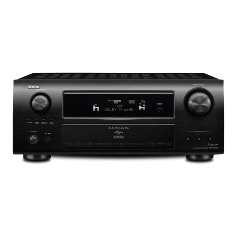
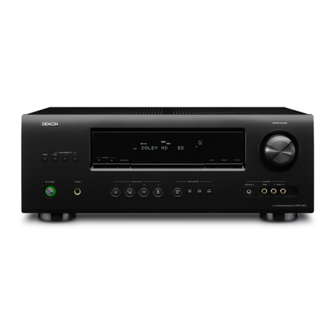
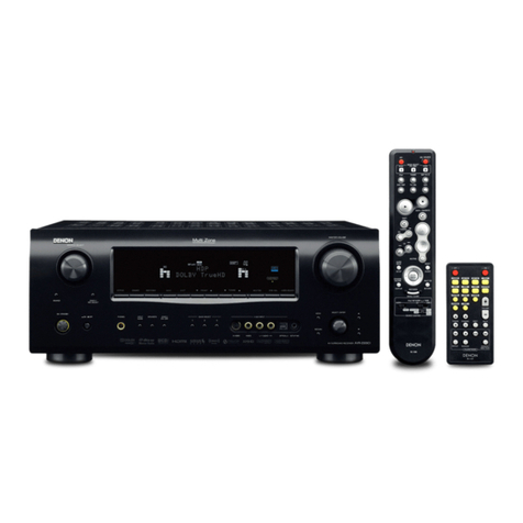
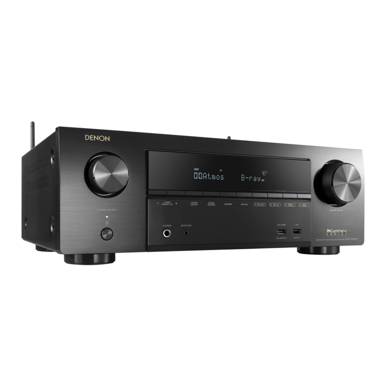
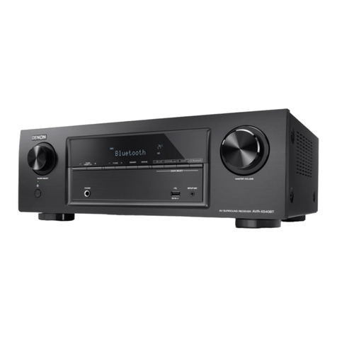
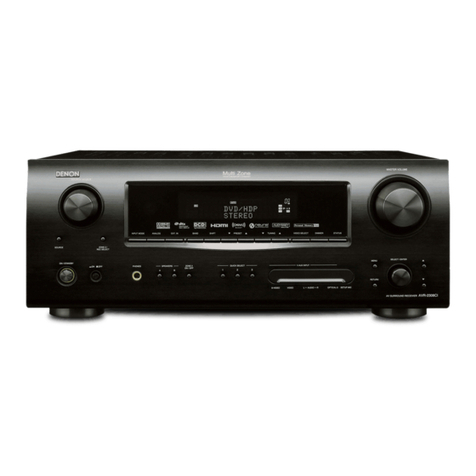
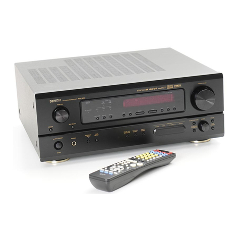
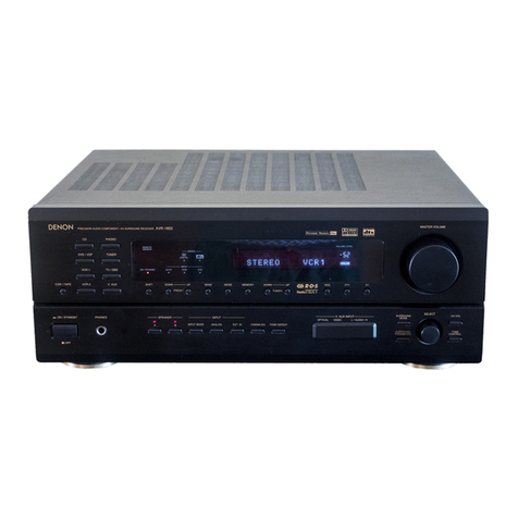
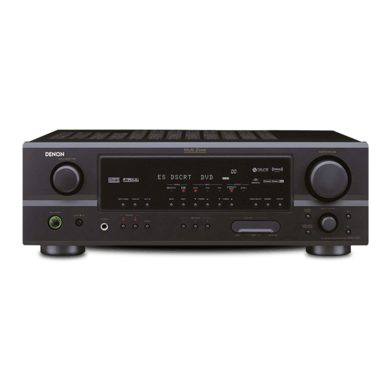
Denon AVR-E200 User manual

START::|qzT7t3cIXfGvpSN6RPbAWw==|CqN5zsKr96YP4BreAbdr2NqZwvosEWSgtpmHebiaRr4=|RtRIz5LbaS+BXuKmvA5tJg==|::END
D&M Holdings Inc.
SERVICE MANUAL
e
e
Ver. 1
S0573-0V01DM/DG1302
• Some illustrations using in this service manual are slightly different from the actual set.
• Please use this service manual with referring to the operating instructions without fail.
• For purposes of improvement, specications and design are subject to change without notice.
MODEL JP E3 E2 E1 EA E1C E1K E3B
AVR-E200
P P
AVR-X500
P P P
AV SURROUND RECEIVER

2
CONTENTS
ABOUT THIS MANUAL.............................................................3
What you can do with this manual ............................................3
Using Adobe Reader (Windows version) ..................................4
SAFETY PRECAUTIONS..........................................................6
NOTE FOR SCHEMATIC DIAGRAM.........................................7
NOTE FOR PARTS LIST...........................................................7
TECHNICAL SPECIFICATIONS................................................8
DIMENSION...............................................................................8
CAUTION IN SERVICING..........................................................9
Initializing AV SURROUND RECEIVER....................................9
Service Jig ................................................................................9
DISASSEMBLY........................................................................10
1. FRONT PANEL ASSY ........................................................12
2. DIGITAL PCB ASSY...........................................................13
3. RADIATOR ASSY...............................................................14
4. STANDBY PCB ..................................................................15
5. REGULATOR PCB.............................................................15
6. TRANS POWER ................................................................15
SPECIAL MODE......................................................................16
Special mode setting button....................................................16
1. µcom/DSP/OSD Version display mode..............................17
2. Errors checking mode (Displaying the protection history)..18
WHEN THE MICROPROCESSOR IS REPLACED WITH A NEW
ONE..........................................................................................20
PROCEDURE FOR UPGRADING THE VERSION OF THE
FIRMWARE..............................................................................20
1. Preparations.......................................................................20
2. UPDATE FIRMWARE ........................................................25
3. Notice:................................................................................44
Conrming the rmware’s number after upgraded..................44
ADJUSTMENT.........................................................................45
Surround modes and surround parameters........................46
TROUBLE SHOOTING............................................................48
1. POWER..............................................................................48
2. Analog video ......................................................................49
3. HDMI/DVI...........................................................................50
4. AUDIO................................................................................55
CLOCK FLOW & WAVE FORM IN DIGITAL BLOCK.............58
ANALOG AUDIO/VIDEO BLOCK DIAGRAM .........................59
POWER BLOCK DIAGRAM....................................................60
LEVEL DIAGRAM....................................................................61
WIRING DIAGRAM..................................................................65
PRINTED WIRING BOARDS...................................................66
FRONT....................................................................................66
DIGITAL...................................................................................69
F-HDMI....................................................................................71
POWER...................................................................................71
REGULATOR ..........................................................................73
TUNER....................................................................................75
POWER KNOB .......................................................................75
PORTABLE .............................................................................75
HEADPHONE .........................................................................75
USB.........................................................................................75
FOR HDMI FFC CABLE..........................................................75
SCHEMATIC DIAGRAMS........................................................76
SCHEMATIC DIAGRAMS (1/9)...............................................76
FRONT PART..........................................................................76
SCHEMATIC DIAGRAMS (2/9)...............................................77
POWER PART ........................................................................77
SCHEMATIC DIAGRAMS (3/9)...............................................78
MAIN PART.............................................................................78
SCHEMATIC DIAGRAMS (4/9)...............................................79
INPUT & VOLUME PART........................................................79
SCHEMATIC DIAGRAMS (5/9)...............................................80
VIDEO PART...........................................................................80
SCHEMATIC DIAGRAMS (6/9)...............................................81
DSP PART...............................................................................81
SCHEMATIC DIAGRAMS (7/9)...............................................82
MCU PART..............................................................................82
SCHEMATIC DIAGRAMS (8/9)...............................................83
HDMI PART.............................................................................83
SCHEMATIC DIAGRAMS (9/9)...............................................84
FRONT-HDMI IN PART...........................................................84
EXPLODED VIEW....................................................................85
PACKING VIEW.......................................................................87
SEMICONDUCTORS...............................................................88
1. IC's.....................................................................................88
2. FL DISPLAY .....................................................................107

3
ABOUT THIS MANUAL
Read the following information before using the service manual.
What you can do with this manual
Jump to the target of a schematic diagram
connector
Click the Ref. No. of the target connector in the red box
around a schematic diagram connector.
• Thescreenjumpstothetargetconnector.
• Pagemagnificationstaysthesameasbeforethe
jump.
Search for a Ref. No. (phrase)
(Ctrl+Shift+F)
You can use the search function in Acrobat Reader to
searchforaRef.No.inschematicdiagrams,printed
wiringboarddiagrams,blockdiagrams,andpartslists.
1.PressCtrl+Shift+Fonthekeyboard.
• TheSearchwindowappears.
Ctrl
Shift
F
2.EntertheRef.No.youwanttosearchforinthe
Searchwindow,andthenclicktheSearch button.
• Alistofsearchresultsappears.
3.Click an item on the list.
•Thescreenjumpstothepageforthatitem,and
thesearchphraseisdisplayed.

4
Using Adobe Reader (Windows version)
• Properties
Clickthisbuttonandcheckthattheprinterissettoa
suitablepapersize.
• Pagetoprint
Selectthefollowingcheckbox.
"More Options" : "Current View"
• PageSizing&Handling
Selectthefollowingcheckbox.
"Size" / "SizeOptions" : "Fit"
Add notes to this data (Sign)
TheSignfunctionletsyouaddnotestothedatainthis
manual.
Savetheleonceyouhavenishedaddingnotes.
[Example using Adobe Reader X]
On the "View" menu, click "Sign".
• TheSignpaneappears.
[Example using Adobe Reader 9]
On the "Document" menu, click "Sign".
Magnify schematic / printed wiring board
diagrams - 1
(Ctrl+Space, mouse operation)
PressCtrl+Spaceon thekeyboardanddragthe
mousetoselecttheareayouwanttoview.
• Theselectedareaismagnied.
Ctrl Space
0
• Whenyouwanttomovetheareashown,holddown
Space and drag the mouse.
• Whenyouwant toshowafullpage view,press
Ctrl+0onthekeyboard.
Printamagniedpartofthemanual
ThePropertiesdialogboxandfunctionswillvarydependingonyourprinter.
1.Dragthemousetomagnifythepartyouwanttoprint.
2.On the "File" menu, click "Print".
3.CongurethefollowingsettingsinthePrintdialogbox.
4.Click the Printbuttontostartprinting.

5
Magnify schematic / printed wiring board
diagrams - 2
(Pan&Zoomfunction)
ThePan&Zoomfunctionletsyou seewhichpartofa
magnieddiagramisbeingshowninaseparatewindow.
[Example using Adobe Reader X]
On the "View"menu,pointto"Zoom", and then click
"Pan&Zoom".
• ThePan&Zoomwindowappearsonthescreen.
[Example using Adobe Reader 9]
On the "Tools"menu,pointto"Select&Zoom", and
then click "Pan&ZoomWindow".
Magnify schematic / printed wiring board
diagrams - 3
(Loupe Tool function)
TheLoupeToolfunctionletsyoumagnifyaspecific
partofadiagraminaseparatewindow.
[Example using Adobe Reader X]
On the "View"menu,pointto"Zoom", and then click
"Loupe Tool".
• TheLoupeToolwindowappearsonthescreen.
[Example using Adobe Reader 9]
On the "Tools"menu,pointto"Select&Zoom", and
then click "Loupe Tool Window".

6
SAFETYPRECAUTIONS
Thefollowingitemsshouldbecheckedforcontinuedprotectionofthecustomerandtheservicetechnician.
LEAKAGE CURRENT CHECK
Beforereturningthesettothecustomer,besuretocarryouteither(1)aleakagecurrentcheckor(2)alinetochassis
resistancecheck.Iftheleakagecurrentexceeds0.5milliamps,oriftheresistancefromchassistoeithersideofthe
powercordislessthan460kohms,thesetisdefective.
BesuretotestforleakagecurrentwiththeACpluginbothpolarities,inaddition,whentheset'spowerisineachstate(on,
offandstandbymode),ifapplicable.
CAUTION Pleaseheedthefollowingcautionsandinstructionsduringservicingand
inspection.
◎Heed the cautions!
Cautionswhicharedelicateinparticularforservicing
arelabeledonthecabinets,thepartsandthechassis,
etc. Be sure to heed these cautions and the cautions
described in the handling instructions.
◎Cautions concerning electric shock!
(1) AnACvoltageisimpressedonthisset,soif
youtouchinternalmetalpartswhenthesetis
energized,youmaygetanelectricshock.Avoid
gettinganelectricshock,byusinganisolating
transformer and wearing gloves when servicing
whilethesetisenergized,orbyunpluggingthe
powercordwhenreplacingparts,forexample.
(2) Therearehighvoltagepartsinside.Handlewith
extra care whenthesetisenergized.
◎Caution concerning disassembly and
assembly!
Throughgreatcareistakenwhenpartswere
manufacturedfromsheetmetal,theremaybeburrs
ontheedgesofparts.Theburrscouldcauseinjuryif
ngersaremovedacrosstheminsomerarecases.
Wearglovestoprotectyourhands.
◎Use only designated parts!
Theset'spartshavespecicsafetyproperties(re
resistance,voltageresistance,etc.).Besuretouse
partswhichhavethesamepropertiesforreplacement.
Theburrshavethesameproperties.Inparticular,for
theimportantsafetypartsthatareindicatedbythez
markonschematicdiagramsandpartslists,besureto
use the designatedparts.
◎Be sure to mount parts and arrange the wires
as they were originally placed!
Forsafetyseasons,somepartsusetapes,tubesor
otherinsulatingmaterials,andsomepartsaremounted
awayfromthesurfaceofprintedcircuitboards.
Careisalsotakenwiththepositionsofthewiresby
arrangingthemandusingclampstokeepthemaway
fromheatingandhighvoltageparts,sobesuretoset
everythingbackasitwasoriginallyplaced.
◎Make a safety check after servicing!
Checkthatallscrews,partsandwiresremovedor
disconnectedwhenservicinghavebeenputbackin
theiroriginalpositions,checkthatnoservicedparts
havedeterioratetheareaaround.Thenmakean
insulation check on the external metal connectors and
betweenthebladesofthepowerplug,andotherwise
checkthatsafetyisensured.
(Insulationcheckprocedure)
Unplugthepowercordfromthepoweroutlet,
disconnecttheantenna,plugs,etc.,andonthepower.
Using a 500V insulation resistance tester, check that
theinsulationresistancevaluebetweentheinplugand
theexternallyexposedmetalparts(antennaterminal,
headphonesterminal,inputterminal,etc.)is1MΩor
greater.Ifitisless,thesetmustbeinspectedand
repaired.
Manyoftheelectricandthestructuralpartsusedin
thesethavespecialsafetyproperties.Inmostcases
thesepropertiesaredifculttodistinguishbysight,and
theuseofreplacementpartswithhigherratings(rated
powerandwithstandvoltage)doesnotnecessarily
guaranteethatsafetyperformancewillbepreserved.
Partswithsafetypropertiesareindicatedasshown
belowonthewiringdiagramsandthepartslistinthis
servicemanual.Besuretoreplacethemwiththeparts
whichhavethedesignatedpartnumber.
(1) Schematicdiagrams.......Indicatedbythez mark.
(2) Partslists.......Indicatedbythezmark.
Theuseofpartsotherthanthe
designatedpartscouldcauseelectric
shocks,resorotherdangerous
situations.
CAUTION Concerning important safety
parts
7
NOTE FOR SCHEMATIC DIAGRAM
WARNING:
Partsindicatedbythezmarkhavecriticalcharacteristics.UseONLYreplacementpartsrecommendedbythemanufacturer.
CAUTION:
Beforereturningthesettothecustomer,besuretocarryouteither(1)aleakagecurrentcheckor(2)alinetochassisresistancecheck.If
theleakagecurrentexceeds0.5milliamps,oriftheresistancefromchassistoeithersideofthepowercordislessthan460kohms,theset
is defective.
WARNING:
DONOTreturnthesettothecustomerunlesstheproblemisidentiedandremedied.
NOTICE:
ALLRESISTANCEVALUESINOHM.k=1,000OHM/M=1,000,000OHM
ALLCAPACITANCEVALUESAREEXPRESSEDINMICROFARAD,UNLESSOTHERWISEINDICATED.PINDICATESMICRO-MICRO
FARAD.EACHVOLTAGEANDCURRENTAREMEASUREDATNOSIGNALINPUTCONDITION.CIRCUITANDPARTSARESUBJECT
TOCHANGEWITHOUTPRIORNOTICE.
NOTE FOR PARTS LIST
Parts indicated by "nsp" on this table cannot be supplied.
When ordering a part, make a clear distinction between "1" and "I" (i) to avoid mis-supplying.
A part ordered without specifying its part number can not be supplied.
General-purpose Carbon Chip Resistors are not included are not included in the P.W.Board parts list.
(Refer to the Schematic Diagram for those parts.)
Parts indicated by the zmark have critical characteristics. Use ONLY replacement parts recommended by the manufacturer.
General-purpose Carbon Film Resistor in the P.W.Board parts list. (Refer to the Schematic Diagram for those parts.)
Part indicated by "★" mark is not illustrated in the exploded view.
WARNING:
1.
2.
3.
4.
5.
6.
●Resistors
RD: Carbon
RC: Composition
RS : Metal oxide film
RW: winding
RN: Metal film
RK : Metal mixture
P : Pulse-resistant type
NL : Low noise type
NB : Non-burning type
FR : Fuse-resistor
F : Lead wire forming
2B : 1/8 W
2E : 1/4 W
2H : 1/2 W
3A : 1 W
3D : 2 W
3F : 3 W
3H : 5 W
F : ±1%
G:±2%
J : ±5%
K : ±10%
M : ±20%
Ex.: RN
Type 14K
Shape
and per-
formance
2E
Power 182
Resist-
ance
G
Allowable
error
FR
Others
*Resistance 1800ohm=1.8kohm1 8 2 Indicates number of zeros after effective number.
2-digit effective number.
1.2ohm1 R 2
2-digit effective number, decimal point indicated by R.
1-digit effective number.
: Units: ohm
●Capacitors
CE : Aluminum foil
electrolytic
CA : Aluminium solid
electrolytic
CS : Tantalum electrolytic
CQ: Film
CK : Ceramic
CC: Ceramic
CP : Oil
CM: Mica
CF : Metallized
CH: Metallized
HS : High stability type
BP : Non-polar type
HR: Ripple-resistant type
DL : For change and discharge
HF : For assuring high frequency
U : UL part
C : CSA part
W : UL-CSA part
F : Lead wire forming
0J : 6.3 V
1A : 10 V
1C : 16 V
1E : 25 V
1V : 35 V
1H : 50 V
2A : 100 V
2B : 125 V
2C : 160 V
2D : 200 V
2E : 250 V
2H : 500 V
2J : 630 V
F : ±1%
G:±2%
J : ±5%
K : ±10%
M : ±20%
Z : ±80%
: - 20%
P : +100%
C : ±0.25pF
D : ±0.5pF
= : Others
Ex.: CE
Type 04W
Shape
and per-
formance
1H
Dielectric
strength
3R2
Capacity M
Allowable
error
BP
Others
・Units:μF.
2200μF2 2 2 Indicates number of zeros after effective number.
2-digit effective number. ・Units:μF.
2.2μF2 R 2
2-digit effective number, decimal point indicated by R
1-digit effective number.
*Capacity (electrolyte only)
・When the dielectric strength is indicated in AC,"AC" is included after the dielectric strength value.
*Capacity (except electrolyte)
・Units:pF
2200pF=0.0022μF2 2 2
Indicates number of zeros after effective number. (More than 2)
2-digit effective number. ・Units:pF
220pF2 2 1
2-digit effective number.
Indicates number of zeros after effective number. (0 or 1)
NOTEFORPARTSLIST

8
TECHNICALSPECIFICATIONS
nAudio Section
• Poweramplier
Rated output :
Front :
75W+75W(8Ω,20Hz–20kHzwith0.08%T.H.D.)
110W+110W(6Ω,1kHzwith0.7%T.H.D.)
130W+130W(6Ω, JEITA)
Center :
75W(8Ω,20Hz–20kHzwith0.08%T.H.D.)
110W(6Ω,1kHzwith0.7%T.H.D.)
130W(6Ω,JEITA)
Surround:
75W+75W(8Ω,20Hz–20kHzwith0.08%T.H.D.)
110W+110W(6Ω,1kHzwith0.7%T.H.D.)
130W+130W(6Ω,JEITA)
Output connectors :6–16Ω
• Analog
Input sensitivity/Input impedance : 200mV/47kΩ
Frequency response:10Hz–100kHz—+1,–3dB(DIRECTmode)
S/N :98dB(IHF–Aweighted,DIRECTmode)
nVideo section
• Standard video connectors
Input/output level and impedance : 1Vp-p,75Ω
Frequency response:5Hz–10MHz—0,–3dB
nTuner section
[FM](Note:μVat75Ω,0dBf=1x10–15W)
Receiving Range (forE3/E3B):
[FM]87.5MHz–107.9MHz [AM]520kHz–1710kHz
Receiving Range (forE2,E1C):
[FM]87.5MHz–108.0MHz [AM]522kHz–1611kHz
Usable Sensitivity :
[FM]1.2μV(12.8dBf) [AM]18μV
50 dB Quieting Sensitivity :
[FM]MONO2.8μV(20.2dBf)
S/N (IHF-A) :
[FM]MONO70dB(IHF–Aweighted,DIRECTmode)
STEREO67dB(IHF–Aweighted,DIRECTmode)
TotalharmonicDistortion(at1kHz):
[FM]MONO0.7%
STEREO1.0%
nGeneral
Powersupply:(forE3/E3B): AC120V,60Hz
(forE2/E1) : AC230V,50Hz/60Hz
(forE1C) : AC220V,50Hz
Powerconsumption:330W
0.3W(Standby)
DIMENSION
15/32
(12.0)
11 23/64 (288.5)
12 9/16 (319.0)
1 27/32
(47.0)
7 51/64 (198.0)
1 23/32
(43.5)
47/64
(18.5)
17 3/32 (434.0)
5 23/64 (136.0)
5 15/16 (151.0)
2 23/64
(60.0)
1 49/64
(45.0)
19/32 (15.0)
13 35/64 (344.0)
1 49/64
(45.0)
Unit : in. (mm)
Weight : 17 lbs 7 oz (7.9 kg)

9
InitializingAVSURROUNDRECEIVER
AVSURROUNDRECEIVERinitializationshouldbeperformedwhentheμcom,peripheralpartsofμcom,andDigital
PCBwerereplaced.
1. TurnoffthepowerpressingXbutton.
2. PressXbuttonwhilesimultaneouslywhilepressingSOURCESELECT0andSOURCESELECT1 buttons.
3. Checkthattheentiredisplayisashingatintervalsofabout1second,andthenreleasethe2buttons.
Themicroprocessorwillbeinitialized.
Service Jig
Whenyouupdatethermware,youcanusethefollowing
JIG(RS232Ctointernalconnectorconversionadapter).
PleaseorderitfromDenonOfcialServiceDistributorinyourregionifnecessary.
8U-210100S : WRITINGKIT : 1Set
606050028012P : 7PFFC(1.0)L-240 : 1Set
(Referto"PROCEDUREFORUPGRADINGTHEVERSIONOFTHEFIRMWARE".)
Note: •Ifstep3fails,startoverfromstep1.
•Allusersettingswillbelostandthefactorysettingwillberecoveredafterthesetisinitialized.
Somakesuretonotedownyoursettingbeforehandforrestoringaftertheinitialization.
X
SOURCE SELECT
1
SOURCE SELECT 0
CAUTION IN SERVICING

10
DISASSEMBLY
• Disassembleinorderofthearrowinthefollowinggure.
• Inthecaseofthere-assembling,assembleitinorderofthereverseofthefollowingow.
• Inthecaseofthereassembling,observe"Cautionconcerningdisassemblyandassembly!".
• Ifwirebundlesareuntiedormovedtoperformadjustmentorreplacepartsetc.,besuretorearrangethemneatlyas
theywereoriginallybundledorplacedafterward.
Otherwise, incorrect arrangement can be a cause of noise generation.
FRONTPANELASSY
Refer to "DISASSEMBLY
1.FRONTPANELASSY"
and "EXPLODEDVIEW"
FRONTPCB
(Ref.No.ofEXPLODEDVIEW:C1)
POWERKNOBPCB
(Ref.No.ofEXPLODEDVIEW:C1-1)
HEADPHONEPCB
(Ref.No.ofEXPLODEDVIEW:C1-2)
PORTABLEPCB
(Ref.No.ofEXPLODEDVIEW:C1-3)
USBPCB
(Ref.No.ofEXPLODEDVIEW:C1-4)
FRONTHDMICABLEPCB
(Ref.No.ofEXPLODEDVIEW:C1-5)
F-HDMIPCB
(Ref.No.ofEXPLODEDVIEW:C3-1)
RADIATOR ASSY
Refer to "DISASSEMBLY
3. RADIATOR ASSY"
and "EXPLODEDVIEW"
MAINPCB
(Ref.No.ofEXPLODEDVIEW:C2)
STANDBYPCB
Refer to "DISASSEMBLY
4.STANDBYPCB"
and "EXPLODEDVIEW"
STANDBYPCB
(Ref.No.ofEXPLODEDVIEW:C4)
REGULATORPCB
Refer to "DISASSEMBLY
5.REGULATORPCB"
and "EXPLODEDVIEW"
REGULATORPCB
(Ref.No.ofEXPLODEDVIEW:C5)
TRANSPOWER
Refer to "DISASSEMBLY
6.TRANSPOWER"
and "EXPLODEDVIEW"
TRANSPOWER
(Ref.No.ofEXPLODEDVIEW:C6)
DIGITALPCBASSY
Refer to "DISASSEMBLY
2.DIGITALPCBASSY"
and "EXPLODEDVIEW"
DIGITALPCB
(Ref.No.ofEXPLODEDVIEW:C3)
TOPCABINET

11
About the photos used for "descriptions of the DISASSEMBLY" section
• Theshootingdirectionofeachphotographusedhereinisindicatedontheleftsideoftherespectivephotographas
"Shootingdirection:***".(***:A,B,C,D)
• Refertothediagrambelowabouttheshootingdirectionofeachphotograph.
• Photographswithnoshootingdirectionindicatedweretakenfromthetopoftheset.
The viewpoint of each photograph
(Shooting direction)
[View from the top]
Front side
Shooting direction: B
Shooting direction: DShooting direction: C
Shooting direction: A
Note: •Beforedisassemblingthisunit,besuretodischargethepowerline(thecoloredlineinthe
schematicdiagram).
• FFCcableswithoneenddisconnectedshouldbeinsulatedbyusingtapes,etc.

12
1. FRONTPANELASSY
Proceeding: CABINETTOP →FRONTPANELASSY
(1) Removethescrews.
(2) RemovethescrewsanddisconnecttheFFC.
(3) Disconnecttheconnectorwires.
View from the bottom
FFC
FRONT PANELASSY
CN102
CN104
Pleasereferto"EXPLODEDVIEW"forthedisassemblymethodofeachPCBincludedinFRONTPANELASSY.

13
2. DIGITALPCBASSY
Proceeding: CABINETTOP →DIGITALPCBASSY
(1) Removethescrews.
(2) Removethescrews.
Disconnect the connector wires and FFC.
Shooting direction: A
CN205
CN202FFC
CN90
CN95
DIGITAL PCB

14
3. RADIATOR ASSY
Proceeding: TOPCOVER →DIGITALPCBASSY →RADIATOR ASSY
(1) Removethescrews.
(2) Removethescrewsthendisconnecttheconnectorwire.
RemovetheRADIATORASSYfromtheCHASSISBOTTOM.
Shooting direction: A
CN503
MAIN PCB

15
4. STANDBYPCB
Proceeding: CABINETTOP →STANDBYPCB
5. REGULATORPCB
Proceeding: CABINETTOP →REGULATORPCB
6. TRANSPOWER
Proceeding: CABINETTOP →TRANSPOWER
Pleasereferto"EXPLODEDVIEW"forthedisassemblymethodofSTANDBYPCB.
Pleasereferto"EXPLODEDVIEW"forthedisassemblymethodofREGULATORPCB.
Pleasereferto"EXPLODEDVIEW"forthedisassemblymethodofTRANSPOWER.

16
SPECIALMODE
Special mode setting button
b PresstheXbuttontoturnonthepowerwhilepressingboththebuttonAandthebuttonBatthesametime.
Mode Button A Button B Contents
µcom/DSP/OSDVersiondisplay
mode STATUS DIMMER
FirmwareversionssuchasMain,DSPorOSDaredisplayed
intheFLdisplay.Errorsaredisplayedorwhentheyoccur.
(Referto17pagepage.)
Initializationmode SOURCE
SELECT0
SOURCE
SELECT1
Backupdatainitializationiscarriedout.(Referto9
pagepage.)
Modeforswitchingtunerfrequency
step DIMMER SOURCE
SELECT1
---E2modelonly---
ChangetunerfrequencysteptoAM9k/FM50kHzSTEPor
AM:10k/FM:200kHz.
b Whenpoweristurnedon,pressingbothbuttonsAandBatthesametimefor3secondsormore.
Mode Button A Button B Contents
Selectthevideosignalformat STATUS SOURCE
SELECT0
Selectwiththe"SOURCESELECT0","SOURCESELECT
1"and"STATUS"buttonchangevideoformatNTSCorPAL.
Modeforpreventingremotecontrol
acceptance STATUS DIMMER
Operationsusingtheremotecontrolarerejected.
"REMOTELOCK:ON"isdisplayedinFLdisplay.
(Modethecancellation:Executethesamebuttonoperations
aswhenperformingsetup.)
Displayingtheprotectionhistory
mode PRESET+ STATUS Theprotectionhistoryisdisplayed.
(Referto18page)
X
DIMMER
STATUSSOURCE SELECT 0
SOURCE SELECT 1

17
1. µcom/DSP/OSDVersiondisplaymode
1.1. Operationspecications
µcom/DSP/OSDversiondisplaymode:
Whenthesetisstartedupinthismode,theversioninformationisdisplayed.
Starting up:
Pressthe Xbuttontoturnonthepowerwhilepressingthe"DIMMER"and"STATUS"buttons.
Now,pressthe"STATUS"buttontothedisplaythe2nditeminformationontheFLDisplay.
1.2. Display Order
qModeldestinationinformation→wMain-µcomversion→eDSPversion→rOSDversion
Display State
qModeldestinationinformation
AVR-E200E3,E3Bmodel AVR-E200 E3
AVR-X500E2,E1model AVR-X500 E2
AVR-X500E1Cmodel AVR-X500 E 1C
wMain-µcomversion Main :**.**
eDSPversion DSP.*.*.*
rOSDversion OSD :**.**
Cleared of mode:
PresstheXbuttontoturnthepoweroff.
1.3. Error display
Seethefollowingtableforeach"Errorinformation"displayanditscontents(status).
Condition - State
DSPNG WhenDSPboot,executingDSPresetmakestobecomeserror. DSP ERROR 01
DSPOK (Noerrordisplay,versiondisplayonly)

18
2. Errors checking mode (Displaying the protection history)
2.1. Operationspecications
Error mode (Displaying the protection history):
Whenthesetisstartedupinthismode,theerrorinformationisdisplayed.
Starting up:
Whenpoweristurnedon,presssingbothbuttons[PRESET+]and[STATUS]atthesametimefor3secondsormore.
Protectionhistorymodeisset.Inthismode,informationshowninthefollowingsectionsisdisplayed.
2.2. About the display on the FL display
InformationaboutthelastProtectionoperationisdisplayed.
(1) Normal(whentherehasbeennoprotectionincident)
FLD
NO PROTECT
(2) ForASO(whenthelastprotectionincidentwasASOprotection)
FLD
PRT:ASO
Cause: Thelinebetweenspeakerterminalsisshorted,orspeakerswithimpedanceoflessthantheratedvalue.
Supplementary information: Astheexcesscurrentisdetectedafteroperationofthespeakerrelay,ashortonthe
speakerterminalandtheconnectedspeakercanbeidentied.
(3) ForDC(whenthelastprotectionincidentwasDCprotection)
FLD
PRT:DC
Cause: DCoutputofthepoweramplierisabnormal.
Ifthepoweristurnedonwithoutcorrectingtheabnormality,theprotectionfunctionwillworkabout6secondslater
andthepowersupplywillbeshutoff.
(4) ForTHERMAL(whenthelastprotectionincidentwasTHERMAL(A)orTHERMAL(B)protection)
FLD
PRT:THERMAL A
FLD
PRT:THERMAL B
Cause: Thetemperatureoftheheatsinkisexcessive.
Ifthepoweristurnedonwithoutcorrectingtheabnormality,theprotectionfunctionwillworkabout4minuteslater
andthepowersupplywillbeshutoff.
(5)ForPower(whenthelastprotectionincidentwasPowerprotection)
FLD
PRT:Power
Cause: ThePowerSupply(±12V)isabnormal.
b Additionalcausesofprotectioncanbeduetolooseconnections,associatedcomponents,Microprocessor,etc.
Whenthe"STATUS"buttonispressedagainaftertheaboveprotectionhistoryasshownaboveisdisplayed,thenormal
displayreappears.

19
2.3. Clearing the protection history
Therearetwowaystocleartheprotectionhistory,asdescribedbelow.
(1) Startupthesetinerror(protectiondisplay)modeanddisplaytheerror,thenpressandholddownthe"DIMMER"
button for 3 seconds.
FLD
PRT:DC
Pressthe"DIMMER"button for 3 seconds.
FLD
PRT:CLEAR
Theaboveisdisplayedandtheprotectionhistoryiscleared.
FLD
NO PROTECT
(2) Initialize.(9page.)
b Ifyouwanttosaveabackup,performthemethodin2.3.(1)above.
WarningindicationbythePOWERLED
Ifthepoweristurnedoffwhenaprotectionincidenthasbeendetected,thePOWERLED(red)ashesasawarning
accordingtotheconditionsinwhichtheprotectionincidentoccurred.
(1) ASO/DC/PowerPROTECTION:Flashesatintervalsof0.5seconds(0.25secondslit,0.25secondsoff)
(2) THERMAL(A/B)PROTECTION:Flashesatintervalsof2seconds(1secondlit,1secondoff)

20
WHEN THE MICROPROCESSOR IS REPLACED WITH A NEW ONE
When the U-PRO (Microprocessor) or the Flash ROM is replaced, conrm the following.
PWB Name Ref. No. Description After
replaced Remark
DIGITAL IC91 STM32F101ZE BSOFTWARE: Main
DIGITAL IC82 MX25L8006EM2I-12G BSOFTWARE: DSP ROM
DIGITAL IC14 MX25L8006EM2I-12G BSOFTWARE: OSD ROM
After replacing
A : Mask ROM (With software). No need for write-in of software to the microprocessor.
B : Flash ROM (With software). Usually, no need for write-in of software. But, when the software was updated, you should
write the new software on the microprocessor or ash ROM. Please check the software version.
C : Empty Flash ROM (Without software). You should write the software on the microprocessor or ash ROM.
Refer to "Update procedure" or "writing procedure", when you write the software.
PROCEDURE FOR UPGRADING THE VERSION OF THE FIRMWARE
1. Preparations
1.1. Before starting the operation
(1) Personal Computer
(2) RS-232 cable (9P (Male), Straight).
(3) 8U-210100S WRITING KIT.
(4) 606050028012P / 7P FFC(1.0) L=240.
1.2. Connection of the AV receiver
(1) Conrm the power on/off switch of the AV receiver is turning off.
(2) Connect the update terminal of AV receiver with the "WRITING KIT".
(Refer to gure below for the connection of the 7P FFC cable.)
(3) Connect the RS-232C cable from PC with the "WRITING KIT".
1.2. Connection of the AV receiver
(1) Conrm the power on/off switch of the AV receiver is turning off.
(2) Connect the update terminal of AV receiver with the "WRITING KIT".
(Refer to gure below for the connection of the 7P FFC cable.)
PC
WRITING KIT RS-232C Cable
This side is contacts of
7P FFC Cable.
S709
S708
S707
S706
S702
S706-709 : HIGE S702 : 3.3V
7P FFC Cable
7P FFC Cable
1 pin
Other manuals for AVR-E200
4
This manual suits for next models
1
Table of contents
Other Denon Stereo Receiver manuals

Denon
Denon AVR-X520BT User manual

Denon
Denon AVR-1312 User manual

Denon
Denon AVR-787 User manual

Denon
Denon AirPlay AVR-3311CI User manual

Denon
Denon DRA-395P User manual

Denon
Denon AVR-X2800H User manual

Denon
Denon DRA-800H User manual

Denon
Denon DRA-395 User manual

Denon
Denon AVR-S670H User manual

Denon
Denon AVR-S760H User manual

Denon
Denon 1083 User manual

Denon
Denon DRA-1025R User manual

Denon
Denon AVR-1907 User manual

Denon
Denon DRA-685 User manual

Denon
Denon AVR-4311 User manual

Denon
Denon AVR-3805 User manual

Denon
Denon AVR-S930H User manual

Denon
Denon AVR-2106 User manual

Denon
Denon AVR-3805 User manual

Denon
Denon AVR-X2000 User manual