Denon DN-770R User manual

STEREO CASSETTE TAPE DECK
DN-770R
OPERATING INSTRUCTIONS

IMPORTANT TO SAFET
Y
WARNING:
TO PREVENT FIRE OR SHOCK HAZARD, DO NOT EXPOSE THIS
APPLIANCE TO RAIN OR MOISTURE.
CAUTION:
1. Handle the power supply cord carefully
Do not damage or deform the power supply cord. If it is damaged or deformed, it may
cause electric shock or malfunction when used. When removing it from wall outlet, be
sure to remove by holding the plug attachment and not by pulling the cord.
2. Do not open the top cover
In order to prevent electric shock, do not open the top cover. If problems occur, contact
your DENON DEALER.
3. Do not place anything inside
Do not place metal objects or spill liquid inside the cassette tape deck. Electric shock or
malfunction may result.
Please, record and retain the Model name and serial number of your set
shown on the rating label.
Model No. DN-770R Serial No.
CAUTION: TO REDUCE THE RISK OF ELECTRIC SHOCK, DO NOT REMOVE
COVER (OR BACK). NO USER SERVICEABLE PARTS INSIDE. REFER
SERVICING TO QUALIFIED SERVICE PERSONNEL.
The lightning flash with arrowhead symbol within an equilateral
triangle is intended to alert the user of the presence of
uninsulated "dangerous voltage" within the product's enclosure
that may be of sufficient magnitude to constitute a risk of electric
shock to persons.
The exclamation point within an equilateral triangle is intended to
alert the user of the presence of important operating and
maintenance (servicing) instruction in the literature accompanying
the appliance.
FOR U.S.A. & CANADA MODEL ONLY
CAUTION
TO PREVENT ELECTRIC SHOCK DO NOT USE THIS (POLARIZED) PLUG WITH AN
EXTENSION CORD, RECEPTACLE OR OTHER OUTLET UNLESS THE BLADES CAN BE
FULLY INSERTED TO PREVENT BLADE EXPOSURE.
2

1
CD PLAYER
DN-C630
OPERATING INSTRUCTIONS
BEDIENUNGSANLEITUNG
MODE D’EMPLOI
INSTRUCCIONES DE OPERACION
BRUKSANVISNING
FOR ENGLISH READERS PAGE 007 ~ PAGE 025
FÜR DEUTSCHE LESER SEITE 026 ~ SEITE 045
POUR LES LECTEURS FRANCAIS PAGE 046 ~ PAGE 065
PARA LECTORES DE ESPAÑOL PAGINA 066 ~ PAGINA 085
FÖR SVENSKA LÄSARE SIDA 086 ~ SIDA 105
OPEN / CLOSE
COMPACT DISC PLAYER DN-C630
POWER
PHONES LEVEL
MIN MAX
STOP CUE
PRESET
PLAY / PAUSE
TRACK PLAY
MODE END MON INDEX
SEARCH
REPEAT
ON / OFF
PROG.PLAY
A-B
PROG. IN
PITCH
TIME
0%
SINGLE
REPEAT
2
IMPORTANT TO SAFETY
WARNING:
TO PREVENT FIRE OR SHOCK HAZARD, DO NOT EXPOSE THIS
APPLIANCE TO RAIN OR MOISTURE.
LABELS (for U.S.A. model only)
CERTIFICATION
THIS PRODUCT COMPLIES WITH DHHS RULES 21 CFR
SUBCHAPTER JAPPLICABLE AT DATE OF MANUFACTURE.
CAUTION:
1. Handle the power supply cord carefully
Do not damage or deform the power supply cord. If it is damaged or
deformed, it may cause electric shock or malfunction when used. When
removing from wall outlet, be sure to remove by holding the plug
attachment and not by pulling the cord.
2. Do not open the top cover
In order to prevent electric shock, do not open the top cover.
If problems occur, contact your DENON dealer.
3. Do not place anything inside
Do not place metal objects or spill liquid inside the CD player.
Electric shock or malfunction may result.
Please, record and retain the Model name and serial number of your set
shown on the rating label.
Model No. DN-C630 Serial No.
CAUTION
RISK OF ELECTRIC SHOCK
DO NOT OPEN
CAUTION: TO REDUCE THE RISK OF ELECTRIC SHOCK,
DO NOT REMOVE COVER (OR BACK). NO
USER-SERVICEABLE PARTS INSIDE. REFER
SERVICING TO QUALIFIED SERVICE
PERSONNEL.
The lightning flash with arrowhead symbol, within
an equilateral triangle, is intended to alert the
user to the presence of uninsulated “dangerous
voltage” within the product’s enclosure that may
be of sufficient magnitude to constitute a risk of
electric shock to persons.
The exclamation point within an equilateral
triangle is intended to alert the user to the
presence of important operating and maintenance
(servicing) instructions in the literature
accompanying the appliance.
NOTE:
This CD player uses the semiconductor laser. To allow you to enjoy music at a
stable operation, it is recommended to use this in a room of 5 °C (41 °F) – 35
°C (95 °F).
CAUTION:
USE OF CONTROLS OR ADJUSTMENTS OR REFORMANCE OF PROCE-
DURES OTHER THAN THOSE SPECIFIED HEREIN MAY RESULT IN HAZ-
ARDOUS RADIATION EXPOSURE.
THE COMPACT DISC PLAYER SHOULD NOT BE ADJUSTED OR
REPAIRED BY ANYONE EXCEPT PROPERLY QUALIFIED SERVICE
PERSONNEL.
CLASS 1 LASER PRODUCT
LUOKAN 1 LASERLAITE
KLASS 1 LASERAPPARAT
,
CLASS 1
LASER PRODUCT,
,,
ADVARSEL: USYNLIG LASERSTRÅLING VED ÅBNING, NÅR
SIKKERHEDSAFBRYDERE ER UDE AF FUNKTION.
UNDGÅ UDSAETTELSE FOR STRÅLING.
VAROITUS! LAITTEEN KÄYTTÄMINEN MUULLA KUIN TÄSSÄ
KÄYTTÖOHJEESSA MAINITULLA TAVALLA SAATTAA
ALTISTAA KÄYTTÄJÄN TURVALLISUUSLUOKAN 1
YLITTÄVÄLLE NÄKYMÄMTTÖMÄLLE LASERSÄTEILYLLE.
VARNING– OM APPARATEN ANVÄNDS PÅ ANNAT SÄTT ÄN I
DENNA
BRUKSANVISNING SPECIFICERATS, KAN ANVÄNDAREN
UTSÄTTAS FÖR OSYNLIG LASERSTRÅLNING SOM
ÖVERSKRIDER GRÄNSEN FÖR LASERKLASS 1.
•FOR U.S.A. & CANADA MODEL ONLY
CAUTION
TO PREVENT ELECTRIC SHOCK DO NOT USE THIS (POLARIZED)
PLUG WITH AN EXTENSION CORD, RECEPTACLE OR OTHER
OUTLET UNLESS THE BLADES CAN BE FULLY INSERTED TO
PREVENT BLADE EXPOSURE.
•POUR LES MODELES AMERICAINS ET CANADIENS
UNIQUEMENT
ATTENTION
POUR PREVENIR LES CHOCS ELECTRIQUES NE PAS UTILISER
CETTE FICHE POLARISEE AVEC UN PROLONGATEUR UNE PRISE
DE COURANT OU UNE AUTRE SORTIE DE COURANT, SAUF SI LES
LAMES PEUVENT ETRE INSEREES A FOND SANS EN LAISSER
AUCUNE PARTIE A DECOUVERT.
This device complies with Part 15 of the FCC Rules. Operation is
subject to the following two conditions : (1) This device may not
cause harmful interference, and (2) this device must accept any
interference received, including interference that may cause
undesired operation.
This Class B digital apparatus meets all requirements of the
Canadian Interference-Causing Equipment Regulations.
Cet appareil numérique de la classe B respecte toutes les
exigences du Règlement sur le matériel brouilleur du Canada.
3
SAFETY INSTRUCTIONS
1. Read Instructions – All the safety and operating
instructions should be read before the applicance is
operated.
2. Retain Instructions – The safety and operating instructions
should be retained for future reference.
3. Heed Warning – All warnings on the applicance and in the
operating instructions should be adhered to.
4. Following Instructions – All opeerating and use instructions
should be followed.
5. Water and Moisture – The appliance should not be used
near water – for example, near a bathtub, washbbowl,
kitchen sink, laundry tub, in a wet basement, or near a
swimming pool, and the like.
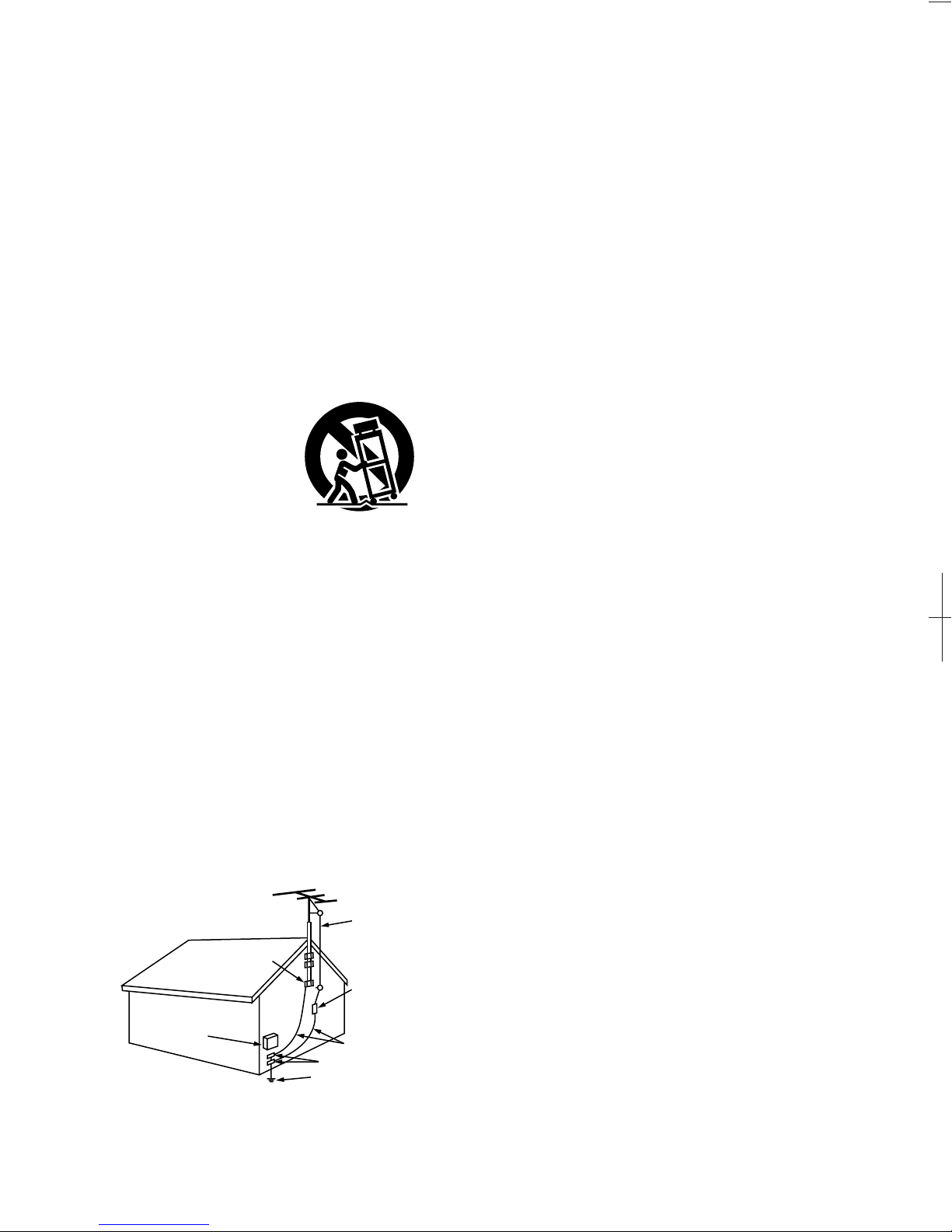
6. Carts and Stands – The appliance should be used only with
a cart or stand that is recommended by the manufacturer.
6A. An appliance and cart
combination should be
moved with care.
Quick stops, excessive
force, and uneven
surfaces may cause
the applicance and cart
combination to overturn.
7. Wall or Ceiling Mounting – The appliance should be
mounted to a wall or ceiling only as recommended by the
manufacturer.
8. Ventilation – The appliance should be situated so that its
location or position does not interfere with its proper
ventilation. For example, the appliance should not be
situated on a bed, sofa, rug, or similar surface that may
block the ventilation openings; or, placed in a built-in
installation, such as a bookcase or cabinet that may
impede the flow of air through the ventilation openings.
9. Heat – The appliance should be situated away from heat
sources such as radiators, heat registers, stoves, or other
appliances (including amplifiers) that produce heat.
10. Power Sources – The appliance should be connected to a
power supply only of the type described in the operating
instructions or as marked on the appliance.
11. Grounding or Polarization – Precautions should be taken so
that the grounding or polarization means of an appliance is
not defeated.
12. Power-Cord Protection – Power-supply cords should be
routed so that they are not likely to be walked on or
pinched by items placed upon or against them, paying
particular attention to cords at plugs, convenience
receptacles, and the point where they exit from the
appliance.
14. Cleaning – The appliance should be cleaned only as
recommended by the manufacturer.
15. Power Lines – An outdoor antenna should be located away
from power lines.
16. Outdoor Antenna Grounding – If an outside antenna is
connected to the receiver, be sure the antenna system is
grounded so as to provide some protection against voltage
surges and built-up static charges. Article 810 of the
National Electrical Code, ANSI/NFPA 70, provides
information with regard to proper grounding of the mast
and supporting structure, grounding of the lead-in wire to
an antenna-discharge unit, size of grounding conductors,
location of antenna-discharge unit, connection to grounding
electrodes, and requirements for the grounding electrode.
See Figure A.
17. Nonuse Periods – The power cord of the appliance should
be unplugged from the outlet when left unused for a long
period of time.
18. Object and Liquid Entry – Care should be taken so that
objects do not fall and liquids are not spilled into the
enclosure through openings.
19. Damage Requiring Service – The appliance should be
serviced by qualified service personnel when:
A. The power-supply cord or the plug has been damaged;
or
B. Objects have fallen, or liquid has been spilled into the
appliance; or
C. The appliance has been exposed to rain; or
D. The appliance does not appear to operate normally or
exhibits a marked change in performance; or
E. The appliance has been dropped, or the enclosure
damaged.
20. Servicing – The user should not attempt to service the
appliance beyond that described in the operating
instructions. All other servicing should be referred to
qualified service personnel.
FIGURE A
EXAMPLE OF ANTENNA GROUNDING
AS PER NATIONAL
ELECTRICAL CODE ANTENNA
LEAD IN
WIRE
GROUND
CLAMP
ELECTRIC
SERVICE
EQUIPMENT
ANTENNA
DISCHARGE UNIT
(NEC SECTION 810-20)
GROUNDING CONDUCTORS
(NEC SECTION 810-21)
GROUND CLAMPS
POWER SERVICE GROUNDING
ELECTRODE SYSTEM
(NEC ART 250, PART H)
NEC - NATIONAL ELECTRICAL CODE
Printed in Japan 511 3345 000 808
DENON SERVICE NETWORK
•Please contact one of our overseas service centers, listed below, for follow-up service consultation.
•
Wenden Sie sich für anfallende Wartungs-bzw. Reparaturarbeiten bitte an eine der folgend aufgeführten Kundendienststellen.
•Adressez-vous à nos centres de service d’outre-mer indiqués ci-dessous, pour le service aprèsvente.
•Per il servizio dopo vendita rivolgete Vi al nostro centro di servizio estero appropriato della lista seguente.
•Para consultas de servicio porfavor dírigirse a cualquiera de nuestros centros de servicio en el extranjero, enlistados abajo.
•Neem kontakt op met één van onze reparatie-inrichtingen in het buitenland, waarvan hier een lijst volgt, voor na-service.
•Ta kontakt med nedan angivna servicecentraler för rådfrågning om servicearbeten efter försäljningen.
•
Favor contactar um de nossos centros de serviços internacionais, abaixo listados, para consulta de serviços de acompanhamento.
Australia AWA Audio Products Pty Ltd. 67 O’Riordan Street, Alexandria NSW 2015, Australia
Tel: (02) 9669-3477 Fax: (02) 9578-0140
Austria Digital-Professional-Audio Vertriebsges.m.b.H., 1170 Wien, Rupertusplatz 3
Tel: 0222-4501006~9, Fax: 0222-457679
Belgium Transtel-Sabima P.V.B.A. Harmoniestraat 13, 2018 Antwerpen 1, België Tel: 03-237-3607
Canada Denon Canada Inc. 17 Denison Street, Markham Ontario, Canada L3R 1B5 Tel: 905-475-4085 Fax: 905-475-4159
China Shanghai Denon Products Service Co., Ltd. Room 1504, A Building 527 Huaihai Zhong Road,
Shanghai 200020, P.R.C. Tel: (021)53062078
Czecho EUROSTAR OSTORAVA s.r.o. Za Vokovikou vozovnou 369/5, 161 00 Praha 6
Tel: 2-316-3690 Fax: 2-316-6852
Denmark Hifi Klubben A/S Dali Alle 1, 9610 Noerager, Denmark Tel: 45-96 72 10 00 Fax: 45-96 72 10 14
Finland Suomen Hi-Fi Klubi OY Nylandsgatan 4-6, Helsingfors Tel: 0644401
France Denon France S.A. 3 Boulevard Ney, 75018 Paris Tel: 44-89-68-69
F.R. Germany Denon Electronic GmbH Halskestraße 32, 40880 Ratingen Tel: 02102-4985-0
Greece KINOTECHNIKI LTD. 47 Stournara Str., Athens Tel: 380-6998
Hong Kong Denon Hong Kong Ltd., 11/F North, Somerset House 979 King’s Road, Quarry Bay, Hong Kong
Tel: 2516-6862, Fax: 2516-5940
Iceland Japis Ltd. Brautarholt 2, Box 396, 121 Reykjavik, Iceland Tel: 5625200
Indonesia PT Autoaccindo Jaya. Cideng Barat No. 7 Jakarta, Indonesia Tel: 633-2730
Italy Professional Equipment srl. 20142 Milano v.le Famagosta 37, Italy Tel: 02-89.10.241 Fax:02-81.38.032
Korea DAIYOUNG Industrial Co.,Ltd. 1027-5, Bangbae-dong, Seocho-gu, Seoul 137-060 Korea
Tel: 02-588-3960 Fax: 02-586-3721
Malaysia Pertama Audio (PJ) Sdn. Bhd. 38, 40 & 42 Jalan PJS 11/28A Sunway Metro Bandar Sunway 46510
Selangor, Malaysia Tel: 03-7378888 Fax: 03-7378188
Mexico Labrador, S.A. de C.V. Zamora No. 154 Col. Condesa 06140 Mexico, D.F. Tel: 286 55 09 Fax: 286 34 62
Netherlands Penhold B.V. Poppenbouwing 58, NL-4191 NZ Geldermalsen, Netherland Tel: 31-345-588 080 Fax: 31-345-588 085
New Zealand Avalon Audio Corpn. Limited 119 Wellesley Street, Auckland 1, New Zealand Tel: 09-779-351, 09-775-370
Norway Hi-Fi Klubben Box 70 Ankertorget, 0133 Oslo 1 Tel: 02-112218
Poland HORN DISTRIBUTION ul. Nowoursynowska 131R (wjazd od ul. Rosota) 02-975 Warszawa
Tel: 22-649-3071 Fax: 22-649-3199
Portugal Videoacustica Qta. Do Paizinho-Armazém 5-Estrada De Circunvalação-Apart. 3127 1303 Lisboa Codex
Tel: 2187004/2187096
Singapore Denon Electronics Singapore Pte Ltd. 257 Selegie Road #03-257 Selegie Complex
Singapore 188350 Tel: 65-339-1181 Fax: 65-339-8366
Spain Gaplasa S.A. Conde de Torroja, 25, 28022 Madrid Tel: 91-329-42-63
Sweden Sveriges Hi-Fi Klubb Box 5116, S-402 23 Göteborg Tel: 031-200040
Switzerland Diethelm & Co., AG. Grindelstrasse 5, 8303 Bassersdorf Tel: 01-838-1611
Taiwan R.O.C. Taiwan Kolin Co., Ltd. 10th Fl., 86, Sec. 1, Chung-king S. Rd., Taipei, Taiwan R.O.C.
Tel: (02) 314-3151 (20 Lines) Fax: (886) 02-3614037 Telex: 11102 TKOLIN
Thailand Mahajak Development Co., Ltd. 6th Fl., Mahajak Building, 46 Sukhumvit 3 (Nananua), Klongteoy,
Prakranong, Bangkok 10110 Tel: 256-0020
United Hayden Laboratories Ltd. Hayden House, Chiltern Hill, Chalfont St.
Kingdom & Eire Peter Gerrards Cross, Bucks, SL9 9UG Tel: 01753-888447
U.S.A. DENON ELECTRONICS, a Division of Deonon Corporation (U.S.A.) 222 New Road Parsippany,
NJ07054, U.S.A., Tel: 973-575-7810, Fax: 973-575-1213
*If there is no service center in your local area, consult the outlet where the equipment was purchased.
*Falls sich in Ihrer Nähe keine Kundendienststelle befindet, wenden Sie sich an das Geschäft, wo das Gerät gekauft wurde.
*S’il n’y a aucun centre de service dans votre région, consultez votre revendeur.
*Se nella Vostra zona non c’è il centro di servizio, rivolgete Vi al negozio dove avete acquistato l’apparecchio.
*Si no hay centros de servicio en su área local, consulte en donde haya comprado su equipo.
*Als er in uw streek geen reparatie-inrichting is, neemt u kontakt op met de vestiging waar u de apparatuur gekocht heeft.
*Saknas servicecentral i närheten där du bor, bör kontakt tas medåterförsäljaren för apparaten.
*Se não existir um centro de serviços em sua área local, consulte o estabelecimento onde o equipamento foi adquirido.
*G80801
14-14, AKASAKA 4-CHOME, MINATO-KU, TOKYO 107-8011, JAPAN
Telephone: (03) 3584-8111
Cable: NIPPON COLUMBIA TOKYO Telex: JAPANOLA J22591

NOTE ON USE
A
void high temperatures
Allow for sufficient heat dispersion
when installed on a rack.
Handle the power cord carefully. Hold
the plug when unplugging the cord.
Keep the set free from moisture,
water, and dust.
Unplug the power cord when not
using the set for long periods of time.
"(For sets with ventilation holes)
Do not obstruct the ventilation holes.
Do not let foreign objects in the set.
Do not let insecticides, benzene, and
thinner come in contact with the set.
Never disassemble or modify the set
in any way.
4

Thank you very much for purchasing the DENON component stereo
cassette tape deck.
DENON proudly presents this advanced tape deck to audiophiles and
music lovers as a further proof of DENON's non compromising pursuit of
the ultimate in sound quality. The high quality performance and easy
operation are certain to provide you with many hours of outstanding
listening pleasure.
- TABLE OF CONTENTS -
FEATURES ....................................................................................... 5
CONNECTION ................................................................................... 5
NAMES AND FUNCTION OF PARTS ................................................. 6, 7
CASSETTE TAPES ............................................................................. 7
AUTOMATIC TAPE SELECTION .......................................................... 8
PLAYBACK ........................................................................................ 8
RELAY PLAY ..................................................................................... 9
TWIN OUTPUT ................................................................................. 9
MUSIC SEARCH SYSTEM ................................................................... 9
RECORDING ................................................................................... 10
PROPER RECORDING LEVEL ............................................................ 10
REC/REC MUTE AND REC PAUSE BUTTON ........................................ 10
AUTO-STANDBY ............................................................................. 11
TWIN RECORDING ......................................................................... 11
RELAY RECORDING ........................................................................ 11
DUBBING ....................................................................................... 12
DECK A/B SELECT AND MEMORY STOP ............................................ 13
DOLBY B AND C NOISE REDUCTION SYSTEM ................................... 14
DOLBY HX-PRO HEADROOM EXTENSION SYSTEM ............................ 14
MAINTENANCE ............................................................................... 14
TROUBLESHOOTING ....................................................................... 15
SPECIFICATIONS ............................................................................ 15
WIRED REMOTE DIAGRAM............................................................... 16
CONNECTION
Please check to make sure the followin
g
items are included with
the main unit in the carton:
(1) Operating Instructions ......................................................... 1
(2) Connection Cords ................................................................ 2
(3) Remote control box connection wire ..................................... 1
(4) Remote control box schematic diagram ................................ 1
FEATURES
• Computer Controlled Mechanism
• Dual Power Supply
• Dolby HX-Pro Headroom Extension System (deck B only)
• Dolby B & C Noise Reduction Systems (A/B Independent)
• Computing Tape Counter with 4-Digit Readout and Memory
Stop
•Music Search System
• FL Peak Level Meters
• Auto Tape Selector
• 2-Speed Dubbing
•Relay Playback
• Twin Recording and Relay Recording
•19-inch Rack Mountable
• Speed Control of Approximately ±12% (A/B Independent)
• Accurate Music Search System
• Display Memory Back-up
•Twin Output
•
A
uto-standb
y
Leave your entire system (including this cassette deck) turned off
til
all connections between the deck and other components have been
completed.
•Connecting the Deck to an Amplifier (Mixer)
Before connecting the deck to your amplifier, please review your
amplifier's instruction manual. Use the white plugs for the left
channel and red plugs for the right channel.
•Tape Dubbing
Many stereo amplifiers and receivers have tape dubbing circuitry
so that tape duplication can be performed between two or more
tape decks. Review your amplifier's instruction manual for a full
explanation of this mode of operation.
•Connecting Headphones
To listen through headphones, plug your headphones into the
PHONES jack.
• Installation Precautions
If the deck is placed near an amplifier, TV or tuner, noise (induced
hum) or beat interference may result, especially during FM or AM
reception. If this occurs, place the deck further away from other
components or reorient its position.
5

NAMES AND FUNCTIONS OF PARTS
Recording without Dolby NR
Recording with Dolby NR type B
(The "B" indicator will light up.)
Recording with Dolby NR type C
(The "C" indicator will light up.)
The DN-770R uses independent Dolby NR systems for decks A and B. Set the Dolby NR type for both decks A and B, using
the deck A/B selector O to switch between the decks.
Dubbing Speed Buttons (DUBBING SPEED)
Pressing the NORMAL button starts regular speed dubbing from deck A to deck B.
Press the HIGH button to perform dubbing at double speed. See page 12.
Tape Speed B Control (TAPE SPEED-B)
Use this knob to vary the tape speed. The speed can be varied within a range of
approximately ±12% according to the position of the tape speed control knob.
Input Level Control (INPUT LEVEL)
This knob adjusts the recording input level. It affects the level in both channels. See
page 10.
Cassette Compartment Cover
If the cover is not closed completely, the tape transport buttons will remain
inoperative.
Headphone Jack (PHONES)
For private music enjoyment without disturbing others, or for monitoring a
recording, a headphone set may be connected to this jack. Use a headphone with
an impedance rating of 8 to 1200 ohms. Signals are output according to the position
of the Deck A/B selector.
During dubbing, sound is produced from deck A only, regardless of the position of
the deck A/B selector.
Reverse Mode Switch (REV. MODE)
Select the type of tape transport. The reverse mode can be set to
(one side), (continuous playback), RELAY (relay playback).
Twin Recording Button (TWIN REC)
Pressing this button will set both deck A and B to the recording pause mode. See
page 11.
Power Switch (POWER)
Press once to turn the power to deck on, and once more to turn the power off.
The deck remains in a stand-by (non-operative) mode for approximately 2 seconds
after it is switched on.
Eject Button (EJECT)
Press this button to open the cassette compartment cover. When the tape is
running, press the STOP button first to stop tape transport, then press the Eject
button.
Counter Reset Button (COUNTER RESET)
Press this button to reset the tape counter to zero.
Deck A/B Selector (DECK A/B)
Press this button to switch the display between deck A and deck B.
Counter Memory Button (MEMO)
When this button is pressed during forward tape travel, fast rewinding will stop
automatically at the tape counter position "0000".
When this button is pressed during reverse tape travel, fast forwarding will stop
automatically at the tape counter position "0000". See page 13.
Tape Speed A Control (TAPE SPEED-A)
Use this knob to vary the tape speed. The speed can be varied within a range of
approximately ±12% according to the position of the tape speed control knob.
Dolby NR Button (DOLBY NR)
Press the DOLBY NR button and select the Dolby NR type that suits the recording.
6

PLAY Play Button Press to playback tape.
■Stop Button Press to stop the tape in any mode.
<< Fast Rewind Button Press for fast rewind.
>> Fast Forward Button Press for fast forwarding.
REC/REC MUTE Rec/Rec Mute
Button
Press the REC/REC MUTE (•) button and PLAY button simultaneously to start
recording. If only the REC/REC MUTE (•) button is pressed, the deck enters the
Recording Pause mode. Pressing this button in the Recording Pause mode will start
Auto Rec Mute, and a 5-second silent space is recorded onto the tape. See page 11.
REC PAUSE Rec Pause Button Press this button to enter the recording pause mode from the recording or recording
mute mode. This button can only be used during recording. See page 11.
◄► Direction Button Changes the tape transport direction from forward "►" to reverse "◄", and vice versa.
Display
Indicators with an encircled number light up when the corresponding button is
pressed.
CASSETTE TAPES
• Handling Precautions
• C-120 Cassettes
C-120 cassette tapes are not recommended as they use a very thin tape base which
may become tangled around the capstan or pinch roller.
• Tape Slack Before putting a tape into the deck, take up any slack with a pencil or
your finger tip. This precaution prevents the tape from becoming entangled around
the capstan or pinch roller.
• Storage Precautions
• Do not store cassette tapes in a place where they will be subject to:
• Extremely high temperature or excessive moisture
• Excessive dust
• Direct sunlight
• Magnetic fields (near TV sets or speakers)
• To eliminate tape slack, store your cassettes in cassette cases with hub stops
• Accidental Erasure Prevention
• All cassettes have erasure prevention tabs for each side. To protect valuable
recordings from accidental or inadvertent erasure, remove the tab for the appropriate
side with a screwdriver or another tool.
• To record on a tape whose erasure prevention tabs have been removed, cover the
tab holes with adhesive tape.
T
ape Transport Buttons
7

A
UTOMATIC TAPE SELECTION
This Stereo Cassette Deck contains an automatic tape selector which automatically selects
the optimum bias and equalization for the tape in use. This is accomplished by detection of
the tape type detections holes in the cassette housing.
PLAYBAC
K
• If a tape without tape type detection holes is used, the deck will be set for
normal tapes.
• The operations described below apply to deck A and deck B alike.
• Switch on your amplifier or receiver.
• Set the Tape Monitor switch on your amplifier or receiver to the TAPE position.
• The numbers in the illustration below depict the order in which operation steps are
carried out.
Press the POWER switch to the ON position.
Press the EJECT button to open the cassette compartment cover.
Load the cassette tape and close the cassette compartment cover.
When listening to a tape that has been recorded with Dolby noise reduction, set the
DOLBY NR button to match the system used at the time of recording.
Pressing the DOLBY NR button selects Dolby noise reduction type B
(and the "B" indicator lights up).
One more press of the DOLBY NR button selects Dolby noise reduction type C
(and the "C" indicator lights up).
Pressing the DOLBY NR button once again switches Dolby noise reduction off.
Press the PLAY button to begin playback. The PLAY (4 or D) indicator
will light during playback.
Press the stop button to stop the playback.
• In the continuous playback mode (REVERSE MODE), playback
of both tape sides will be repeated 5 times and then stop
automatically.
• If different types of Dolby noise reduction are used for record and
playback, playback response will be adversely effected.
• When power is turned off during tape transport, it may not be possible to remove the
cassette by pressing the EJECT button. In this case, turn on power again before you
press the EJECT button.
8

RELAY PLAY (continuous playback of the tapes in deck A and deck B)
• Load a cassette tape into deck A and B, and set the Dolby NR button
correctly on deck A and B.
9
•MUSIC SEARCH SYSTEM
The music search system detects blank sections (lasting for at least 4 seconds) between
selections in order to locate the beginning of selections in the forward or reverse direction.
1. To advance from the current selection to the beginning of the next
selection (CUE):
Press the PLAY button simultaneously with the Fast Forward button when the tape is
traveling in the forward direction. Press the PLAY button simultaneously with the
Rewind button when the tape is traveling in the reverse direction.
The deck will skip the rest of the current selection and automatically resume play from
the beginning of the next selection.
2. To repeat playback from the beginning of the current selection:
Press the PLAY button simultaneously with the Rewind button when the tape is traveling
in the forward direction. Press the PLAY button simultaneously with the Fast Forward
button when the tape is traveling in the reverse direction.
The deck will rewind the tape to the beginning of the current selection and
automatically resume play from that point.
This is very convenient for repeating playback of the current selection.
Notes on Music Search Operation:
The search functions operates by detecting comparatively long, blank sections
approximately 4 to 5 seconds long, in between recorded selections. Therefore, the system
may not operate normally in the following cases:
• Recordings with discontinuous speech or conversation.
• Recordings with long periods of pianissimo (softly played music).
• Recordings with long silences.
• Blank sections with a high level of noise.
• Blank sections shorter than 4 seconds.
• If noise-emitting appliances, such as electric razors, drills, refrigerators,
etc., are operated nearby.
• REV close the beginning of the program or CUE close to the ending.
REVERSE MODE set to "RELAY".
Press the PLAY button of the deck you first wish to listen to.
The PLAY indicator of the deck playing back the tape will light up. ~3
To stop relay play, press the stop button of the deck currently
playing the tape.
• Relay play will play decks A and B in succession for 5 cycles, upon which playback
stops. When playback starts from deck B, when switching to deck A, the first deck
A playback cycle will be counted as the second cycle. The completion of 5 cycles
will always be at the opposite side of the tape in deck B.
NOTE: If both decks A and B are set to the play or record modes while in the relay mode,
the relay mode is cancelled and the RELAY indicator turns off. To set the relay
mode again, first set both decks A and B to the stop mode.
The RELAY indicator turns back on.
• TWIN OUTPUT
With the DN-770R, it is possible to play tapes simultaneously on decks A and B and
output their signals at the same time.
When both decks A and B are played, the signals for deck A are output from the deck A
line out jacks, and the signals from deck B are output from the deck A/B line out jacks.
• The deck A line out jacks are exclusively for the deck A signals.
• The deck A/B line out jacks are for both the deck A and deck B signals.
• Use the deck A/B line output jacks when connecting one of the sets of
line outputs to a receiver or amplifier.

RECORDING
The operations described below apply to deck A and deck B alike. Switch on your
amplifier or receiver and the source component. Set the Tape Monitor switch on your
amplifier or receiver to the SOURCE position.
Press the POWER switch to the ON position.
Load the cassette tape.
(Check that the erasure prevention tabs of the cassette housing have
not been broken off.)
Press the DOLBY NR button and select the Dolby NR type that suits the
recording.
Press the Direction (◄►) button to select the direction of tape transport.
Select the type of tape transport with the REVERSE MODE switch.
Mode Switch Setting
To record on only one side
To continuously record
on both sides
or RELAY
• PROPER RECORDING LEVEL
A too high recording level can saturate the tape and cause distortion.
On the other hand, if the recording level is set too low, soft passages
will be marked by residual noise. A proper recording level is the single
most important factor for making well balanced recordings.
Guideline for maximum recording level
TYPE I (Normal) 0 dB level on peaks
TYPE II (Cr02) +1 dB level on peaks
TYPE IV (Metal) +3 dB level on peaks
Press the REC/REC MUTE (•) button to set the recording pause mode.
The •II indicator will light up.
Adjust the recording level with the INPUT LEVEL control while watching
the Peak Level Meter.
Press the PLAY button to start the recording.
The PLAY (◄or►) and the •indicator will light during recording.
To stop recording, press the stop button.
To pause the recording, press the REC PAUSE (II) button. Press the
PLAY button to resume recording.
Caution:
• Be careful not to erase important recordings by mistake. Inadvertent
start of recording will happen in the following cases:
1. If the PLAY button is pressed while the 1 indicator lights, recording
starts.
2. If the PLAY and REC/REC MUTE (•) button are pressed at the same
time, recording starts.
The best way to avoid accidental erasure is to break off the two erasure
prevention tabs on the cassette housing.
10
Note: The optimum recording level differs depending on the program
source and the type of tape used.
• REC/REC MUTE AND REC PAUSE Button
1. To record a 5-second blank section during recording:
Press the REC/REC MUTE (•) button. A 5-second blank will be
recorded and the deck will enter the recording standby mode.
2. To record a 5-second blank section during the recording standby mode: Press the
REC/REC MUTE (•) button from the recording standby mode. A 5 second blank will be
recorded and the deck will enter the recording standby mode again.
3. To cancel recording of blank space:
Press the REC PAUSE (II) button. Blank space recording will be
cancelled and the deck enters the recording standby mode.
4. To extend the blank section with another 5 seconds or more:
Simply press the REC/REC MUTE (•) button and the blank section will be increased
with another 5 seconds.

• AUTO-STANDBY
This function is extremely convenient when conducting relay recording, relay
playback, twin recording or tape copying.
• When the fast rewind (<<) and record pause (II) buttons are pressed
simultaneously while in the stop mode and the tape is set to play in the forward
direction (►), the tape is rewound to the beginning, then played to the end of the
leader tape and stopped automatically at the beginning of the magnetic tape.
• When the fast forward (>>) and record pause (II) buttons are pressed
simultaneously while in the stop mode and the tape is set to play in the reverse
direction (◄), the tape is fast-forwarded to the end, then played in the reverse
direction to the end of the leader tape and stopped automatically at the beginning of
the magnetic tape.
• The PLAY indicator flashes during the auto-standby mode.
Caution:
If recording is started after using the auto standby function with a recorded tape, the sound
of the previous recording may not be completely erased. In such cases, rewind the tape
before starting to record.
• TWIN RECORDING (simultaneous recording on deck A and deck B)
This is a convenient feature for recording the same program source onto two tapes at
the same time.
• Load cassette tapes into both deck A and B. Set the Dolby NR button both deck A and B
and the REVERSE MODE switch.
Press the TWIN REC button. The A+B indicator will light up and both
decks will enter the recording pause mode.
Adjust the INPUT LEVEL control for the best recording input levels while watching the
Peak Level Meter.
Press the PLAY button of deck B to start twin recording.
To stop twin recording, press the STOP button of each deck.
• RELAY RECORDING (continues recording from deck A to deck B)
To record a long program, start recording on deck A, and when both sides of the tape
in deck A have been recorded, the relay recording feature continues to record on the
tape in deck B.
• Load cassette tapes into decks A and B, and set the Dolby NR button both deck A/B.
• By pressing the deck B REC PAUSE (II) button or the REC/REC MUTE (•) button,
the recording pause or recording mute mode on both decks can be set automatically.
The deck A (II) and (•) buttons cannot be used.
• The relay mode cannot be set with the REVERSE MODE switch when in the twin
recording mode.
Adjust the INPUT LEVEL control for the best recording input level while watching the
Peak Level Meter.
Press the PLAY button of deck A to start relay recording.
To stop relay recording, press the STOP button of the deck that is recording.
NOTE: If both decks A and B are set to the play or record modes while in the relay mode,
the relay mode is cancelled and the RELAY indicator turns off. To set the relay
mode again, first set both decks A and B to the stop mode.
The RELAY indicator turns back on.
11

12
DUBBING
(from deck A to deck B)
• Switch on the amplifier or receiver.
• Set the Tape Monitor switch on your amplifier or receiver to the TAPE position.
Press the POWER switch to the ON position.
load the cassette tape to be played in deck A and the one to be recorded in deck B.
Select the type of tape transport with the REVERSE MODE switch.
Reverse mode Operation
Dubbing is performed only for one side.
The decks stop when either deck A or B
reaches the end of the tape.
The tape direction is reversed on each
deck when they reach the end of the tape.
(This is convenient for dubbing to a tape
with a different length.)
RELAY During dubbing of the side facing you, the
deck that first reaches the end of the tape
will stand by until the other deck reaches the
end of the tape, then both decks will reverse
the tape direction together.
(Depending on the manufacturer, the length of
tapes having the same recording time may differ
somewhat. Setting this mode permits the arrangement
of the beginning portion of the opposite
side of the tape.)
To begin normal speed dubbing, press the DUBBING SPEED NORMAL button. The DUB
indicator will light at this time.
To high speed dubbing, press the DUBBING SPEED HIGH button. The HIGH indicator
will light at this time.
To stop dubbing, press the stop of deck A or deck B.
• When deck A is in the playback mode and deck B is in the stop condition, setting deck B
to the recording pause mode will engage the normal speed dubbing pause mode.
Dubbing is then started by pressing the PLAY button.
• When dubbing, the recording level and the Dolby NR coding will be the same as those
of the playback tape, regardless of the positions of the INPUT LEVEL control and the
DOLBY NR button.
• When listening to the playback sound during normal speed dubbing, set the DOLBY NR
button to match the Dolby NR system with which the playback tape was recorded. This
will assure correct sound reproduction, but does not affect the recording.
• The playback sound cannot be heard during high speed dubbing.
Operation using the REC/REC MUTE (•) and REC PAUSE (II) buttons of deck B is
permitted during normal speed dubbing.
• Buttons other than the stop button cannot be used during high speed dubbing.

13
1) Operation of the Deck A/B Selector
(1) Press the RESET button to reset the counter to "0000".
(2) By using the PLAY, FF, or REW functions, the reading of the
counter will change to indicate index position.
• During recording and playback operations, the counter is useful for noting the
location of existing programs or positions where recording is to be started.
• The reading of this counter does not correspond with that of any other deck.
(3) Deck A and Deck B have the memory of their own counter. Operate COUNTER A/B
to change Deck A or B to display its counter.
(4) The level meter and Dolby setting display also switch with the
Deck A/B selector.
2) MEMORY STOP Operation
(1) During recording or playback, the Memory Stop feature can be used to locate a
particular point on the tape. Press the COUNTER MEMO button at the desired
point.
(2) The MEMO indicator lights.
(3) When the Rewind (<<) is pressed during forward tape travel (►), or the Fast
Forward (>>) button is pressed during reverse tape travel (◄), the tape is
rapidly rewound (or advanced) until the counter indication of "0000" is reached.
• The Memory Stop feature will rewind or forward the tape to within -5 counts in
the forward (►) direction (from "0000" to "-0005") and to within +5 counts in
the reverse (◄) direction (from "0000" to "0005"). After this, several seconds
are required for corrective operations.
• The Memory Stop function operates independently in both directions for deck A
and deck B. The MEMO indicator will switch over with the use of the DECK A/B
button.
Caution:
If the memory stop operation is performed after repeated fast
forwarding or rewinding, the tape may not stop at the proper position.
(3) Display Back-up
(1) The COUNTER VALUE, DECK A/B, MEMO DIRECTION and DOLBY NR functions are
protected for approximately one month by a memory back-up.
Once the back-up period is up, the DOLBY NR and MEMO settings are set to off,
the DECK A/B setting is reset to "A" the DIRECTION setting is set to (►), and
the counter is reset to "0000".
DECK A / B SELECT AND MEMORY STOP

DOLBY B AND C NOISE REDUCTION SYSTEM
• The Dolby noise reduction system substantially reduces the tape background noise (hiss)
inherent in the cassette medium. Dolby B NR is most widely in use. However Dolby C NR
is a much more recent development and represents significant improvements over Dolby
B NR.
• Tape background noise consists primarily of high frequency information, which is
particularly annoying during soft passages. The Dolby NR system increases the level of
low volume mid- and high-frequency signals during recording and reduces the level of
these signals by an identical amount during playback. As a result, the playback signal is
identical to the original source, but the level of background noise generated by the tape is
greatly reduced.
DOLBY HX-PRO HEADROOM EXTENSION SYSTEM
This deck is equipped with the Dolby HX-PRO headroom extension system. Since the system
functions automatically during recording, no switching operation or adjustment is required.
The system is effective with any type of Normal, Cr02 and Metal tape.
The Dolby HX-PRO headroom extension system functions during recording to raise the
saturation level in the treble range. Therefore, most of the treble range components distorted
or lost during recording on conventional cassette decks are more faithfully recorded on the
new DENON cassette deck.
MAINTENANCE
• Head Cleaning
After long usage, tape coating or dust may adhere to the heads, causing deterioration
of sound. Therefore, the parts depicted in the illustration should be cleaned regularly.
Use a cotton swab moistened with a tape head cleaning solution (such as alcohol).
Note:
1. Some cleaning cassettes on the market have strong abrasive effects and may scratch
the heads. Always use cotton swabs instead of cleaning cassettes.
2. Since the use of metal tape is apt to collect more dust on the heads, the heads should
be cleaned more often to enjoy the best possible sound.
14
• The operating principle of Dolby C NR is similar to that of Dolby B NR except for the
encoding /decoding response curves. The noise reduction effect obtained with Dolby C
NR is up to 20 dB, compared to 10 dB with Dolby B NR. In addition, Dolby C NR uses an
anti-saturation network and spectral skewing circuitry for a significant improvement in
the dynamic range of the mid- to high-frequencies.
Features of the Dolby HX-PRO Headroom Extension System
(1) Performance of Normal and Cr02 tapes can be improved to very close of that offered by
Metal tape.
(2) The dynamics in the treble range are improved significantly.
(3) Since no decoding is necessary during playback, the improved sound can be enjoyed on
any type of tape deck, including portable players and car audio systems.
(4) The system functions whether the Dolby B/C NR system is engaged or not.
• Cleaning the Pinch Rollers and Capstans
If the pinch rollers or capstans accumulate dust, tape transport may become unstable,
as a result from slippage, during recording or playback. The tape can also be damaged
if it gets entangled in the capstan.
Clean these parts with a cotton swab or a soft cloth moistened with a tape head
cleaning solution (such as alcohol).
• Demagnetizing the Heads
The heads will become magnetized after long usage or if strongly magnetized objects
are brought near them. The result is a generation of noise, loss of the high frequency
range, and in extreme cases erasure of treble components on pre-recorded tapes in
combination with added noise.
Thus, the heads should be demagnetized at regular intervals. (Head demagnetizers are
separately available from your dealer.)
• How to Demagnetize the Tape Heads
1. Turn off the power.
2. Turn on the demagnetizer while it is at least 30 cm away from the heads. Bring the
demagnetizer near the heads and slowly move it in small circles four or five times in
front of each head, making sure you do not touch them.
3. Slowly move the demagnetizer away and turn it off when it is at
least 30 cm away from the heads.

TROUBLESHOOTING
Check the following before you draw the conclusion that your Stereo Cassette Deck is malfunctioning. 1. Are all the connections correct? 2. Are all system components being operated
correctly in accordance with the operating instructions? 3. Are the speakers and amplifier/ receiver functioning correctly? If the tape deck still does not function properly, check the symptom
against the list below. If the symptom does not correspond to the check list, please contact your DENON dealer.
Problem Cause Remedy
Tape does not run • Power cord is disconnected. • Check power cord.
• Tape is loose. • Tighten tape with a pencil, etc.
• Cassette is not loaded properly. • Load cassette properly.
• Defective cassette. • Replace cassette.
Tape is not recorded when REC/REC MUTE ( • ) • No cassette is loaded. • Load cassette.
button is pressed. • Erase prevention tabs are broken off. • Cover holes with adhesive tape.
Sound is warbled and distorted. • Heads, capstan or pinch roller are dirty. • Clean them.
• Tape is wound too tight. • Fast forward or rewind to loosen tape
winding.
• Recording input level is too high. • Adjust recording input level.
• Tape is worn out and has "drop-outs". • Replace tape.
Excessive noise • Tape is worn. • Replace them.
• Heads, capstan or pinch roller are dirty. • Clean them.
• Heads are magnetized. • Demagnetize heads.
• Recording input level is too low. • Adjust recording input level.
High frequency range (treble) is emphasized. • Dolby NR switch is set improperly. • Set Dolby NR Switch properly.
High frequency range (treble) is lost. • Heads are dirty. • Clean them.
• Tape is worn. • Replace tape.
The cassette tape cannot be removed. • If the POWER switch is turned off either • Turn the POWER switch ON again, and
during recording or playback and the unit is then press the STOP button.
stopped, there may be cases when the • Now, press the EJECT button to
cassette cannot be removed, even if the remove the cassette tape.
EJECT button is pressed.
SPECIFICATIONS
* Above specifications and design are subject to change without prior notice.
Dolby noise reduction and HX Pro headroom extension manufactured under license from Dolby Laboratories Licensing Corporation. HX Pro originated by
Bang & Olufsen. .
"DOLBY", the double-D symbol and "HX PRO" are trademarks of Dolby Laboratories Licensing Corporation.
15
Type Vertical tape loading; 4-track 2-channel
stereo double cassette deck
Heads Recording/ playback head (Amorphous) x 2
Erase head (Double-gap ferrite) x 2
Motors Capstan (DC servo motor) x 2
Real (DC motor) x 2
Tape Speed 4.8 cm/ sec.
Variable (PLAY) Approx. ±12%
Fast Forward,
Rewind Time Approx. 110 sec. with a C-60 cassette
Recording Bias Approx 105 kHz
Overall S/ N Ratio
(at 3% THD level) Dolby C NR on: more than 74 dB (CCIR/ARM)
Overall Frequency
Response 20 --- 18,000 Hz ±3 dB (at-20 dB, Metal tape)
Channel Separation More than 40 dB (at 1 kHz)
Wow & Flutter 0.06% WRMS, ±0.14% w. peak
Input
LINE 80 mV (-20 dBm) input level at maximum
Input impedance: 50 kohm unbalanced
Output
LINE 775 mV (0 dB) output level at maximum
(with 47 kohm load, recorded level of
200 pwb/mm)
PHONES 1.2 mW output level at maximum
(optimum load impedance 8 ohm ~ 1.2
kohm)
Power Supply Voltage is shown on rating label
Power Consumption Show on rating label
Dimensions 4831W1 x 134 (H) x 2751D) mm
(17-3/32" x 4-57/64" x 10-53/64")
Weight 5.4 kg (9 Ibs 11 oz)

WARNING:
INSTRUCTIONS ON THIS SHEET ARE FOR QUALIFIED SOUND INSTALLERS AND SERVICE PERSONNELS ONLY.
Wired Remote Control Box Circuit Diagram
L - CH : Vcc (5 VOLT)
R - CH : SIGNAL
SW001 ~ 008: Momentary Contact
SW101, 102: Toggle Switch
Second and Subsequent Units
SW 008 DECK A/B
DECK SELECTOR button
Press this button to select either Deck A or Deck B to be
controlled.
• Make a control box using the supplied remote control box connection wire.
• Do not connect the left channel of the plug (Vcc) with 8001 (200 ohm) in the second and subsequent units.
• Use resistors having a tolerance of within ±5% (1 /4W).
Use of resistors having a poorer tolerance will cause incorrect operation.
• Never short circuit the left-channel line (Vcc). Doing so will damage the main unit.
2. Operation with Parallel Connections
A number of DN-770R units can be simultaneously operated in parallel with 1 button.
Operation with parallel connections can be used with a maximum of 5 units.
Connection of 6 or more units will lead to incorrect operation.
3. Cable Length
The longer the length of the cable, the more susceptible the system will be to the effects of external noise.
Keep cable lengths to 2 m or less.
Do not locate equipment that produces electrical noise in the vicinity of the cable.
Doing so might lead to incorrect operation due to the noise.
4. Do not disconnect or connect the remote control plug during operation of the unit.
The pins of the plug might cause a short circuit of the pins inside the jack which can stop the operation.
5. Pressing more than one button of the wired remote control box at the same time (for combined operations) is not possible. A music search
operation will not result from pressing the PLAY and FF, or PLAY and REW buttons at the same time.
6. Pressing a button of the wired remote control box and a button of the main unit, DN-770R, (for combined operations) is not possible.
7. When multiple sets are connected to a single remote box, the other sets may operate erroneously when this set’s power is turned on or off or
when the cord is connected or disconnected from the remote control jack.
Turn off the remote control box’ toggle switches (SW101, 102,…) when turning this set’s power on or off or when connecting or disconnecting
the cord from the remote control jack while other sets are connected to the remote control box.
1. Circuit Diagram
16
Table of contents
Other Denon Tape Deck manuals

Denon
Denon DRM-595 User manual

Denon
Denon DRR-M33 User manual

Denon
Denon DRW-5830 User manual

Denon
Denon DRM-550 User manual

Denon
Denon DRM-800A User manual

Denon
Denon DRW-585 User manual

Denon
Denon DRW-585 User manual

Denon
Denon DRM-550 User manual

Denon
Denon DRW840 - Stereo Double Cassette Deck User manual

Denon
Denon DRW-695 User manual