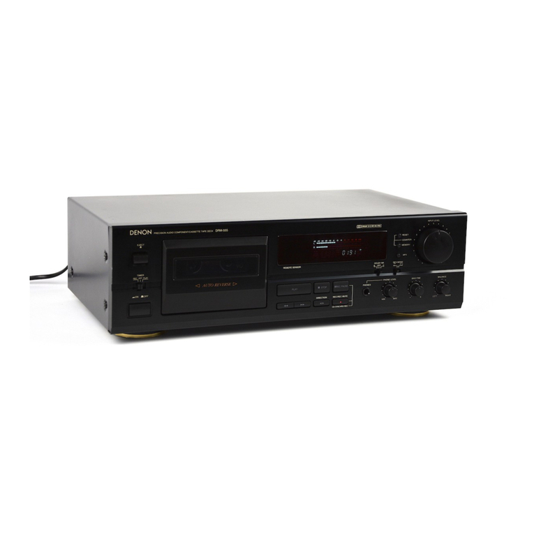
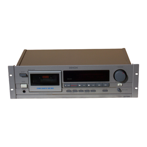
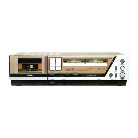
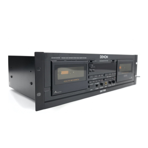
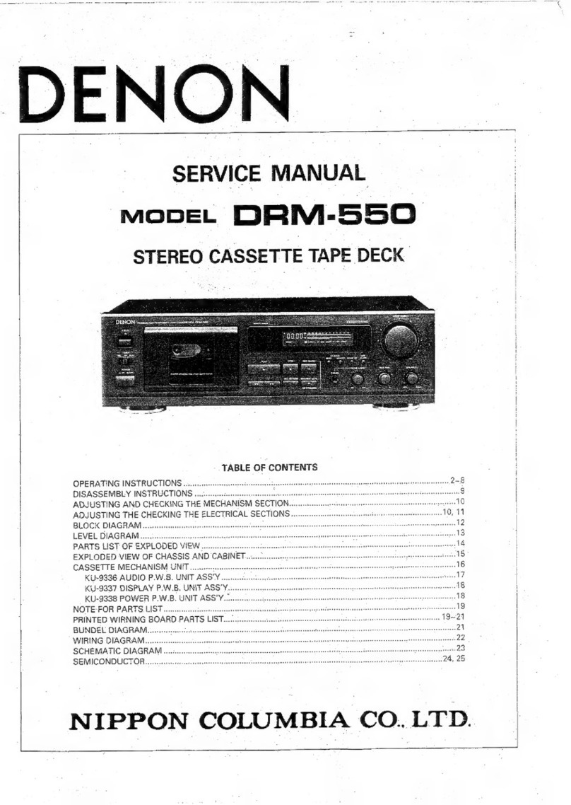
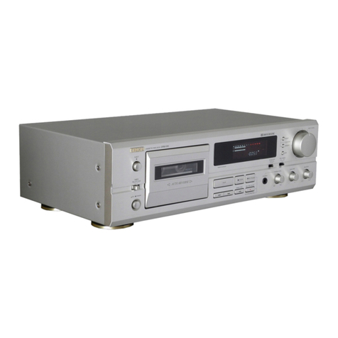
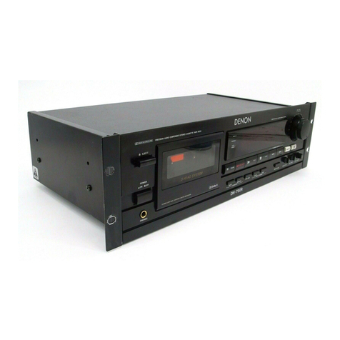
Denon DRW-5830 User manual

DENON
SERVICE
MANUAL
MODEL
DRW-5830
STEREO
CASSETTE
TAPE
DECK
31S
SDENON
bso
acesimeincacsic
oeow
ded
AUTO
REVERSE
aed
TABLE
OF
CONTENTS
KU-9322
AUDIO
P.W.B.
UNIT
ASS'Y
KU-9323
DISPLAY
P.W.B.
UNIT
ASS’Y
KU-9324
POWER
P.W.B.
UNIT
ASS'Y
NOTE
FOR
PARTS
LIST
.........cccesscssssecseecceasssscesesnecseeresscessorssees
PRINTED
WIRNING
BOARD
PARTS
LIST
BUNDEL
DIAGRAM
WIRING
DIAGRAM

IMPORTANT
TO
SAFETY
e
FOR
U.S.A.
&
CANADA
MODEL
ONLY
WARNING:
TO
PREVENT
FIRE
OR
SHOCK
HAZARD,
DO
NOT
EXPOSE
THIS
APPLIANCE
TO
RAIN
OR
MOISTURE.
CAUTION:
1.
Handle
the
power
supply
cord
carefully
Do
not
damago
or
deform
tho
power
supply
cord.
If
it
is
damagod
or
deformed,
it
may
cause
electric
shock
or
malfunction
when
used,
When
removing
it
from
wali
outlet,
be
sure
to
remove
by
holding
the
plug
attachment
and
not
by
pulling
the
cord.
2.
Do
not
open
the
top
cover
in
order
to
provant
olactric
shock.
do
not
apen
the
top
cover.
HW
problams
occur,
contact
your
OFNON
DEALER
3.
Do
not
place
anything
inside
Do
not
place
metal
odjocts
of
spill
quid
inside
the
cassette
tape
deck
Electris:
shock
of
malfunction
may
cosult
Please,
record
and
retain
the
Mode!
name
and
serial
number
af
your
sot
shown
on
tho
rating
label,
Model
No.
DRW-580
Serial
No,
—....—-
CAUTION
TO
PREVENT
ELECTRIC
SHOCK
DO
NOT
USE
THIS
(POLARIZED)
PLUG
WITH
AN
EXTENSION
CORD,
RECEPTACLE
OR
OTHER
OUTLET
UNLESS
THE
BLADES
CAN
BE
FULLY
INSERTED
TO
PREVENT
BLADE
EXPOSURE.
¢
POUR
LES
MODELES
AMERICAINS
ET
CANADIENS
UNIQUEMENT
ATTENTION
POUR
PREVENIR
LES
CHOCS
ELECTRIQUES
NE
PAS
UTILISER
CETTE
|
FICHE
POLARISEE
AVEC
UN
PROLONGATEUR
UNE
PRISE
DE
COU-
RANT
OU
UNE
AUTRE
SORTIE
DE
COURANT,
SAUF
SI
LES
LAMES
PEUVENT
ETRE
INSEREES
A
FOND
SANS
EN
LAISSER
AUCUNE
PARTIE
A
DECOUVERT.
RISK
OF
ELECTRIC
SHOCK
DONOT
OPEN!
CAUTION:
TO
REDUCE
THE
RISK
OF
ELECTRIC
SHOCK,
DO
NOT
REMOVE
COVER
(OR
BACK).
NO
USER
SERVICEABLE
PARTS
INSIDE.
REFER
SERVICING
TO
QUALIFIED
SERVICE
PERSONNEL.
The
lightning
flash
with
arrowhead
symbol!
within
an
equilateral
triangle
is
intended
to
alert
the
user
of
the
presence
of
uninsulated
“dangerous
voltage”
within
the
product's
enclosure
that
may
be
of
sufficient
Magnitude
to
constitute
a
tisk
of
olectric
shock
to
persons
>
The
exclamation
point
within
an
equilaterat
triangle
is
intended
10
alert
the
user
of
the
prosence
of
important
operating
and
maintenance
(servicing)
instruction
in
the
literature
accompanying
the ap-
pliance,
1,
Read
Instructions
—
All
the
safety
and
operating
12.
instructions
should
be
read
before
the
appliance
is
operated.
2.
Retain
instructions
-
The
safety
and
operating
instructions
should
be
retained
for
future
reference.
3.
Heed
Warnings
~
All
warnings
on
the
appliance
and
14,
in
the
operating
instructions
should
be
adhered
to.
4.
Follow
Instructions
~
All
operating
and
use
instruc-
15.
tions
should
be
fotlowed.
S.
Water
and
Moisture
-
The
appliance
should
not
be
16.
used
near
water
-
for
example,
near
a
bathtub,
washbowl,
kitchen
sink,
laundry
tub,
in
a
wet
basement,
or
near
a
swimming
pool,
and
the
like.
6.
Carts
and
Stands
-
The
appliance
should
be
used
only
with
a
cart
or
stand
that
is
recommended
by
the
manufacturer.
6A.
An
appliance
and
cart
combination
should
be
moved
with
care.
Quick
stops,
excessive
7
force,
and
uneven
=
:
surfaces
may
cause
Pa
the
appliance
and
cart
combination
to
overturn.
7.
Wail
or
Ceiling
Mounting
—
The
appliance
should
be
18.
mounted
to
a
wall
or
ceiling
only
as
recommended
by
the
manufacturer.
8.
Ventilation
-
The
appliance
should
be
situated
so
ts
that
its
location
or
position
does
not
interfere
with
its
proper
ventilation.
For
example,
the
appliance
should
not
be
situated
on
a
bed,
sofa,
rug,
or
similar
surface
that
may
block
the
ventilation
Openings;
or,
placed
in
a
built-in
installation,
such
as
a
bookcase
or
cabinet
that
may
impede
the
flow
of
air
through
the
ventilation
openings.
9.
Heat
-
The
appliance
should
be
situated
away
from
heat
sources
such
as
radiators,
heat
registers,
stoves,
or
other
appliances
(including
amplifiers)
that
produce
heat.
10.
Power
Sources
-
The
appliance
should
be
connected
20
to
a
power
supply
only
of
the
type
described
in
the
:
operating
instructions
or
as
marked
on
the
ap-
pliance.
11.
Grounding
or
Polarization
—
Precautions
should
be
taken
so
that
the
grounding
or
polarization
means
of
an
appliance
is
not
defeated.
FIG!
EXAMPLE
OF
ANTENNA
GROUNOING
AS
PER
NATIONAL
fTLECTRICAL
CODE
LAMINA
oan
rschiance
UNI?
fae
srt
m0
201
Shee
SECTION
sia
2
GROUWO
AMES
saeieaeeritangy
a
Fo
SAFETY
INSTRUCTIONS
Power-Cord
Protection
—
Power-supply
cords
should
be
routed
so
that
they
are
not
likely
to
be
walked
on
or
pinched
by
items
placed
upon
or
against
them,
paying
particular
attention
to
cords
at
plugs,
con-
venience
receptacles,
and
the
point
where
they
exit
from
the
appliance.
Cleaning
~
The
appliance
should
be
cleaned
only
as
recommended
by
the
manufacturer.
Power
Lines
-
An
outdoor
antenna
should
be
located
away
from
power
lines.
Outdoor
Antenna
Grounding
~
If
an
outside
antenna
is
connected
to
the
receiver,
be
sure
the
antenna
system
is
grounded
so
as
to
provide
some
protec-
tion
against
voltage
surges
and
built-up.
static
charges,
Article
810
of
the
National
Electrical
Code,
ANSI/NFPA
70,
provides
information
with
regard
to
proper
grounding
of
the
mast
and
supporting
struc:
ture,
grounding
of
the
lead-in
wire
to
an
antenna-
discharge
unit,
size
of
grounding
conductors,
loca-
tion
of
antenna-discharge
unit,
connection
to
grounding
electrodes,
and
requirements
for
the
grounding
electrode.
See
Figure
A.
Nonuse
Periods
—
The
power
cord
of
the
appliance
should
be
unplugged
from
the
outlet
when
left
unused
for
a
long
period
of
time.
Object
and
Liquid
Entry
—
Care
should
be
taken
so
that
objects
do
not
fall
and
liquids
are
not
spilled
into
the
enclosure
through
openings.
Damage
Requiring
Service
~
The
appliance
should
be
serviced
by
qualified
service
personne!
when:
A.
The
power-supply
cord
or
the
plug
has
been
damaged;
or
B.
Objects
have
fatten,
or
liquid
has
been
spilled
into
the
apptiance;
or
C.
The
appliance
has
been
exposed
to
rain;
of
D.
The
appliance
does
not
appear
to
operate
normal-
ly
or
exhibits
a
marked
change
in
performance;
or
E.
The
appliance
has
been
dropped,
or
the
enclosure
damaged.
Servicing
-
The
user
should
not
attempt
to
service
the
appliance
beyond
that
described
in
the
operating
instructions.
All
other
servicing
should
be
referred
to
qualified
service
personnel
O8S-MHY0
=

NOTE
ON
USE/OBSERVATIONS
RELATIVES
A
L'UTILISATION/NOTAS
SOBRE
EL
USO
Avoid
high
temperatures
Allow
for
sufficient
heat
dispersion
when
installed
on
a
rack.
Eviter
das
tampératuras
dlevéees
Tenir
compte
d'une
dispersion
de
chaleur
suffisante
lors
de
installa
tion
sur
une
étagére.
Evite
altas
temperaturas
Permite
la
suficiente
dispersion
del
calor
cuando
esté
instalado
en
la
consola.
Handle
the
power
cord
caretulty,
Hold
the
plug
when
unplugging
the
cord
Manipuler
le
cordon
d’alimentation
avec
précaution,
Tenis
la
prise
tors
du
débranche-
ment
du
cordon.
Maneje
et
cordén
de
energia
con
cuidado.
Sostenga
el
enchufe
cuando
de-
sconecte
el
cordén
de
energia.
@
Keep
the
set
free
from
moisture,
water,
and
dust.
@
Proteger
l’spparei!
contre
I’humidi-
té,
l'eau
et
la
poussidre.
e
Mantenga
el
equipo
libre
de
hume-
dad,
agua
y
polvo.
iy
@
Unplug
the
power
cord
when
not
using
the
set
for
jong
periods
of
time,
@
Débrancher
le
cordon
d‘alimenta-
tion
lorsque
l'appareil
n’est
pas
utilisé
pendant
de
longues
périodes.
«#
Desconecte
el
cordén
de
energia
cuando
no
utilice
el
equipo
por
mucho
tiempo.
Do
not
tot
foreign
objects
in
the
set.
Ne
pas
laisser
des
objets
étrangers
dans
l'appareil.
No
deje
objetos
extrahos
dentro
del
equipo.
-
Do
not
let
insecticides,
benzene,
and
thinner
come
in
contact
with
the
set.
Ne
pas
mettre
en
contact
des
insec-
ticides,
du
benzéne
et
un
diluant
avec
l'appareil.
No
permita
el
contacto
de
insectici-
das,
gasolina
y
diluyentes
con
el
|
"(For
sets
with
ventilation
holes}
«
Do
not
obstruct
the
ventilation
holes.
«
Ne
pas
obstruer
las
trous
d’aéra-
tion.
¢@
No
obstruya
los
orificios
de
ventita-
cién.
-
lg
Never
disassemble
or
modify
the
set
in
any
way.
Ne
jamais
démonter
ou
modifier
l'appareil
d'une
maniére
ou
d’une
autre.
Nunca
desarme
o
modifique
el
equipo
de
ninguna
manera.
o~
|
Thank
you
very
much
for
purchasing
the
DENON
component
stereo
cassette
tape
deck.
DENON
proudiy
presents
this
advanced
tape
deck
to
audiophiles
and
music
lovers
as
6
further
proof
of
OENON’s
non-compromising
pursuit
of
the
ultimate
in
sound
quatity.
The
high
quality
performance
and
easy
operation
are
certain
to
provide
you
with
many
hours
of
outstanding
listening
pleasure.
—
TABLE
OF
CONTENTS
—
Please
check
to
make
sure
the
following
items
are
included
with
the
main
unit
in
the
carton:
(1)
Operating
Instructions
......
"
1
{2}
Connection
Cords
.
{3}
Mini-Plug
Cable
..
FEATURES
®@
Computer
Controlled
Mechanism
Dual
Power
Supply
FEATURES
.
@
Dolby
HX-Pro
Headroom
Extension
System
CONNECTION
0.
:
M
Dolby
B
&
C
Noise
Reduction
Systems
NAMES
AND
FUNCTION
OF
PARTS
...
@
Manual
Bias
Adjustment
Control
CASSETTE
TAPES
.......
a
@
Dual
Computing
Tape
Counter
with
4-Digit
Readout
and
Memory
Stop
AUTOMATIC
TAPE
SELECTION
.
@
Music
Search
System
PLAYBACK
dese
WM
FL
Peak
Level
Meters
RELAY.
PUAY
aiscaz
pinecone
@
Auto
Tapo
Soloctor
MUSIC
SFARCIISYSTEM
@
=
2-Speed
Dubbing
AL
CORDING
wr
@
>
Rolay
Playback
PROPER
RECORDING
LEVEL
@
Synchronizod
Recording
HECORDING
BIAS
ADJUS
IMENT
.
siisgives
M@
Timer
Play
and
Timer
Recording
REC/REC
MUTE
AND
REC
PAUSE
BUTTON
.........
@
Optional
Remote
Controtlable
DIMMER
ADJUSTMENT
DUBBING
oo.
ecsceesseeeeeee
on
a
SYNCHRONIZED
RECORDING
FUNCTION
TAPE
COUNTER
AND
MEMORY
STOP
TIMER
RE
CORDING/
PLAYBACK
DOLBY
BAND
C
NOISE
REDUCTION
SYSTEM...
OOt
BY
HX-PRO
HEADROOM
EXTENSION
SYSTEM
MAINTENANCE
TROUULESHOO
TING
SPECILICATIONS
CONNECTION:
(ois
ee
—
osietet
Stee
ens
¢
Leave
your
entire
system
(including
this
cassette
deck)
turned
off
until
all
connections
between
the
deck
and
other
components
have
bern
completed,
Receiver
or
amplifier
@
Connecting
the
Deck
to
an
Amplifier
*
Before
connecting
the
deck
to
your
amplifier,
please
review
your
wWopbifior’s
instruction
manual,
¢
Use
the
while
plugs
for
the
loft
channel
and
red
piugs
for
the
right
channel.
@
Tape
Dubbing
*
Many
stereo
amplifiers
and
receivers
have
tape
dubbing
circuitry
so
that
tape
duplication
can
be
performed
between
two
or
more
tape
decks.
Review
your
amplifier’s
instruction
manual
for
a
full
explanation
of
this
mode
of
operation
@
Connecting
Headphones
To
tisten
through
headphones,
plug
your
headphones
into
the
PHONES
jack.
DRW-580
This
jack
is
for
the
synchro-
nized
recording
function
onty
Do
nat
plug
in
microphonas,
bradphonas
nae
other
plugs
Power
supply
outlet,
i
@
Installation
Precautions
If
the
deck
is
placed
near
an
amplifier,
TV
of
tuner,
noise
linduced
hum)
ot
baat
Interference
may
result,
especially
during
EM
of
AM
reception.
lf
this
occurs,
place
the
deck
further
away
from
other
components
or
reorient
its
position.
Caution
aaa
ies
A
mechanical
sound
is
heard
the
first
time
the
power
switch
is
set
to
"ON"
after
the
power
cord
is
plugged
into
an
outlet.
This
is
the
sound
of
the
cassette
mechanism
being
set
to
the
proper
operating
state,
and
is
normal.
(When
using
an
AC
outlet
on
a
receiver
or
amplifier,
used
an
“UNSWITCHED”
outlet.)
Ge
OSS
MYO

NAMES
AND
FUNCTIONS
OF
PARTS
®
AUTO
REVERSE
Hens
rr
rMne Rett
howe
WAR Foe
WaT
CVE
Power
Switch
(POWER)
Press
once
to
turn
the
power
to
deck
on,
and
once
more
to
turn
the
power
off.
The
deck
remains
ino
stand
by
(nan-operative)
mode
for
approx:
imately
2
seconds
after
it
is
switched
on
Eject
Button
(
&
)
Press
this
button
to
open
the
cassette
compartment
cover.
When
the
tape
is
running,
press
the
STOP
(
Ml)
button
first
to
stop
tape
transport,
then
press
the
Eject
button
Counter
Reset
Button
(COUNTER
RESET}
Press
this
button
to
reset
the
tape
counter
to
zero
MPX
Filter
Button
(MPX)
The
MPX
FILTER
button
should
be
used
to
prevent
interference
with
the
Dolby
NR
circuit
when
making
Dolby
NR
encoded
recordings
of
FM
stereo
programs.
Whon
making
Dolby
NR
encoded
recordings
from
any
program
sourco
other
than
FM
stereo,
wave
this
button
in
the
“OFF”
position,
Counter
Memory
Button
(MEMORY)
When
this
button
is
pressed
during
forward
tape
travel
{D),
fast
rewinding
{
44
)
will
stop
automatically
at
the
tape
counter
position
"0000"
Whan
this
button
is
pressed
during
reverse
tape
travel
(4),
fast
forwarding
(PP
}
will
slop
automatically
at
the
tape
counter
position
"0000",
Seo
page
13.
Dolby
NR
Switch
(DOLBY
NR)
To
record
of
playback
tapes
with
Dolby
8
or
C-type
noise
reduction,
set
this
switch
to
“B”
or
Turn
a
“OFF”
when
not
using
the
Dolby
N&
system,
Reverse
Mode
Switch
(REV.
MODE)
Select
the
typo
of
tape
transport
The
traverse
mode
canbe
set
to
fone
sido),
CLD
(continuous
playback),
RELAY
(ralay
playback),
Dubbing
Speed
Buttons
(OUBBING
SPEED)
Pressing
the
NORMAL
button
starts
regular
speed
dubbing
from
deck
A
to
deck
B.
Press
the
HIGH
button
to
perform
dubbing
at
double
speed.
See
page
1?
©
Bias Fine
Control
(BIAS
FINE)
(For
Normal,
CrO,
and
Metal
tape)
Use
this
control
to
fine-adjust
the
bias.
Standard
bias
is
obtained
at
the
centor
ctick-stop
position.
See
page
11
Input
Level
Control
(INPUT
LEVEL)
This
knob
adjusts
the
recording
input
level.
It
affects
the
level
in
both
channets.
See
page
10.
Cassette
Compartment
Cover
\f
the
cover
is
not
closed
completely,
the
tape
transport
buttons
will
remain
inoperative.
Headphone
Jack
(PHONES)
For
private
music
enjoyment
without
disturbing
others,
or
for
monitoring
a
recording,
a
headphone
set
may
be
connected
to
this
jack.
Use
a
headphone
with
an
impedance
rating
of
8
to
1200
Q/ohms.
Remote
Sensor
(REMOTE
SENSOR)
With
DRW-580
the
remote
contro!
unit
is
not
included.
Each
of
“PLAY,
FF,
REW,
STOP,
REC
PAUSE
and
REC/REC
MUTE”
functions
can
be
remote
controlled
with
wireless
handset
of
the
receiver
(DRA
Series
receivers).
For
details
refer
to
the
DRA
Series
operating
instructions
NOTE:
Note
that
only
the
A
deck
can
be
operated
with
remote
control
units
which
have
no
A/B
soloctor
button.
Caution:
=
eee
Whanavar
tha
powor
switch
is
in
the
OFF
state,
the
apparatus
is
still
connectad
on
AC
line
voltage.
Please
be
sure
to
unplug
the
cord
when
you
leave
home
for,
Say,
a
vacation.
Timer
Switch
(TIMER)
This
switch
is
provided
for
use
with
an
optional
audio
timer
tor
unattended
recording
of
morning-alarm
playback.
For
non-timer
operation,
this
switch
should
be
set
in
the
“OF!”
position.
See
page
14
®
Tape
Transport
Buttons
oy
=.
=
2
=
2
=
ee
rer
ee
[
PLAY
Play
Button
Press
to
playback
tape
i
a
Stop
Button
Press
to
stop
the
tape
in
any
mode.
ee
PS
me
ef
“4
Fort
Hesgand
thatine
Herter
dit
taed
teint
SS
ae
>
oe
Fuel
Fowwind
Guten
Haas
don
bit
darwin
e
Rec/Rec
Mute
Press
the
REC/REC
MUTE
(@)
button
and
PLAY
button
MUAANOO
UY
fo
shane
REC/REC
MUTE
Button
tding.
Wf
only
the
REC/REC
MUTE
(@)
button
is
Prossed,
the
deck
enters
the
(Deck
B
only)
Recording
Pause
mode.
Pressing
this
button
in
the
Recording
Pause
modi
wit
atart
Auto
Rec
Mute,
und
a
5-second
sitent
space
is
recorded
anto
the
lape.
See
page
1)
u
Ree
Pause
Button
Press
this
button
to
enter
the
recording
pause
mode
from
the
recording
of
recurding
REC
PAUSE
mute
mode.
This
button
can
only
be
used
during
recording.
See
page
11
{Deck
B
only}
4>
Direction
Button
Changes
the
tape
transport
direction
from
forward
"to
reverse
"@0.
and
vine
versa
(16)
Display
Incheators:
with
an
eneitcled
number
light
up
when
the
corresponding
bullon
is
pressed
Deck
A
Tape
Transport
indicators
Peak
Level
Meter
Indicates
the
recording
and
playback
siqnal
tevels
tor
the
det
and
cabht
channola
Dock
B
Tape
Cranspoet
lndicatars
dB]
-40 -30
-20/-10
-5
-3
-1
0
41
43
45
+
LOD
DOO
OAD
IMO
OOOO
ASSIS
8
[OOOO
OOOooOnooooOooOmoOOOAoD
db
HIGH:
Mpx
SYNC;
Deck
B
Memory
Indicator
—_—
[$$$
Deck
A
Tape
Counter
Deck
B
Tape
Counter
MPX
Filter
Indicator
Dubbing
Speed
Indicators
Remote
Control
Indicator
Deck
A
Memory
Indicator
Synchro
Rec
Indicator
Sea
pages
12,
13
CASSETTE
TAPES
ss
———
e
seemed
feta
bags
@
Handling
Precautions
B®
Storage
Precautions
©
©
120
Cassottes
¢
Do
not
store
cassette
tapes
in
a
place
where
they
wil
be
subject
to
C1270
«
ite
apes
are
not
tccommended
as
they
use
a
very
thin
tape
©
Extremely
high
temperature
or
excessive
moisturn
base
which
may
become
tangled
around
the
capstan
or
pinch
roller
«
Excessive
dust
e
Tape
Stack
«
Direct
suntight
Before
putting
a
tape
into
the
deck,
take
up
any
stack
wilh
a
pencil
oF
¢
Magnetic
fields
(near
TV
sets
or
speakers
your
finger
tip.
This
precaution
prevents
the
tape
from
becoming
*
To
eliminate
tape
slack,
store
your
cassettes
in
cassette
cases
with
hub
entangled
around
the
capstan
or
pinety
roller,
stops
@
Accidental
Erasure
Prevention
All
cassettes
havo
orasure
provention
tabs
for
each
side.
To
protect
valuable
recordings
trom
accidental
or
inadvertent
erasure,
remove
the
tab
for
the
appropriate
side
with
a
screwdriver
or
another
tool
é
¢
To
record
on
a
tape
whose
orasura
prevention
tabs
have bean
removed,
cover
the
tab
hotes
with
adhesive
tape
Erasure
prevention
tab
for
side
B

oe
teen
ees
me
ee
ep
AUTOMATIC
TAPE
SELECTION
.
SSascpcicdecet
te
This
Stereo
Cassette
Deck
contains
an
automatic
tape
selector
which
automatically
selects
the
optimum
bias
and
equalization
for
the
tape
in
use.
This
is
accomplished
by
detection
of
the
tape
type
detections
holes
in
the
cassette
housing.
PLAYBACK
ar
@
ff.
tape
without
tape
type
detection
holes
is
used,
the
deck
will
be
set
for
normal
tapes.
Detection
holes
for
metal
tape
Detection
holes
for
chrome
tape
The
operations
described
below
apply
to
deck
A
and
deck
B
alike.
Set
the
Tape
Monitor
switch
on
your
amplifier
or
receiver
to
the
TAPE
position.
The
numbers
in
the
Illustration
below
depict
the
order
in
which
operation
sieps
are
carried
out.
.
®
Switch
on
your
amplifier
or
receiver.
.
.
AUTO
REVERSE
Bla
@
Press
the
POWER
switch
to
the
ON
{
m=
)
position.
@
Press
the
EJECT
(
@
)
buttan
to
apen
the
cassette
compartment
cover.
@
Load
the
cassette
tape
and
close
the
cagsetta
compartment
cover.
@
Whan
dataning
to
a
tape
that
haa
bean
recorded
with
Dalby
nolse
reduction,
sat
the
DOLBY
NA
switch
to
match
the
system
used
at
the
me
of
recording.
DOLBY
NR
B
OFF
_C
-——
#4
Ca)
©
Press
the
Direction
{4}
button
to
select
the
direction
of
tape
transport.
Transport
Direction
indicator
Forward
Dd
Reverse
4
|
AUTO
REVERSE
>
a
wean
come
erste
@
Select
the
type
of
tape
transport
with
the
REVERSE
MODE
switch.
REV.MOODE
x
iz
ABLAY
To
flsten
to
one
side
only
Switch
position
To
listen
to
repeat
playback
of
both
sides
To
listen
to
continuous
play
back
of
both
sides
and
both
decks.
@
Press
the
PLAY
button
to
begin
playback.
@
Press
the
stop
{
MB}
button
to
stop
the
playback.
«
In
the
continuous
playback
mode
{REVERSE
MODE
set
toC=)},
playback
of
both
tape
sides
will
be
repeated
5
times
and
then
stop
automatically,
¢
Hf
different
types
of
Dolby
noise
reduction
are
used
for
record
and
playback,
playback
response
will
be
adversely
affected.
«©
When
power
is
turned
off
during
tape
transport,
it
may
not
be
possibie
to
remove
the
cassette
by
pressing
the
EJECT
(
4}
button.
In
this
case,
turn
on
power
again
before
you
press
the
EJECT
{
#)
button.
M@
RELAY
PLAY
(continuous
playback
of
the
tapes
In
deck
A
and
deck
B}
e
Load
a
cassette
Lape
into
dock
A
and
B,
and
set
the
Dolby
NR
bulton
correctly.
AUTO
REVERSE
OO
BAIT
AT
KAAX
AO
@
REVERSE
MODE
set
to
“RELAY”
@
Press
the
PLAY
button
of
the
deck
you
first
wish
to
listen
to.
©
To
stop
retay
play,
press
the
stop
{
M@)
button
of
the
deck
currently
playing
the
tape.
«
Relay
play
will
play
decks
A
and
8
in
succession
for
5
cycles,
upon
which
playback
stops.
When
playback
starts
from
deck
B,
when
switching
to
deck
A,
the
first
deck
A
playback
cycte
will
be
counted
as
the
second
cycle.
The
completion
of
§
cycles
will
always
be
at
the
opposite
side
of
the
tape
in
deck
B
MM
MUSIC
SEARCH
SYSTEM
the
music
search
system
detects
blank
sections
(lasting
for
at
least
4
seconds}
between
selections
in
order
to
locate
the
beginning
of
selections
in
the
forward
or
reverse
direction.
1.
To
advance
from
the
current
selection
to
the
beginning
of
the
next
selection
(CUE)
Press
the
PLAY
button,
keep
it
pressed
in,
and
press
the
Fast
Forward
(DP
)
button
when
the
tape
is
travelling
in
the
forward
{
D
}
direction.
Press
the
PLAY
button,
keep
it
pressed
in,
and
press
the
Rewind
(
44)
button
when
the
tape
is
travelling
in
the
reverse
(
4
}
direction
The
tape
transport
indicator
flashes,
the
deck
will
skip
the
rest
of
the
current
selection
and
automatically
resume
play
from
the
beginning
of
the
next
selection.
2.
To
repeat
playback
from
the
beginning
of
the
current
selection
(REVIEW):
Prons
the
PLAY
button,
koop
it
prossod
in,
and
press
the
Rewind
(
44}
button
when
the
tape
is
travelling
in
the
forward
{
>
}
direction.
Press
the
PLAY
button,
keep
it
pressed
in,
and
press
the
Fast
Forward
{
DP
)
button
when
the
tape
is
travelling
in
the
reverse
{
<
}
direction.
The
tape
transport
indicator
flashes.
The
deck
wil!
rewind
the
tape
to
the
beginning
of
the
current
selection
and
automatically
resume
play
from
that
point.
This
is
very
convenient
for
repeating
piayback
of
the
current
selection.
Notes
on
Musle
Search
Operation:
The
search
functions
operates
by
detecting
comparatively
long,
blank
sections
approximately
4
to
5
seconds
long,
in
between
recorded
selections.
Therefore,
the
system
may
not
operate
normally
in
the
following
cases:
¢
Recordings
with
discontinuous
speech
or
conversation
Recordings
with
long
periods
of
pianissimo
{softly
played
music)
Recordings
with
iong
silences.
Blank
sections
with
a
high
level
of
noise.
Blank
sections
shorter
than
4
seconds,
If
noise-emitting
appliances,
such
an
ploctric
racora,
dolls,
retageralors,
eic.,
are
operated
nearby.
@
REV
close
to
the
beginning
of
the
program
or
CUE
close
to
the
ending.
a)
0
<
Oi
00)
0

RECORDING
(DECK
B
only)
MB
PROPER
RECORDING
LEVEL
it
the
high
frequencies
{trabie
sounds)
aro
to
be
boosted,
tun
the
BIAS
A
too
high
recording
level
can
saturate
the
tape
and
cause
distortion.
FINE
controt
counter-clockwise
to
decrease
the
bias
current.
Turn
the
*
Switch
on
your
amplifier
or
receiver
and
the
source
component.
On
the
other
hand,
if
the
recording
level
is
set
too
low,
soft
passages
contro!
clockwisz
to
increase
bias
current.
will
be
marked
by
residual
noise.
A
proper
recording
evel
is
the
single
By
the
use
of
this
control,
you
can
record
tapes
with
a
frequency
®
Set the
Tape
Monitor
switch
on
your
amplifier
or
receiver
to
the
SOURCE
position.
4 :
most
important
factor
for
making
well
balanced
recordings.
response
that
will
perfectly
match
your
listening
taste.
Guideline
for
maximum
recording
level
TYPE
|
(Normal)
0
dB
level
on
peaks
3
Counterclockwise
TYPE
$1
(CrO2}
+1
dB
level
on
peaks
Z
_DENON
smeacr
sce
commen
cant
nts
one
DFW
80
TYPE
IV
(Metal)
+3
dB
level
on
peaks
4
een
CM
-_
:
=
=
>
Note;
Tho
opimum
recording
level
differs
deponding
on
the
program
E
Clockwise
O
A
O
source
and
the
typu
of
tape
used.
6
z
evcruseaon,
——
toh
Gee
ae
atest
sate
[4
FREQUENCY
(Hz)
AUTO
REVERSE
ciao
AUTO
REVERSE
ab
a>
Herren
cua
Wate
oy
aren
ou
rae
W@
RECORDING
BIAS
ADJUSTMENT
For
best
recording
results,
monitoring
during
recording
and
comparing
a
different
recordings
using
your
own
judgement
are
essential.
The
DENON
cassette
deck
is
equipped
with
a
BIAS
FINE
control
to
assist
you
in
setting
the
proper
bias
for
different
types
and
brands
of
lape.
Al
the
conter
stap-click
position,
the
deck
is
set
to
the
reference
REC/REC
MUTE
AND
REC
PAUSE
Button
To
record
a
S-second
blank
section
during
recording:
Press
the
REC/REC
MUTE
(@)
button.
A
5-second
blank
will
be
recorded
and
the
deck
will
enter
the
recording
standby
mode.
2.
To
record
a
$-second
blank
section
during
the
rocarding
standby
mode;
bias
level
for
Normal,
CrO,
and
Metal
tape,
If
the
resulting
recording
in
Press
the
REC/REC
MUTE
(@)
button
from
the
recording
standby
this
position
has
too
much
or
too
little
high
frequency
content,
mode.
A
5
second
blank
will
be
recorded
and
the
deck
will
enter
the
adjusting
tho
BIAS
FINE
contro}
can
be
useful
to
achieve
better
results.
recording
standby
mode
ayain.
3.
To
cancel
recording
of
blunk
space
Press
tho
REC
PAUSE
(I)
button,
Blank
space
recording
will
be
cancelled
and
the
deck
enters
the
recording
standby
mode.
@
Press
the
POWER
switch
to
the
ON
(
==
)
position.
Caution;
@
Load
the
cassette
tape.
©
8e
careful
not
to
erase
important
recordings
by
mistake.
Inadvertent
4,
To
extend
the
blank
section
with
another
5
seconds
or
more:
(Check
that
the
erasure
prevention
tabs
of
the
cassette
housing
have
start
of
recording
will
happen
in
the
following
cases:
Simply
press
the
REC/REC
MUTE
{@)
button
and
the
blank
section
will
not
been
broken
off.)
1.
Ifthe
PLAY
button
is
pressed
while
the
@
indicator
lights,
recording
be
increased
with
another
5
seconds
@®
Move
the
DOLBY
NR
switch
and
select
the
Dolby
NR
type
that
suits
the
starts.
recording
2.
lithe
PLAY
and
REC/REC
MUTE
(@)
button
are
pressed
at
the
same
DOLBY
NR
time,
recording
starts,
@
DIMMER
ADJUSTMENT
B_OFF_C
The
best
way
to
avoid
accidental
erasure
is
to
break
off
the
two
erasure
BIAS
FINE
With
the
ORW-580,
the
brightness
of
the
display
can
be
adjusted
in
seven
steps.
To
make
the
display
brighter,
press
the
B
deck's
fast
forward
(
DR
}
button
while
holding
in
the
B
deck’s
STOP
button.
To
make
the
display
dimmer,
press
the
fast
rewind
(
44}
button
while
prevention
tabs
on
the
cassette
housing.
@
ee
Direction
(€
>)
button
to
select
the
direction
of
tape
holding
in
the
STOP
button.
z
The
display
is
initially
set
to
the
maximum
brightness.
®
Select
the
type
of
tape
transport
with
the
REVERSE
MODE
switch,
prays:
¥
a
Mode
Switch
position
To
record
on
onty
one
side
os
To
continuously
record
on
both
sides
Cl
or
RELAY
©
Press
the
REC/REC
MUTE
(
@}
button
to
set
the
recording
pause
mode,
The
@W
indicator
will
light
up.
@
Adjust
the
recording
level
with
the
INPUT
LEVEL
control
while
watching
the
Peak
Level
Meter
@®
Press
the
PLAY
button
to
start
the
recording,
The
PLAY
(<4
or
PD)
and
the
@
indicator
will
tight
during
recording.
@®
To
stop
recording,
press
the
stop
{
HH)
button.
€9
To
pause
the
recording,
press
the
REC
PAUSE
(II)
button.
Press
the
PLAY
button
to
resume
recording.
a
11
S26
a
I
a
O8sc-MHO
Bia

DUBBING
(from
deck
A
to
deck
B)
*
Switch
on
the
amplifier
or
receiver
e@
Set the
Tape
Monitor
switch
on
your
amplifier
or
receiver
to
the
TAPE
position.
DENON
wean
wee
of
AUTO
REVERSE
AUTO
REVERSE
van
are
CORRE
reTTAE
@
Press
the
POWER
switch
to
the
ON
(
am)
position,
@®
Load
the
cassette
tape
to
be
played
in
deck
A
and
the
one
to
be
recorded
in
deck
B
@
Selact
the
type
of
tape
transport
with
the
REVERSE
MODE
switch,
REV.MODE
x
CSD
RELAY
Reverse
mode
Operation
Dubbing
is
performed
only
for
one
side.
ta
The
decks
stop
when
either
deck
A
or
B
reaches
the
end
of
the
tape,
The
tape
direction
is
reversed
on
each
CD
deck
when
they
reach
the
end
of
the
tape.
(This
is
convenient
for
dubbing
to
a
tape
with
a
different
length.)
Durning
dubbing
of
(he
side
facing
you,
the
deck
that
first
reaches
the
end
of
the
tape
will
stand
by
until
the
other
deck
reaches
the
end
of
the
tape,
then
both
decks
will
reverse
the
tape
direction
together.
(Depending
on
the
manufacturer,
the
length
of
tapes
having
the
same
recording
time
may
differ
somewhal.
Setting
this
mode
permits
the
arrange-
ment
of
the
beginning
portion
of
the
opposite
side
Of
the
taped
SYNCHRONIZED
RECORDING
FUNCTION
—
-_—
@
Convenient
synchronized
recording
can
be
performed
when
used
in
combination
with
a
DENON
CD
player
equipped
for
the
synchronized
recording
function
@
SYNCHRO
Jack
Connection
Connect
the
SYNCHRO
Jack
with
a
DENON
CD
player
which
is
equipped
with
a
SYNCHRO
jack,
then
make
a
synchronized
recording.
Use
the
connection
cord
supplied
with
this
cassette
deck
@
Switch
on
your
amplitier
or
receiver
and
the
CD
player,
»
Set
the
tape
Monitor
switch
on
your
amplifier
or
receiver
to
the
source
position
42
@
to
bayin
normal
speed
dubbing,
pross
the
OURBING
SPELD
NOKMAL
button,
The
DUB
indicator
will
tight
at
thts
time.
To
high
speed
dubbing,
press
the
DUBBING
SPEED
HIGH
button
The
HIGH
indiculdr
will
fight
at
this
time
®
To
stop
dubbing,
ipress
the
stop
(MB)
button
of
deck
A
or
dock
B
©
When
dock
A
is
in
the
playback
mode
and
deck
B
is
in
the
stop
condition,
setting
deck
B
fe
the
recording
pause
mode
will
engage
the
normal
spoad
dubbing
pause
mode.
Oubbing
is
then
startud
by
pressing
the
PLAY
button.
e
Whon
dubbing,
the
rocording
level
and
the
Dolby
NA
recording
will
be
tha
same
as
those
of
the
playback
tape,
regardless
of
the
positions
of
the
INPUT
LEVEL
control
and
the
DOLBY
NR
button:
©
When
sistuning
to
the
playback
sound
during
normal
spood
dubbing,
the
DOLBY
NR
switch
remains
off
even
if
it
is
pressed.
®
The
playback
sound
cannot
be
heard
during
high
speed
dubbing.
e
Operation
using
the
REC/REC
MUTE
(
@)
and
REC
PAUSE
(If)
buttons
of
deck
B
is
permitted
during
normal
speed
dubbing.
*
Buttons
other
than
the
stop
(MB)
button
cannot
be
used
during
high
spoed
dubbing
CD
Player
”
DENON
meee
ano
carvan
som
users
ice
DRW-400
CLHODLAY
1G
A
HX
AAO)
AUTO
REVERSE
Me
aruorcanenes
srt
@
Load
the
tape
anto
which
you
want
to
record
into
deck
B,
the
disc
you
want
to
recard
into
the
CD
ployer,
(2
Following
the
recotding
ingtuctions
en
page
10,
set
the
Dolby
NR
wmode,
the
digetos,
the
reverse
mode
and
the
mput
level.
@
Set
the
CO
player
to
the
stop
or
pause
mode.
@rr
the
AEC/REC
MUTE
(@)
button
and
REC
PAUSE
(I)
button
or
ty.
The
casuotte
deck
and
CD
player
ure
aulomatically
wat
to
the
synchronized
recording
mode.
The
“SYNC”
indicator
lights
on
the
cassette
deck
and
the
synchronized
recording
mode
is
indicated
on
the
CO
player.
(for
details,
rofer
to
the
CD
player's
operating
instructions.)
@
Jo
slop
synchronized
recording,
press
the
stop
button
on
deck
B
and
slop
button
oo
CD.
Tha
synchronized
recording
mode
is
cancelled
tor
both
the
cassette
deck
and
CD
player.
©
To
stop
synchronized
recording
temporarily,
press
the
stop
button
on
the
CD
player,
A
5-second
blank
space
is
created
on
the
tape,
after
which
Ihe
recording
pause
mode
is
set.
Tho
"SYNC"
indicator
flashes.
To
rosume
synchronized
recording,
preas
the
PLAY
button
on
the
CD
player
TAPE
COUNTER
AND
MEMORY
STOP
COUNTER
RESET
wow
|
8888
HIGH
ous
SYNC
6886
38
Note:
©
if
synchronized
recording
1s
slartad
when
the
CO
playar
isin
a
mode
uther
than
the
stop
or
pause
wmode
or
when
no
chase
ty
pet,
thu
SYNC"
tockcator
on
the
cassatie
deck
Hashes
apd
Ue
recording
padise
Mode
is
set
until
synchronized
recording
is
possibly
on
the
CO
player
e
In
the
synchronized
recording
mode,
only
the
STOP
button
on
deck
B
will
function
Caution:
¢
Do
not
set
the
cassette
deck
to
the
synchronized
recording
mode
when
the
CD
player
is
in
the
play
modu.
Also,
do
not
turn
off
the
power
of
the
cassutte
deck
or
the
CD
player
during
synchronized
recording.
Doing
so
can
result
in
malfunction
¢
During
the
editing
operation,
when
using
the
uditng
functions
oo
the
CD
player,
bo
sure
to
select
a
tape
with
@
sufficiantly
long
recording
time.
For the
CD
player's
editing
functions,
refer
to
the
CO
player's
operating
instructions.
COUNTER
RESET
MEMORY
REC
PAUSE
Parte
Dele
in]
RECTION
RECAEC
MUTE
1)
Operation
of
the
Tape
Counter
{1)
Press
the
RESET
button
to
reset
the
counter
to
“9000”,
(7)
By
using
the
PLAY,
FF,
or
REW
functions,
the
reading
of
the
counter
will
change
to
indicate
index
position.
*
During
recording
and
playback
operations,
the
counter
is
useful
for
noting
the
location
of
existing
programs
or
positions
where
recording
is
to
be
started,
e
The
reading
of
this
counter
does
not
correspond
with
that
of
any
other
deck.
{3)
deck
A
and
deck
B
have
the
memory
of
their
own
counter,
2}
MEMORY
STOP
Operation
(1)
During
recording
or
playback,
the
Memory
Stop
feature
can
be
used
to
locate
a
particutar
point
on
the
tape.
Press
the
COUNTER
RESET
button
at
the
desired
point,
(2)
Then
Press
the
COUNTER
MEMORY
button,
the
MEMO
indicator
lights.
(3)
When
the
Rewind
{
#4
}
button
is
pressed
during
forward
tape
travel
(D>),
or
the
Fast
Forward
(
DP
)
button
is
pressed
during
reverse
tapo
travel
(<J),
the
tape
is
rapidly
rewound
(or
advanced)
unt!
the
counter
indication
of
"0000"
is
reached.
©
The
Memory
Stop
feature
will
rewind
or
forward
the
tape
to
within
-5
counts
in
the
forward
())
direction
{from
"0900"
tg
"-9925")
and
to
within
+6
counts
in
the
reverse
{1}
direction
(from
“9000”
to
"0005"),
Alter
this,
suveras
seconds
are
required
for
corrective
operations.
*
The
Memory
Stop
function
operates
indepundentiy
in
both
direc-
tions
for
deck
A
and
deck
8
Caution:
if
the
memory
stop
operation
is
performed
after
repeated
fast-
forwarding
or
rewinding,
the
tape
may
not
stop
at
the
proper
position,
13

i
;
4
4
2
4
TIMER
RECORDING/PLAYBACK
—_......
Timer
recording/playback
can
be
made
using
any
audio
timer
available
on
the
market,
Amplifier
DRW.
580
Wall
outlet
On
timer
cacording/
playback
@
Timer
recording
procedure
Fun
eon
ae
14
Mako
sure
the
connections
are
correct,
especialty
tho
power
supply
connections,
Turn
“on”
the
power
switch
of
each
appliance.
Tune
the
desired
station
on
tha
tuner
Load
the
tape
for
tacording,
(Miler
nur
the
arose
pravention
tab
in
not
broken
off;
if
it
is,
cover
the
tule
with
plastic
tape).
Set
the
Dotby
NR
switch
to
the
appropriate
position
.
Make
sure
the
monitor
switch
to
tho
SOURCE
position
Adjust
the
recording
input
level
Set
the
starting
position
of
the
tape
Set
tho
timer
switch
(TIMER)
lo
the
"REC"
sida
TIMER
REC
OFF
PLAY
—
10,
Set
the
audio
timer
to
the
dasired
time.
The
audio
timer
wilt
turn
the
power
supply
on
at
the
desired
time.
*
With
the
above
procedures,
timer
controlled
recording
can
be
made.
When
the
preset
time
comes,
the
power
is
supplied
and
the
FM
broadcast
can
be
recorded,
DOLBY
B
AND
C
NOISE
REDUCTION
SYSTEM
Speaker
System
@
Timer
playback
procedure
er
sen
Make
sure
the
connections
aro
correct,
espocially
the
power
supply
connections.
Turn
“on”
the
power
switch
of
each
appliance.
Load
the
pre-recorded
taps
to
be
played
back,
Sot
the
Dolby
NA
switchas
to
the
appropriate
poaitions.
Set
the
monitog
switch
of
the
Amplifier
to
the
TAPE
position.
Press
the
PLAY
{
b
)
button
and
playback
the
tape;
adjust
the
playback
tevel.
Pross
the
stop
(M)
button.
Set the
timer
switch
(TIMER)
to
the
“PLAY”
sido.
TIMER
REC OFF
PLAY
8.
Set the
audio
timer
to
the
desired
time.
The
audio
timer
will
turn
the
power
supply
on
at
the
desired
time.
*
With
the
above
procedures,
timer
playback
can
be
accomplished.
When
the
preset
time
comes,
the
power
is
supptled
and
playback
will
start.
Note:
©
Please
read
the
operating
instructions
for
the
timer
before
use.
¢
if
the
timer
recording
or
playback
is
not
desired,
be
sure
to
switch
the
timer
awitch
(TIMER)
to
“OFF".
«
When
using
timers
that
allow
several
“on/off”
Operations,
timer
start
functioning
can
continue
an
unlimited
numbor
of
times
until
the
tape
in
the
machine
is
finished.
@
The
Dolby
noise
reduction
system
substantially
reduces
the
tape
background
noise
(hiss)
inherent
in
the
cassette
medium.
Dolby
B
NR
is
most
widely
in
use.
However
Dolby
C
NR
is
a
much
more
recent
devalopment
and
represents
significant
improvements
over
Dolby
B
NR
Tape
background
noise
consists
primadly
of
high
frequency
informa:
(ton,
which
is
particularly
annoying
during
soft
passages.
The
Dolby
NR
system
increases
the
level
of
low
volume
mid-
and
high-frequency
signals
during
recording
and
reduces
the
level
of
these
signals
by
an
identical
amount
during
playback.
As
a result,
the
playback
signal
is
identical
to
the
origina!
source,
but
the
level
of
background
noise
generated
by
the
tape
is
greatly
reduced.
WM
The
operating
principle
of
Dolby
C
NR
is
simitar
to
that
of
Dolby
B
NR
except
for
the
encoding/decoding
response
curves.
The
noise
reduc
tion
effect
obtained
with
Dolby
C
NR
is
up
to
20
dB,
compared
to
10
d@
with
Dolby
B
NR.
In
addition,
Dolby
C
NR
uses
an
anti-saturation
network
and
spectral
skewing
circuitry
for
a
significant
improvement
in
the
dynamic
range
of
the
mid.
to
high
frequoncion.
DOLBY
HX-PRO
HEADROOM
EXTENSION
SYSTEM
This
deck
is
equipped
with
the
Dolby
HX-PRO
headroom
extension
system
Since
the
system
functions
automatically
during
recording,
no
switching
operation
or
adjustment
is
required.
The
system
is
effective
with
any
type
of
Normal,
CrO,
and
Meta
tape.
The
Dolby
HX-PRO
headroom
extension
system
functions
during
recording
fo
raise
the
saturation
tevel
in
the
treble
range.
Therefore,
most
of
the
treble
range
components
distoried
or
lost
during
recording
on
convention
al
cassette
decks
are
more
faithfully
recorded
on
the
new
DENON
cassette
deck
MAINTENANCE
soy
ses
:
@
Head
Cleaning
After
long
usage,
tape
coating
or
dust
may
adhere
to
the
heads,
causing
deterioration
of
sound,
Therefore,
the
parts
depicted
in
the
illustration
should
be
cleanod
regutarly.
Use
a
cotton
swab
moistened
with
a
tape
head
cleaning
solution
(such
as
alcohol)
Note:
1,
Some
cloaning
cassettes
on
the
market
have
strong
abrasive
offocts
and
may
scratch
the
hoards.
Always
use
colton
swabs
instead
of
cleaning
cassettes.
2.
Sinco
the
use
of
metal
tape
is
apt
to
collect
mora
dust
on
the
heads,
the
heads
should
be
cleaned
more
often
to
anjoy
the
bost
possible
sound.
Features
of
the
Dolby
HX-PRO
Headroom
Extension
System
(1)
Performance
of
Normal
and
CrO;
tapes
can
be
improved
to
very
close
of
that
offered
by
Metal
tape.
(2)
The
dynamics
in
the
treble
range
are
improved
signifteantly.
{3}
Since
no
decoding
is
necessary
during
playback,
the
improved
sound
can
be
enjoyed
on
any
type
of
tape
deck,
including
portable
players
and
car
audio
systems.
(4)
The
system
functions
whother
the
Dolby
B/C
NK
systeny
is
engagad
or
not.
@
Cleaning
the
Pinch
Rollers
and
Capstans
If
the
pinch
rollers
or
capstans
accumulate
dust,
tape
Uransport
may
become
unstable,
as
a
result
from
slippage,
during
tcording
ot
Playback.
Tho
tape
can
also
be
damaged
if
it
gets
entangled
in
the
capstan.
Clean
these
parts
with
a
cotton
swab
or
a
tape
haad
cleaning
solution
(such
as
a:
M@
Demagnetizing
the
Heads
The
heads
will
become
magnetized
after
long
usage
or
it
strongly
magnotized
abjects
are
brought
naar
them.
The
result
isa
generation
of
noise,
loss
of
tho
high
frequency
range,
and
in
axtrame
cases
erasure
of
trobie
componenta
on
pre-recorded
tapes
ie
combination
with
added
noise.
Thus,
the
heads
should
be
demagnetized
at
regular
intervals.
(Head
domagnetizers
are
separately
available
from
your
dealer.)
@
How
to
Demagnetize
the
Tape
Heads
1,
Turn
off
the
power.
2.
Turn
on
the
demagnetizer
while
it
is
at
Ieast
30
cm
away
from
the
heads.
Bring
the
damagnetizer
near
the
hoads
and
slowly
move
it
in
small
circles
four
or
five
times
in
front
of
each
head,
making
sure
you
do
not
touch
them.
3.
Slowly
move
the
demagnetizer
away
and
turn
it
off
whnn
itis
at
Joast
30
cm
away
from
the
heads,
off
cloth
moistened
with
a
Hol)
15
O8S-Mya
a

TROUBLESHOOTING
..
..
——
Check
the
foflowing
before
you
draw
the
conclusion
that
your
Stereo
Cassette
Deck
is
malfunctioning.
1.
Are
all
the
connections
correct?
2.
Are
all
system
components
being
operated
correctly
in
accordance
with
the
operating
instructions?
3.
Are
the
speakers
and
amplifier/receiver
functioning
correctly?
if
the
tape
deck
still
does
not
function
properly,
check
the
symptom
against
the
list
below.
If
the
symptom
does
not
correspond
to
the
check
list,
please
contact
your
DENON
dealer.
Seeds
seins
Problem
Cause
Remedy
Tape
does
not
run
«
Power
cord
is
disconnected.
@
Check
power
cord.
«
Tape
is
loose.
e
Tighten
tape
with
a
pencil,
etc.
e®
Cassette
is
not
toaded
properly.
e@
Load
cassette
properly.
«
Defective
cassette.
®
Replace
cassette.
Tape
is
not
recorded
when
REC/REC
MUTE
(@}
e
No
cassette
is
loaded.
@
Load
cassette.
button
is
pressed
e
Erase
prevention
tabs
are
broken
off.
e
Cover
holes
with
adhesive
tape.
Sound
is
warbled
and
distorted.
«
Heads,
capstan
or
pinch
roller
ara
dirty.
e
Clean
them.
@
Tape
is
wound
too
tight
@
Fast
forward
of
rewind
to
jioosen
tape
winding.
e
Recording
input
level
is
too high.
e
Adjust
recording
input
levet.
e
Tape
is
worn
out
and
has
“drop-outs”.
e
Replace
tape.
Excessive
noise
e
Tape
is
worn.
e@
Roplace
them,
@
Heads,
capstan
or
pinch
roller
are
dirty.
e
Cloan
them
e
Heads
ara
magnetized.
e
Demagnetize
heads.
*@
Recording
input
level
is
too
tow.
e
Adjust
recording
input
level.
High
frequency
range
(treble)
is
emphasized.
Dolby
NR
switch
is
set
improperly.
Set
Dolby
NR
Switch
properly.
High
frequency
range
(treble)
is
lost.
Heads
are
dirty.
Tape
is
worn.
Clean
them.
Replace
tape.
The
cassette
tape
cannot
be
removed
L..
.
See
ew,
igh
eee
If
the
POWER
switch
is
turned
off
either
during
recording
or
playback
and
the
unit
is
stopped,
there
may
be
cases
when
the
cassette
cannot
be
removed,
even
if
the
EJECT
(
&
}
button
is
pressed
Turn
the
POWER
switch
ON
(=)
again,
and
then
press
the
STOP
{
MM}
button.
Now,
press
the
EJECT
{
&
|
button
to
remove
the
cassette
tape.
SPECIFICATIONS
—__
Type
Vertical
tape
loading;
4-track
2-channel
Input
stereo
dorible
cassette
dock
UNE
Heads
Play
back
head
x
1
recording/playback
head
x
1
Erase
head
(Double-gap
ferrite}
x
1
Output
Motors
DC
servo
motor
x
2
LINE
Tape
Speed
4.8
cm/sec.
Fast
Forward,
Rewind
Time
Approx.
100
sec.
with
a
C-60
cassette
PHONES
Recording
Bias
Approx
106
kHz
Overall
S/N
Ratio
{at
3%
THD
levet)
Dolby
C
NR
on;
more
than
74
dB
(CCIR/ARM)
Power
Supply
Overall
Frequency
Power
Consumption
Response
20
-
17,000
Hz
+3 dB
(at
~20
dB,
Metal
tapo)
Dimensions
Channel
Seperation
Wow
&
Flutter
Moro
than
40
dB
{at
1
kHz)
0.08%
WAMS,
+0.14%
w.
peak
Weight
80
mV
{~20
dBm)
Input
fevel
at
maximum
Input
impedance:
50
kQ/kohms
unbalanced
775
mV
(0
dB)
output
fevel
at
maximum
{with
47
kQ/kohms
load,
recorded
level
of
200
pwb/mm)
1,2
mW
output
level
at
maximum
{optimum
load
impedance
8
Q/ohms
~
1.2kQ/kobms)
60
Hz,
voltage
is
shown
on
rating
tabel
16W
434
(W)
x
136
(H}
x
263
(0}
mm
{17-3/32"
x
0-00/00"
x
00-00/00"}
4.0
kg
(00
Ibs)
*
Above
specifications
and
design
are
subject
to
change
without
prior
notice.
Best
results
will
bo
obtained
with
use
of
DENON
GR
Series
cassetie
topes.
Dolby
noise
reduction
and
HX
Pro
headroom
extension
manufactured
under
ficense
from
Dolby
Laboratories
Licensing
Corporation.
HX
Pro
originated
by
Bang
&
Olufsen.
“DOLBY”,
the
doubie-D
symbol
0G
and
“HX
PRO”
are
trademarks
of
Dolby
Laboratories
Licensing
Corporation.
AB

ees
ORW-S80
(1)
(2)
(3)
(4)
(5)
(6)
DISASSEMBLY
INSTRUCTIONS
How
to
Remove
the
Front
PANEL
A'ssy
Remove
the
six
screws
(SPECIAL
SCREW)
(101)
in
the
side
of
the
top
cover
(35).
Move
the
top
cover
to
the
rear
and
rise
it
to
remove
it.
Disconnect
all
lead
connectors.
C.
Mecha
(A)
_—_—P.B.
Head
wire
~
CB131 Audio
P.W.
board
C.
Mecha
(B)
{
ERASE
Head
wire
—-
CB143
Power
P.W.
board
PB/REC
Head
wire
—-
CB141
Audio
PW.
board
Display
CW121-1A
—
CN121-2A
P.W.
board
|
CW121-1B
—
CN121-2B
Remove
the
Volume
knob
(26).
Remove
the
screw
(3X8CBTS(P)-B)
(103).
Remove
the
screw
(3X8CBTS(S)-B)
(102).
Remove
the
two
Hooks
on
the
bottom,
Front
Panel
Ass’y
can
be
|
Audio
P.W.
board
removed
towards
the
front.
2.
3hooks
on
the
bottom
ot
rear
panel
How
to
Remove
the
Cassette
Mechanisms
Remove
the
four
mechanism
retaining
screws
(3X8CBTS(P)-B)
(103),
(3X8CBTS(S)-B)
(102)
and
take
out
C.
Mechanism
(A)
(22)
and
C.
Mechanism
(B)
(23).
3.
(1)
(2)
How
to
Remove
the
Display
P.W.
board
Disconnect
leads
connectors.
C.
Mecha
(A)
—
CN242
C.
Mecha
(B)
—
CN241
Remove
the
six
Display
P.W.
board
tetaining
screws
(3X8CBTS(P)-B)
(103)
and
take
out
the
Display
P.W.
board.
Display
P.W.
board
How
to
Remove
the
Cassette
Door
Remove
the
Mini
Damper
(11)
retaining
screw
(3X8CBTS(P)-B)
(103)
and
take
out
the
Mini
Damper
(11).
Hold
the
legs
of
the
CASSETTE
BOX
folded
inwards
and
pull
up
to
remove
the
CASSETTE
BOX
(13)
and
BOX
SPRING
(15)
(16).
Front
surface
of
front
ass'y

i
i
ng
ee
Ne
ee
5.
How
to
Remove
the
Back
panel
(1)
Remove
the
top
cover
(35)
and
front
Panel.
Ass’y.
(Refer
to
section
1.)
(2)
Remove
the
screw
(3X8CBTS(P)-B)
(103)
that
is
holding
the
4P
pin
jack.
(3)
Remove
the
busing
(6)
(7)
that
is
fixing
power
supply
cord
from
back
panel
(48).
(4)
Remove
the
three
hooks
on
the
bottom
of
back
panel
(48)
and
pull
the
unit
back
to
detach
it.
6.
How
to
Remove
the
Audio
P.W.
Board
(1)
Remove
the
top
cover
(35)
and
the
front
esc.
Ass’y.
(Refer
to
section
1.)
(2)
Remove
the
screw
(3X8CBTS(P)-B)
(103)
that
is
holding
the
4P
pin
jack.
(3)
Remove
the
connectors
from
the
audio
P.W.
board
and
power
P.W.
board.
power
P.W.
board
CW191
—
CN191
audio
P.W.
board
(4)
Remove
the
five
screws
(3X8CBTS(P)-B)
(103),
(3X8CBTS(S)-B)
(102)
the
audio
P.W.
board
can
be
removed
by
rising
it.
7.
How
to
Remove
the
Power
Supply
P.W.
board
{1)
Remove
the
top
cover
(35).
(Refer
to
section
1.)
(2)
Remove
the
busing
(6)
(7)
that
is
fixing
power
supply
cord
from
rear
panel
(48).
(3}
Remove
the
connectors
from
the
audio
P.W.
board
and
power
P.W.
board.
power
P.W.
board
CW191
—~
CN191
Audio
P.W.
board
(4)
Remove
the
seven
screws
(4X10CBST({P)-Z)
(104),
(3X8CBST(P)-B)
(103)
that
are
holding
the
power
transformer
and
P.W.
board.
The
power
supply
PW.
board
can
be
removed
by
rising
it.

‘amare
DRW-580
ey
ADJUSTING
AND
CHECKING
THE
MECHANISM
SECTION
1.
Replacing
the
Pinch
Roller
Before
replacing
the
pinch
roller,
Clean
the
tape
contact
surface
of
the
pinch
roller
and
the
capstan
shaft.
Most
causes
of
Poor
tape
transport
can
be
traced
to
dirty
pinch
roller
and
Capstan
shaft
Remove
the
clips
that
press
the
Pinch
roller
and
pull
the
pinch
roller
forward
to
remove
it.
After
replacing,
run
a
padless
C-90
tape
to
check
for
tape
curls
at
the
tape
guide
section
of
the
head.
2.
Checking
the
Pressure
Force
of
the
Pinch
Roller
In
the
playback
mode,
hook
a
spring
weight
onto
the
bracket
at
the
center
of
the
pinch
roller.
After
Separating
the
pinch
roller
from
the
Capstan
shaft,
allow
the
pinch
roller
to
contact
the
caps-
tan
shaft
again.
Check
to
make
sure
the
Spring
weight
reads
be-
tween
250
~350
g
when
the
pinch
roller
Starts
to
rotate.
Replace
the
pinch
roller
when
it
does
not
conform
to
the
standard
Specification
values.
Capstan
shaft
|
a
'
7
!
ligt—
250~
350g
it
3.
Replacing
the
Record/Playback
Head
{1)
How
toremove
the
R/P
HEAD.
1)
Remove
Securing
screw
and
azimuth
adjusting
screw
-
from
the
record/playback
head.
2)
Remove
the
soldered
head
wire
and
disassemble
the
mechanical
unit
to
remove
the
record/playback
head.
(2)
How
to
assemble
the
R/P
HEAD.
Reverse
the
above
(1)
procedures
for
removing
the
R/P
HEAD.
”
Solder
the
HEAD
WIRE
according
to
the
diagram.
mechanism
(recording/playback
head)
4.
Checking
the
Take-up
Torque
Load
the
Cassette
type
torque
meter
(SONY
TW2114).
Check
to
make
Sure
that
the
average
torque
meter
reading
is
Within
30-70
g-cm
during
playback.
10
-—_—_———
5.
Checking
the
FF
and
REW
Torques
Load
the
cassette
type
torque
meter
(SONY
TW2231).
Check
to
make
sure
the
torque
meter
indicates
within
80~170
g-cm
at
the
end
of
FF
and
REW.
6.
Checking
the
Back
Tension
Torque
During
Record/Playback
Load
the
cassette
type
torque
meter
(SONY
Tw21
11);
check
to
make
sure
the
torque
meter
reads
between
2
~—6
g-cm
during
Playback
and
that
there
is
no
unevenness.
If
it
is
not
within
this
range,
replace
the
reel
ass‘y
or
Washer.
7.
Checking
the
FF
and
REW
Times
Load
a
C-60
Cassette
tape
(DENON
GR-2/60):
check
to
make
sure
the
tape
is
fast
forwarded
or
rewound
within
120
seconds.
If
it
is
not
within
this
range,
check
sections
5
and
6.
8.
Checking
the
Existence
of
a
Cassette
Housing
and
the
Operation
of
the
Erase
Prevention,
Metal
and
Chrome
Switch
Confirm
that
the
sensor
arm
Properly
detecting
the
tape
type
de-
tection
holes
on
the
cassette
housing.

ADJUSTING
THE
ELECTRICAL
SECTIONS
e@
Measuring
instruments
necessary
for
adjust-
ments
(1)
Audio
signal
generator
(2)
Variable
resistance
attenuator
(3)
Electronic
voltmeter
(4)
Oscilloscope
(5)
Frequency
counter
(6)
Adjustment
screwdriver
(7)
Trap
coil
adjustment
square
stick
(8)
Test
tapes
(SONY
TY-224)
{A-BEX
TCC-130, TCC-153,
TCC-262B/162B)
(DENON
GR-2/60)
(9)
Transport
Check
cassette
tape
(A-BEX
TCC-902)
(10)
Lead
line
with
alligator
clip
e
Caution
on
adjusting
(1)
Before
adjusting,
clean
the
head
surface,
capstan
and
the
pinch
roller
with
a
gauze
or
a
cotton
swab
moistened
with
alcohol.
(2)
Demagnetize
the
R/P
HEAD
and
the
E.
HEAD
with
a
head
eraser,
(3)
Completely
demagnetize
the
adjustment
screwdriver.
(4)
Untess
instructed
otherwise,
set
the
various
controls
as
follows:
O
INPUT
Volume
oo...
cecesscscesecssccssssececseeceeneeees
maximum
©
DOLBY
NR
SWitch
occ
ceececescssesscsscensesscaeeessetaaee
OFF
1.
Tape
Transport
Check
Load
the
transport
check
cassette.
In
the
operational
mode,
illuminate
the
fixing
guides
of
the
R/P
HEAD
with
a
lamp
and
check
to
make
sure
the
tape
edge
does
not
come
in
contact
with
the
tape
guide
section.
The
tape
transport
is
the
most
important
element
in
determining
the
performance
of
a
cassette
deck.
Avoid
moving
the
various
adjustment
screws,
nuts,
etc.,
as
much
as
possible.
Refer
to
the
pages
on
“Adjusting
and
Checking
the
Mechanism
Section”
when
replacing
or
adjusting
the
R/P
HEAD.
2.
Adjusting
the
Azimuth
(1)
After
completing
the
tape
transport
check,
load
the
test
tape
(A-BEX
TCC-153).
(2)
Playback
the
test
tape;
adjust
the
azimuth
screw
so
that
section
4
of
the
resurge
wave
form
is
maximum
and
section
B
is
minimum.
A-BEX
TCC-153
REVERSE
MODE MODE
FORWARD
3.
Checking
and
Adjusting
the
Tape
Speed
{1)
Connect
the
frequency
counter
to
the
LINE
OUT
terminal
and
load
test
tape
(SONY
TY-224).
(2)
Load
cassette
tapes
on
both
cassette
decks
A
and
B.
Next,
on
the
deck
(A
or
B)
whose
speed
is
to
be
adjusted,
while
holding
down
the
PLAY,
FF
and
REW
buttons
together,
press
the
POWER
switch.
After
the
power
has
been
on
for
abouttwo
sec-
onds,
the
Remote
Control
Indicator
“Ml”
in
Display
will
fight
up
and
the
cassette
deck
will
begin
to
play
in
speed
adjustment
mode.
(Speed
adjustments
can
not
be
made,
unless
this
mode
is
first
selected.)
(3)
At
first
high
speed
adjustments,
press
the
DUBBING
SPEED
“HIGH”
button
and
use
Meter
Unit
RT554
for
Cassette
Deck
A
and
RT552
for
Cassette
Deck
B.
Next
normal
speed
adjustements,
press
the
DUBBING
SPEED
“NORMAL”
button
and
use
Meter
Unit
RT553
for
Cassette
Deck
A
and
RT551
for
Cassette
Deck
B.
(Note
that
speed
adjustment
mode
is
cancelled
when
the
tape
is
ejected.)
F.
Count
er
LINE
OUT
DRW-580
#7
SONY
TY-224
Mode
|
A/B
Adjusting
volume
F.
couner
:
number
(Hz)
b
t
Normal
|
A
RT-553
L
3020410
apeed:
|
RT-551
3010+10
High
A
RT-554
6030+
0
i
speed
B
RT-552
602010
4
11

‘ony
DRW-580
Sassen
4.
Adjusting
the
Playback
Section
(1)
Adjusting
the
playback
level
@A-deck
Playback
the
Doiby
standard
level
test
tape
(A-BEX
TTC-130)
and
adjust
RT-101
(L
ch),
RT-201
(R
ch)
so
that
the
LINE
OUT
voltage
becomes
0
dB
(775
mV).
@B-deck
Playback
the
Dolby
standard
level
test
tape
{A-BEX
TTC-130)
and
adjust
RT-102
(L
ch),
RT-202
{R
ch)
so
that
the
LINE
OUT
voltage
becomes
0
dB
(775
mV).
PB
Amp
LINE
OUT
A-BEX
TCC-130
co
12
Adjusting
the
playback
frequency
response
Playback
the
test
tape
(A-BEX
TCC-2628/1628)
and
check
to
make
Sure
that
the
frequency
response
meets
the
Specifications
in
the
diagram
PB
Amp
LINE
OUT
A-BEX
TCC-262B/162B
P=
Pd
tis
|
Ea
an oe
ce
5k
10K
14k
20k
(Hz)
Tape
:
A-BEX
TCC-262B/1628

5.
Adjusting
the
Recording
Section
(1)
Adjusting
the
record/playback
overall
frequency
response.
(CrO,)
1)
2)
Load
the
test
tape
GR-2/60,
record
a
signal
with
an
input
level
of
—40
dB.
1
kHz
at
the
LINE
IN
terminal;
playback
this
recording.
Change
the
frequency
of
the
input
signal
to
10
kHz,
record
and
playback;
adjust
RT-105
(L
ch),
RT-205
(R
ch)
so
that
the
characteristic
standards
meet
the
following
diagram
when
compared
to
the
1
kHz
signal
output
level.
(The
other
TAPE
POSITIONS
will
automatically
be
adjusted
by
finishing
of
the
foregoing
adjustments.)
DRW-580
oa
Dolby
C
Record/Playback
Overall
Frequency
Response
(db)
:
:
Ect
+5
|
+4
e
:
.
LI
i
4
i
=
:
ameee
ra
1
20
50
100
200
500
(2)
Adjusting
the
record/playback
levels
(CrO,)
1)
2)
Load
a
GR-2/60
tape
and
after
having
recorded
a
signal
of
1
kHz
(—20
dB),
play
it
back.
Adjust
RT-103
(L
ch)
and
RT-203
(R
ch)
so
that
the
output
from
the
line
out
terminal
has
the
same
value
as
the
output
when
monitoring
the
recording.
(3)
2«
5k
10k
14k
20k
(Hz)
Tape
:
GR-2/60
Dolby
NR
:Onc
Level
:-20dB
From
Dolby
Level
Checking
the
Dolby
C
record/playback
overall
frequency
re-
sponse
1)
Set
the
DOLBY
NR
switch
to
the
“C”
position.
2)
Using
the
test
tapes
GR-2/60,
perform
record/playback
in
the
same
manner
as
5-(1).
3)
Check
to
make
sure
that
the
record/playback
werrall
fre-
quency
response
meets
the
specifications
in
thed#agram.
Record
/Playback
Overall
Frequency
Response
Sk
YOK
14k
=
20k
(Hz)
Tape
:
GR-2/60
Doiby
NR
Oft
Level
—20dB
From
Dolby
Level
13

‘yomumney
DRW-580
BLOCK
DIAGRAM
|
[
WSINVHO3W-9
(i!)
a.
XIVLVIN
S
HY}
woisisgy
02
193738
03
3Nid
Sv
ZOEMA
OlguL
60cuL
VOLEZIDa"
gor
y
937:
F}
[o'r]
()
‘rov
svig
(7)
‘TOY
S¥ig
AL¥
SOZLY
42d
SOlLY
280
svi
bled
‘tey
toc?
‘ray
dS
TWAUON
gS
HOI
H
LOL
ON
S6G1y
wee
LY
ee
400893p22¢¢990H
5
W2-¥
LO
Day
WSINVHOSW-y
los
3
Wr
1n0
oay
EY
g90zu
“SD
DY
%
inn
ino
93¥
63
e
dvuL
Svig
25-cioxes
‘mae
ze
WOU
‘oe
G!)
Noooway
HOLIMS
Gv
mee,
owLNoo
=
YOSNIS
I0NLNOD
3LOWSY
Svozvon
&S
Sy
3
SS
“toe”
zs
nN
G2)
ww
avy
BLN
aN
sons
CD)
cole
oy,
.
2)
Nw-y
Gy
49-7
ino
O34
#
()
>
6)
W2-71
LO
ogy
Pb
IL
YITIONLNOD
W3iSAS
BAW
o3y
NIVO
93)
=
O34
sveeuvxo
908
+
AAV
483ZIIvNO3
D3y
Nee
ino
o3y
1no
oa
oe
°
To
OLIN
87
ri
ry
a)
he
cd)
'
re)
AGe
OK
W=1
avy
Ar
(Ean
t
t
s
Sonus
ooo
stot
grt
bvocus
=
AG+
QO
u3AtNG
HOLIMS
a
ae
SLAW
3NI7
WS)
e/y¥
SS"
OV3H
dy
diSwatsa
ze:
4930-@
eozLy
i
fl
a
~O
0
H
me
42-7
boas
©
t
!
—
ay)
@
ofaiy
|
H
xove
re
sia
H
'
3NOHd
o——H2¥
OE
OI
rt
t
Seouw
}
'
Woy
Yor
TOL
;
;
OV3H
ad
O
<IES
Asaf
u
too!
|
4030-4
vO
OStlLy
1-5
J
—
yoo)
3.LNW
3NID
8
d20LS
9d"
ZOE
9)
NV
3NOHGavaH
|
}
JAY
Y3ZITYNOF
ad
(2/2)
MOLeIH
ise
ioewr
$08
5
SBLGOKGH
ioe
3
193738
a/y
Wo-y
W-¥
Ano
an
>p—
8
Ni
aw
y
ere
4NQ
WNIT
N0-¥
40
CaN
@
Na-w
Ni
Ogy
=
NI
aN
'
vo-5
49-7
NO
aN
WF
Tho
osu
9-7
Way
'
4-7
ie
W3SAS
YN
ABI00
togmr
SWNTIOA
LNdNi
14
7
z,
on
é
De
Te
STRINT
RBS
ope,
one

DRW-S580
a7
|
LEVEL
DIAGRAM
PLAYBACK
SYSTEM
TCC-130
DOLBY
B-TYPE
400
Hz
200
nwb/m
PLAYBACK
MODE
PB
A/B
EQUALIZER
A/B
SWITCH
DOLBY
NR
REC
HEADPHONE
PHONES
HEAD
5
SELECT
AMP
.
SYSTEM
IC
MUTE
AMP
OUT
yO
te)
Wk
ee
TRISO
(TR230)
RT
101
TR04
54g)
1
304
302
aoece
|
<<
BB
s
penn
aren
BS
cnn
ee
oar
ry
Tose?
ie
|
es
|
Ay
Ren
VY,
oa
:
(R-ch)
s
¢
:
:
y,
—o
SN
—O
‘
Ot
=
7
.Y
t----p-4
RT
102
BDECK
4,
(RT202)
(6)
——O
TRIO2
Bp
PBGAIN
R/P
HEAD
(TR202))
|
ta103
*rR203)
©)
une
out
TEST
TAPE
pe
MOTE
TCC-130
TON20uS
400Hz
200nwb/m
+10
PHONES
OUT
0
a
78888
|
LINE
OUT
O¢B
~0.36B
-10
a
-19.5dB
“30
-28.108
-40
-50
-60
-70
-70dB
¥
-
18
=
0.775V
(dBs)
400
Hz
REC
MODE
LINE
INPUT
INPUT
OOLBY
NR
REC
GAIN
REC
EQUALIZER
BIAS
REC
400Hz
VOLUME
SYSTEM
IC
i
ADJ.
AMP
TRAP
HEAD
=<
WA
#
ee
a
Leh
(Reh)
RT
103
(RT203)
(o3s)
T
048
=
0.775
MEMES
DEM
Dita
Renta
areca
ene
sg
agPSTS
oN
ERSNr
RE
\roenneonenoenner
sy

ere]
DRS
SQ
ee
a
aa
aa
a
a
a
ee
EC
PARTS
LIST
EXPLODED
VIEW
i
~
i
i
Ref.
No.
Part
No.
Part
Name
Remarks
‘Oty
"Ref.
No.
Part
No.
Part
Name
Remarks
larry
@
1
KU-9322
Audio
P.W.B.
unit
Ass’y
11
51
204
8416
007
Mini
jack
|
2!
|
@
2
KU-9323
Display
P.W.B.
unit
Ass’y
21
52
4149187000
—
Shield
sheet
oS
©
3
KU-9324
Power
P.W.B.
unit
Ass‘'y
U.S.A.
and
{1
53.
|
1139316
101
Push
button
1
Canada
models
|
54
|
203
5121
004
3P
connector
with
wire
645
—@
3
KU-9324
Z
.
Power
P.W.B.
unit
Ass’y
—
Europe
and
14
55
204
0496
009
~—-
6P.
connector
with
wire
ae
:
|
Australia
models
:
56
409
9005
009
Attach
plate
(B}
2
|
®
3
.
KU-9324M
|
Power
P.W.B.
unit
Ass‘y
—
Multi-voltage
Te
\
57
4610410
109
Rubber
pad
4
|
r
poe
|
SCREW
r
T
|
100
|
4738047001
|:
Special
screw
ae
101
473
7509
016
;
Screw
4X10
CBTS
(P)
B
6
4
|
102
473
7002
021
|
Screw
3X8
CBTS
(S)B
5
i
103
473
7500
044
=|
Screw
3X8
CBTS
(P)
B
22
i
104
473
7502
013
Screw
4X10
CBTS
(P)Z
4)
PACKING
&
ACCESSORIES
©
505
8092
010
_—
Laminate
envelope
115
@©
;
5050038030
Poly
cover
we
203
2360
004
2P
pin
cord
hee
203
5013
002
3P
mini
plug
cord
b4
©
511
9416
001
Operating
instructions
US.A.
and
1|
: :
Canada
modets
|
@
7
412
2008
01
2
Bushing
plate
©
511
9419008
Operating
instructions
Europe
and
14
103
9202
205
_
Front
Panel
-
Australia
models
'
9
443
9180
008
|
Display
window
:
&
;
5119420000
Operating
instructions
Multi-voltage
4
i
|
'
}
'
|
10
129
0163
002
Indicate
sheet
model
i
"
421
9007
007
_.
Mini
damper
202
0042
004
~=——
Plug
adapter
Multi-voltage
1
|
12-415
9086
007
Front
stay
|
model
only
13
103
1372
502
|
Cassette
box
\
515
0690
006
=
DEL_-
warranty
home
US.A.
model
ral
| H
E
'
i
14
463
9079
000
~—
Cassette
spring
7
|
only
15
463
0659018
=
Box
spring
(R)
©
503
9282
001.
=
Cushion
.
2
|
16
463
0660010
Box
spring
(L)
©
_507:9274.000
Carton
case
1
|
©
17
412
9447
207°
Eject
lever
(B)
@
18
412
9446
208
~—
Eject
lever
(A)
ii:
@
19
412
9448
206
Lever
stay
(A)
‘6
20.
4639080002
|
Spring
@
Part
indicated
with
the
mark“
©
”
are
not
always
instock
and
possi-
22.
,
338.0182
001
iC.
Mecha
(A)
PB
\
bly
to
take
a
long
period
of
time
for
supplying,
or
in
some
case
23
338
0183
000
|
C.
Mecha
(B)
REC
|
supplying
of
part
may
be
refused.
24
|
1139313007
|
Eject
button
:
@
When
ordering
of
part,
clearly
indicate
“1”
and
“I
(i)
to
avoid
mis-
,
25
|
1139314103
|
Power
button
;
26
112
9136
003
|
Volume
knob
27°
|
1139315005
|
Function
button
@
28
|
4149180007
|
Earth
plate
supplying.
29
|
2121039000
|
1P
push
switch
SW523
30
|
1439181007
|
Remocon
window
|
31
393
8022
005
|
FL
tube
BJ369GK
32
499
0150
008
|
Remote
sensor
SBX1610-52
33
103
9206
104
|
Cassette
door
34
143
9182
200
|
Window
35
|
1029050108
|
Top
cover
me
ee
ak
ee
ee
es
ek
RR
a
ee
RR
ee
ee
ee)
OR
ee
@
36
|;
4129449205
|
Lever
stay
(B)
i
37.
|
2129572006
|
Slide
switch
SW520~522
38
204
6551
016
|
15P
connector
with
wire
§
39
204
6550
004
12P
connector
with
wire
40
|
204
6551
003
15P
connector
with wire
;
41
211
0707
000
|
Variable
100k
ohm
VR301
|
42
211
0706
001
_—_
Variable
1k
ohm
VR302
:
|
43
204
8264
026 H/P
jack
!
46
113
1228
035
‘|
Foot
cap
H
,
@
47
411
9142004
.
Chassis
z
|
©
48
105
9263
208
_
Rear
panel
|
@
48
105
9263
211
Rear
panel
Multi-voltage
|
:
“model
only
:
49
204
8498
009
|
4P
RCA
pin
jack
@
50
409
9006
008
|
Attach
plate
AOS
TRE
RETR
ONE
tee
|
SS
TE
tetas
cen
wok
RL
ETE
Skee
ape
RHEE,
AR
TEER
eR
CEOS
AEBS
+
t
;

DRW-580
=!
2
[EXPLODED
VIEW
CHASSIS
AND
CABINET
|
have
critical
characteristics.
Parts
marked
with
this
symbol
/A\
[2==
Use
ONLY
replacement
parts
recommended
by
the
manufacturer.

(ee)
~
i<e)
w
wt
me
take
oentat
he
LNA
Olany
Toa
“iehy
mM
Yn
2
Cc
ra
ee)
>
qh
Ftd
Fee
foal
es
cape
t<@
=
oO
2
5
oa
=
2a
=|
9
=|
8
Q
ws
29
wl
2
[a
a)
oe
ee
ae
eS
18
Gs
ORVV-5S80
Other Denon Tape Deck manuals

Denon
Denon DN-790R User manual

Denon
Denon DN-730R User manual

Denon
Denon DRW-585 User manual

Denon
Denon DN-720R User manual

Denon
Denon DRW840 - Stereo Double Cassette Deck User manual
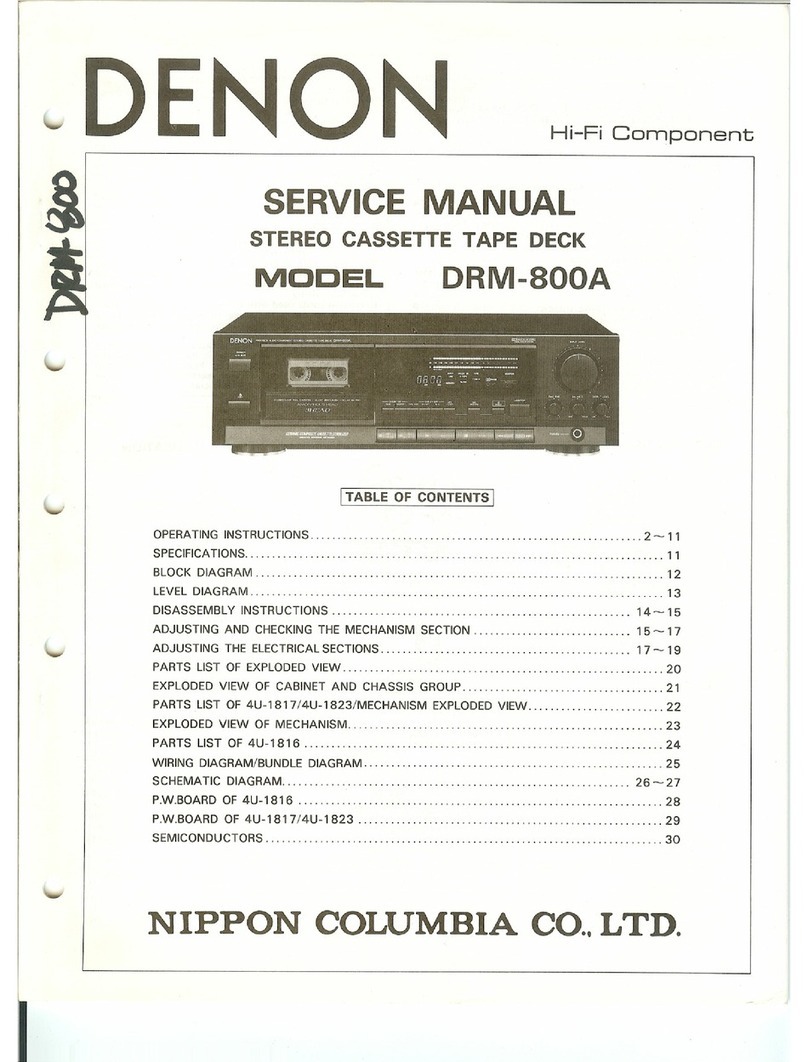
Denon
Denon DRM-400 User manual

Denon
Denon DRM-550 User manual

Denon
Denon DRM-595 User manual

Denon
Denon DRW840 - Stereo Double Cassette Deck User manual

Denon
Denon DRW-585 User manual