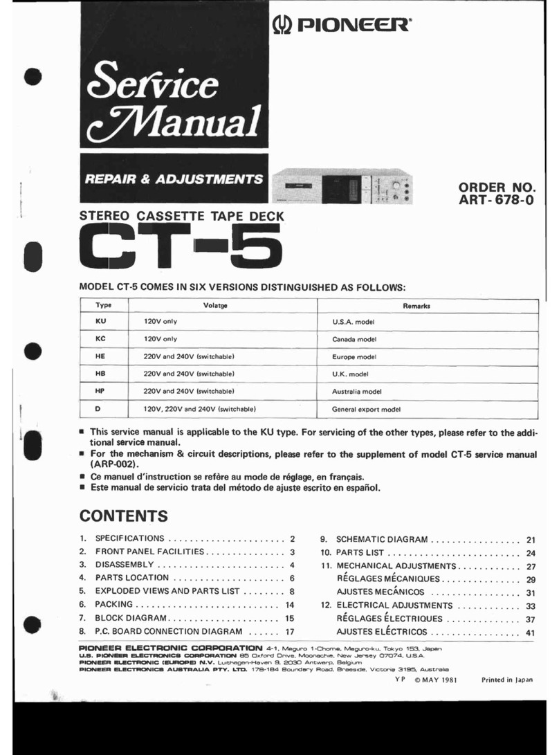
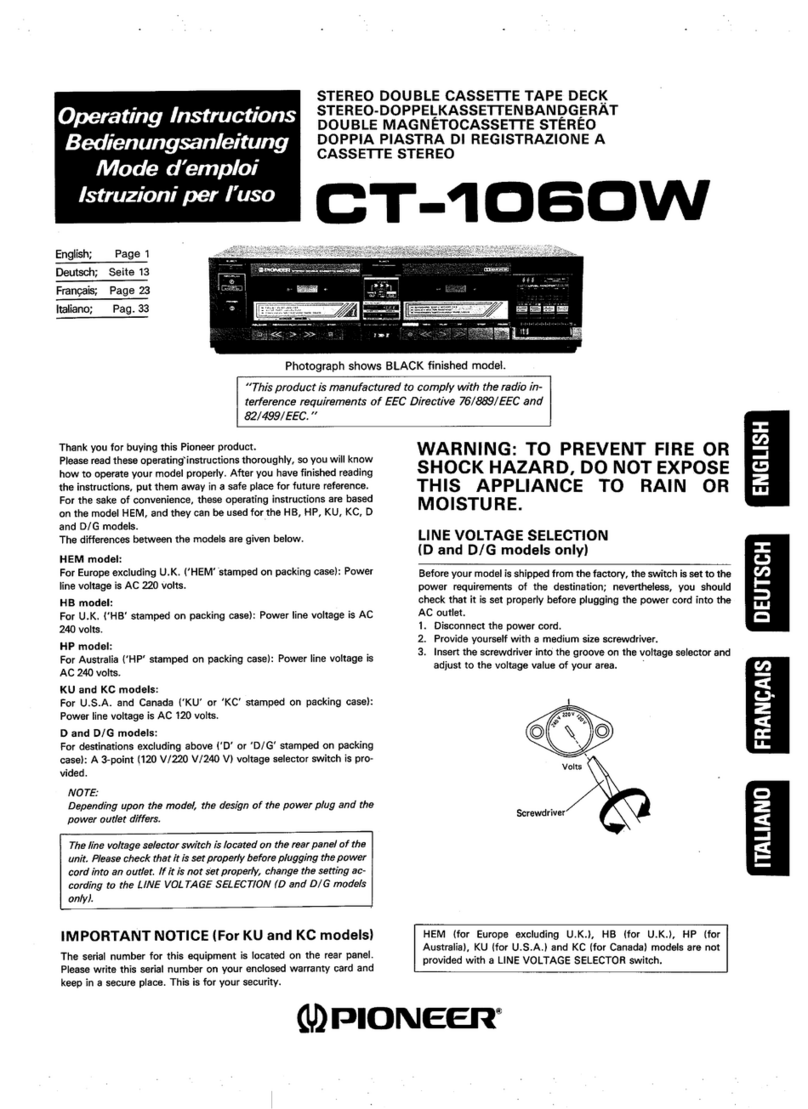
Pioneer CT-A9X User manual

Operating
Instructions
e@
Side
panels
not
supplied
with
Europe
and
U.K.
models.
@
Photograph
shows
BLACK
finished
models.
Thank
you
for
buying
this
Pioneer
product.
Please
read
these
operating
instructions
thoroughly,
so
you
will
know
how
to
operate
your
model
properly.
After
you
have
finished
reading
the
instructions,
put
them
away
in
a
safe
place
for
future
reference.
For
the
sake
of
convenience,
these
operating
instructions
are
based
on
the
model
HEM,
and
they
can
be
used
for
the
HB,
HP,
KU,
KC,
D
and
D/G
models.
The
differences
between
the
models
are
given
below.
HEM
model:
.
For
Europe
excluding
U.K.
(‘HEM’
stamped
on
packing
case):
Power
line
voltage
is
AC
220
volts.
-
HB
model:
For
U.K.
(‘HB’
stamped
on
packing
case):
Power
line
voltage
is
AC
240
volts.
HP
model:
For
Australia
(‘HP’
stamped
on
packing
case):
Power
line
voltage
is
AC
240
volts.
KU
and
KC
models:
For'U.S.A.
and
Canada
(‘KU’
or
‘KC’
stamped
on
packing
case):
Power
line
voltage
is
AC
120
volts.
D
and
D/G
models:
For
destinations
excluding
above
(‘D’
or
‘D/G’
stamped
on
packing
case):
A
3-point
(120
V/220
V/240
V)
voltage
selector
switch
is
pro-
vided.
NOTE:
Depending
upon
the
model,
the
design
of
the
power
plug
and
the
power
outlet
differs.
*
The
line
voltage
selector
switch
is
located
on
the
rear
panel
of
the
unit.
Please
check
that
it
is
set
properly
before
plugging
the
power
cord
into
an
outlet,
If
it
is
not
set
properly,
change
the
setting
of
it
according
to
the
LINE
VOLTAGE
SELECTION
(D
and
D/G
models
only).
FOATUPES
Saceiccavetciciexccdudcudsteys
cveseenstiguouedecsece’
About
the
Accessory
Wood-Grain
Side
Panels.........
Rear
Panel
Facilities
and
Connections
...............
Front
Panel
Facilities
:
Recording
AUTO
BLE
Tuning
System
Playback
;
CONTENTS
STEREO
CASSETTE
TAPE
DECK
T-“ASX
This
product
is
manufactured
to
comply
with
the
radio
inter-
ference
requirements
of
EEC
Directive
‘‘76/889/EEC.
&
82/
499/EEC”.
IMPORTANT
NOTICE
(For
KU
and
KC
models)
The
serial
number
for
this
equipment
is
located
on
the
rear
panel.
Please
write
this
serial
number
on
your
enclosed
warranty
card
and
keep
in
a
secure
place.
This
is
for
your
security.
WARNING:
TO
PREVENT
FIRE
OR
SHOCK
HAZARD,
DO
NOT
EXPOSE
THIS
APPLIANCE
TO
RAIN
OR
MOISTURE.
.
LINE
VOLTAGE
SELECTION
(D
and
D/G
models
only)
Before
your
model
is
shipped
from
the
factory,
the
switch
is
set
to
the
power
requirements
of
the
destination;
nevertheless,
you
should
check
that
it
is
set
properly
before
plugging
the
power
cord
into
the
AC
outlet.
1.
Disconnect
the
power
cord.
2.
Provide
yourself
with
a
medium
size
screwdriver.
3.
Insert
the
screwdriver
into
the
groove
on
the
voltage
selector
and
adjust
the
voltage
value
of
your
area.
Volts
Screwdriver
HEM
(for
Europe
excluding
U.K.),
HB
(for
U.K.),
HP
(for
Australia),
KU
(for
U.S.A.)
and
KC
(for
Canada)
models
are
not
provided
with
a
LINE
VOLTAGE
SELECTOR
switch.
Using
the
Accessory
Functions
..........sserereeeee
Recording
and
Playback
Using
the
Audio
Timer
Maintenance
Troubleshooting
Cassette
Tapes
Specifications
@)
PIONEER’

READ
INSTRUCTIONS
—
All
the
safety
and
operating
instructions
should
be
read
before
the
appliance
is
operated.
RETAIN
INSTRUCTIONS
—
The
operating
instruc-
tions
should
be
retained
for
future
reference.
HEED
WARNING
—
All
warnings
on
the
appliance
and
in
the
operating
instructions
should
be
adhered
to.
FOLLOW
INSTRUCTIONS
—
All
operating
and
use
instructions
should
be
followed.
WATER
AND
MOISTURE
—
The
appliance
should
not
be
used
near
water
—
for
example,
near
a
bathtub,
washbowl,
kitchen
sink,
laundry
tub,
in
a
wet
basement,
or
near
a
swimming
pool,
etc.
LOCATION
—
The
appliance
should
be
installed
in
a
P
stable
location.
WALL
OR
CEILING
MOUNTING
—
The
appliance
should
not
be
mounted
to
a
wall
or
ceiling.
VENTILATION
—
The
appliance
should
be
situated
so
that
its
location
or
position
does
not
interfere
with
its
proper
ventilation.
For
example,
the
appliance
should
not
be
situated
on
a
bed,
sofa,
rug,
or
similar
surface
that
may
block
the
ventilation
open-
ings;
or,
placed
in
a
built-in
installation,
such
as
a
bookcase
or
cabinet
that
may
impede
the
flow
of
air
through
the
ventilation
openings.
HEAT
—
The
appliance
should
be
situated
away
from
heat
sources
such
as
radiators,
heat
registers,
stoves,
or
other
appliances
(including
amplifiers)
that
produce
heat.
POWER
SOURCES
—
The
appliance
should
be
con-
nected
to
a
power
supply
only
of
the
type
describ-
ed
in
the
operating
instructions
or
as
marked
on
the
appliance.
POWER-CORD
PROTECTION
—
Power-supply
cords
should
be
routed
so
that
they
are
not
likely
to
be
watked
on
or
pinched
by
items
placed
upon
or
against
them,
paying
particular
attention
to
cords
at
plugs,
convenience
receptacles,
and
the
point
where
they
exit
from
the
appliance.
POLARIZATION
—
If
your
purchased
product
is
pro-
vided
with
a
polarized
power
plug,
please
read
the
following
instructions.
This
product
is
equipped
with
a
polarized
alternating
current
line
plug
(a
plug
having
one
blade
wider
than
the
other}.
This
plug
will
fit
into
the
power
outlet
only
one
way.
This
is
a
safety
feature.
If
you
are
unable
to
insert
the
plug
fully
into
the
outlet,
try
reversing
the
plug.
If
the
plug
shoutd
still
fail
to
fit,
contact
your
electrician
to
replace
your
obsolete
outlet.
Do
not
defeat
the
safety
purpose
of
the
polarized
plug.
CLEANING
—
The
appliance
should
be
cleaned
only
with
a
polishing
cloth
or
a
soft
dry
cloth.
Never
clean
with
furniture
wax,
benzine,
insecticides
or
other
volatile
liquids
since
they
may
corrode
the
cabinet.
IMPORTANT
1
The
lightning
flash
with
arrowhead,
within
an
equilateral
triangle,
is
intended
to
alert
the
user
of
the
presence
of
uninsulated
“dangerous
voltage”
within
the
product's
enclosure
that
may
be
of
sufficient
magnitude
to
constitute
a
risk
of
electric
shock
to
persons.
IMPORTANT
2
(f
the
apparatus
is
fitted
with
AC
mains
power
outlet(s),
see
REAR
PANEL
FACILITIES
for
convenient
connec-
tion
of
additional
Hi-Fi
component{s).
Make
all
connec-
tions
to
the
AC
outlet(s)
and
the
signal
terminals
firts.
Connect
the
plug
to
the
wall
socket
last,
make
sure
that
the
power
switch
is
off.
Disconnect
the
wal!
plug
when
the
equipment
is
not
in
(regular)
use,
e.g.
when
on
vaca-
tion,
SAFETY
INSTRUCTIONS
POWER
LINES
—
An
outdoor
antenna
should
be
located
away
from
power
lines.
NONUSE
PERIODS
—
The
power
cord
of
the
ap-
pliance
should
be
unplugged
from
the
outlet
when
left
unused
for
a
long
period
of
time.
OBJECT
AND
LIQUID
ENTRY
—
Care
should
be
taken
so
that
objects
do
not
fall
and
liquids
are
not
spilled
into
the
enclosure
through
openings.
DAMAGE
REQUIRING
SERVICE
—
The
appliance
should
be
serviced
by
Pioneer
authorized
service
center
or
qualified
service
personnel
when:
¢
The
power-supply
cord
or
the
plug
has
been
damaged;
or
: 7
®
Objects
have
failen,
or
liquid
has
been
spilled
into
the
appliance;
or
e
The
appliance
has
been
exposed
to
rain;
or
Fig.
A.
*®
The
appliance
does
not
appear
to
operate
normally
or
exhibits
a
marked
change
in
performance;
or
¢
The
appliance
has
been
dropped;
or
the
enclosure
damaged.
SERVICING
—
The
user
should
not
attempt
to
service
the
appliance
beyond
that
described
in
the
operating
instructions.
For
all
other
servicing,
con-
tact
the
nearest
Pioneer
authorized
service
center.
charges.
~~
S
><
\
GROUND
CLAMP
POWER
LINES.
SERVICE
ENTRANCE
CONDUCTORS)
+
STAND
OFF
INSULATORS
b
ANTENNA
LEAD-IN
WIRE
TO
EXTERNAL
ANTENNA
TERMINALS
OF
PRODUCT
a)
b)
c)
d)
OUTDOOR
ANTENNA
GROUNDING
—
If
an
outside
antenna
is
connected
to
the
antenna
terminal,
be
sure
the
antenna
system
is
grounded
so
as
to
provide
some
protection
against voitage
surges
and
built
up
static
In
the’U.S.A.
section
810
of
the
National
Elec-
trical
Code,
ANSI/NEPA
No.
70-1984,
pro-
vides
information
with
respect
to
proper
grounding
of
the
mast
and
supporting
struc-
ture,
grounding
of
the
lead-in
wire
to
an
anten-
na
discharge
unit,
size
of
grounding
conduc-
tors,
location
of
antenna-discharge
unit,
con-
nection
to
grounding
electrodes,
and
re-
quirements
for
the
grounding
electrode.
See
Use
No.
10
AWG
(5.3
mm?)
copper,
No.
8
AWG
(8.4
mm?)
aluminum,
No.
17
AWG
(1.0
mm?)
copper-
clad
steel,
bronze
wire,
or
larger
as
ground
wire.
Secure
antenna
lead-in
and
ground
wires
to
house
with
stand-off
insulators
spaced
from
4
feet
(1.22
meters)
to
6
feet
(1.83
meters)
apart.
Mount
antenna
discharge
unit
as
closely
as
possible
to
where
lead-in
enters
house.
Use
jumper
wire
not
smaller
GROUND
WIRE
a,b
4
GROUND
}
CLAMPS
SERVICE.ENTRANCE
EQUIPMENT
We
POWER
SERVICE
GROUNDING
ELECTRODE
SYSTEM
e.g.
interior
metal
water
pipe)
REQUIRED
BY
LOCAL
CODES.
SEt
NEC
SECTION
810-;
FIG.A
u
CAUTION
RISK
OF
ELECTRIC
SHOCK
DO
NOT
OPEN
CAUTION:
TO
PREVENT
THE
RISK
OF
ELECTRIC
SHOCK,
DO
NOT
REMOVE
COVER
{OR
BACK).
NO
USER-
SERVICEABLE
PARTS
INSIDE.
REFER
SERVIC-
ING
TO
QUALIFIED
SERVICE
PERSONNEL.
FOR
USE
IN
THE
UNITED
KINGDOM
The
wires
in
this
mains
lead
are
coloured
in
accordance
with
the
following
code:
Blue:
Neutral
Brown:
Live
ANTENNA
“
DISCHARGE
UNI
Pac
GROUND
WIRE
a,b
OPTIONAL
ANTENNA
GROUNDING
ELECTRODE
1
DRIVEN
8
FEET
(2.44
m)
SOMPER
is
INTO
THE
EARTH
IF
it
than
No.6
AWG
(13.3
mm?)
copper
or
equivalent
when
separate
antenna-ground-
ing
electrode
is
used.
The
exclamation
point
within
an
equilateral
triangle
is
intended
to
alert
the
user
of
the
presence
of
important
operating
and
maintenance
(servicing)
instructions
in
the
literature
accompanying
the
appliance.
As
the
colours
of
the
wires
in
the
mains
lead
of
this
ap-
paratus
may
not
correspond
with
the
coloured
marking
identifying
the
terminals
in
your
plug
proceed
as
follows:
The
wire
which
is
coloured
blue
must
be
connected
to
the
terminal
which
is
marked
with
the
letter
N
or
col-
oured
black.
The
wire
which
is
coloured
brown
must
be
connected
to
©
the
terminal
which
is
marked
with
the
letter
L
or
col-
oured
red.
Equipment
sold
in
the
U.K.
is
not
supplied
with
a
power
plug.

FEATURES
AUTOMATIC
SILENT-LOADING
MECHANISM
The
use
of
an
optical
cassette
detector
and
shift
mechanism
makes
possible
easy-to-operate
auto
loading
and
power
eject.
In
addition,
thorough
attention
has
been
paid
to
all
aspects
of
construction,
from
selection
of
materials
for
motor
drive
transmission
parts,
to
final
assembly,
in
order
to
assure
that
the
mechanism
operates
as
silently
as
possible.
MOL
BALANCE
CONTROL
TYPE
AUTO
BLE
Differences
in
the.
frequency
spectrum
of
the
music
source
changes
the
AUTO
BLE
bias
adjustment
point
in
3
stages.
This
allows
a
flat
fre-
quency
response
and
dynamic
range
at
the
maximum
limits
allowable
with
tape.
AUTO
BLE:
An
abbreviation
for
Automatic
Bias,
Level
and
Equalizer
Tuning
System.
MOL:
An
abbreviation
for
Maximum
Output
Level.
AUTO
MONITOR
For
simplified
operation
of
the
bothersome
monitor
switch
during
recording,
This
feature
allows
you
to.
switch
between
tape
monitor
and
source
monitor
merely
by
pressing
the
operating
switch.
FEATHERTOUCH,
EASE
OF
OPERATION
WITH
IC
LOGIC
The
unit
is
a
joy
to
operate,
with
sure,
microcomputer
digital
feedback
servo
controller
mechanism,
allowing
direct
transition
from
playback
to
fast
forward,
rewind.
TAPE
SLACK
PREVENTION
FUNCTION
With
the
tape
slack
prevention
function,
when
the
cassette
holder
closes,
the
takeup
reel
automatically
revolves
to
eliminate
any
tape
slack.
DOLBY
NR
B,
C
SYSTEMS
In
addition
to
the
previous
Dolby
B
noise
reduction
system,
the
unit
is
equipped
with
the
Dolby
NR
C
type
system
and
its
superior
noise
reduction
effect
for
even
greater
fidelity
of
sound
reproduction.
MPX
FILTER
Using
the
Dolby
NR
system,
the
MPX
filter
can
be
switched
to
ON
or
OFF
for
more
effective
noise
reduction
with
FM
stereo
broadcasts.
AUTO
RECORDING
MUTE
FUNCTION
The
automatic
recording
mute
function
creates
a
non-recorded
inter-
val
of
4
seconds
at
one
touch,
then
automatically
returning
the
unit
to
the
recording
standby
mode.
This
function
is
very
convenient
for
cut-
ting
out
commercials
and
unwanted
narration
during
FM
broadcast
recording
and
editing.
BUILT-IN
MUSIC
SEARCH
FUNCTION
The
music
search
function
is
convenient
for
locationg
a
particular
pro-
gram
on
a
tape,
or
when
performing
repeat
piay
of
a
certain
program.
DUAL
MGDE
COUNTER
The
four-digit
digital
display
can
be
used
either
as
a
real
time
counter
for
displaying
the
time
remaining
on
the
tape,
or
as
a
normal
tape
counter
display.
TIMER
FUNCTION
ALLOWS
ABSENTEE
RECORDING
OR
WAKEUP
PLAYBACK
When
used
with
an
optional
audio
timer,
you
can
wake
up
to
your
favorite
music,
or
perform
automatic
tape
tuning
and
recording
start.
The
AUTO
BLE
timer
recording
function
gives
you
more
freedom
for
recording.
CLOSED
LOOP,
DUAL
CAPSTAN
DRIVE
This
mechanism
drives
the
tape
using
two
sets
of
capstans
and
pinch
rollers.
Tape
travel
is
greatly
stabilized
in
order
to
shut
out
any
ex-
ternal
vibration.
Wow
and
flutter,
and
modulation
noise
is
reduced,
letting
you
enjoy
even
greater
clarity
of
tone.
In
the
capstan
a
quartz
PLL
D.D.
motor
is
used,
the
reel
motor
is
a
super-low
torque
ripple
coreless
type.
THREE-HEAD
SYSTEM
USING
RIBBON
SENDUST
HEADS
Since
a
3-head
system,
using
independent
recording,
playback,
and
erasing
heads
is
used,
you
can
monitor
the
playback
sound
while
recording,
thus
allowing
you
to
check
the
recording
status.
Ribbon
Sendust,
developed
through
Pioneer's
own
magnetics
technology,
is
used
in
the
combination
recording/
playback
head,
while
anoxic
cop-
per
windings
are
used
in
the
playback
head,
and
the
erasing
head
uses
a
special
alloy
with
high
efficiency
for
small
window
use.
As
a
result,
the
full
performance
of
high-output
tapes,
including
metal
tapes,
is
fully
demonstrated,
delivering
the
dynamic
energy
of
sound
with
superb
sound
quality.
DC
AMPLIFIER
A
DC
amplifier,
with
superb
tone
and
phase
characteristics
and
dynamic
range
is
used
for
the
playback
equalizer
amp.
The
first
stage
is
a
low
noise
dual
FET
differential
2-stage
type
amp,
while
the
power
section
is
a
shunt
type
+
2
power
unit
composition.

ABOUT
THE
ACCESSORY
WOOD-GRAIN
SIDE
PANELS
Cabinet
Side
panels
not
supplied
with
Europe
and
U.K.
models.
When
the
side
panels
are
used,
please
abide
by
the
following
items:
e
Use
only
the
screws
accompanying
the
side
panels
for
installation.
e
Do
not
remove
any
screws
attached
to
this
unit.
e
When
repacking
this
unit
(for
storage
or
shipment),
remove
the
side
panels
first.
Wood-grain
side
panel
Wood-grain
Front
panel
side
panel
Installation:
(1)
Use
your
fingernail,
etc.,
to
remove
the
two
plastic
rivets
—-()
(one
on
each
side)
on
the
sides
of
the
unit.
The
rivets
are
made
of
the
pair
(A)
and
(B);
be
sure
to
remove
both
(A)
—
@
and
(B)
together.
(2)
Using
the
holes
from
which
the
plastic
rivets
were
re-
moved,
attach
the
wood-grain
side
panels
to
the
unit
with
the
accessory
screws.
Be
sure
to
install
the
panels
so
that
the
wood-grain
pattern
is
on
the
outside.
DEW
CONDENSATION
When
the
unit
is
moved
from
a
cold
to
a
warm
room,
or
a
quick
NOTE:
temperature
change
occurs,
condensation
will
form
on
the
mechani-
cal
parts
affecting
performance
of
the
unit.
In
such
cases,
leave
the
unit
in
a
warmer
atmosphere
for
approximately
one
hour,
or
gradually
change
the
room
temperature.
When
locating
the
tape
deck,
do
not
place
a
cloth
over
the
top
or
block
the
ventilation
openings
in
any
other
way.
reorient
the
receiving
antenna
relocate
the
cassette
tape
deck
with
respect
to
the
receiver
move
the
cassette
tape
deck
away
from
the
receiver
plug
the
cassette
tape
deck
into
a
different
outlet
so
that
the
cassette
tape
deck
and
receiver
are
on
different
branch
circuits.
This
equipment
generates
and
uses
radio
frequency
energy
and
if
not
installed
and
used
properly,
that
is,
in
strict
accordance
with
the
manufacture’s
instructions,
may
cause
interference
to
radio
and
television
reception.
It
has
been
type
tested
and
found
to
comply
with
the
limits
for
a
Class
B
computing
device
in
accordance
with
the
specifications
in
Subpart
J
of
Part
15
of
FCC
Rules,
which
are
designed
to
provide
reasonable
protection
against
such
interference
in
a
residential
installation.
However,
there
is
no
guarantee
that
in-
terference
will
not
occur
in
a
particular
installation.
If
this
equipment
does
cause
interference
to
radio
or
television
reception,
which
can
be
determined
by
turning
the
equipment
off
and
on,
the
user
is
en-
couraged
to
try
to
correct
the
interference
by
one
or
more
of
the
following
measures:
If
necessary,
the
user
should
consult
the
dealer
or
an
experienced
radio/television
technician
for
additional
suggestions.
The
user
may
find
the
following
booklet
prepared
by
the
Federal
Communications
Comission
helpful.
“How
to
Identify
and
Resolve
Radio-TV
Interference
Problems’’.
This
booklet
is
available
from
the
US
Government
Printing
Office,
Washington,
D.C.,
20402,
Steck
No.
004-000-00345-4.
The
above
instructions
apply
only
to
units
which
will
be
operated
in
the
United
States.

REAR
PANEL
FACILITIES
AND
CONNECTIONS
Before
Connecting
#
Do
not
switch
on
the
power
until
all
the
connections
have
been
completed.
:
e
The
top
jacks
are
for
the
left
(L)
channel;
the
bottom
jacks
are
for
the
right
(R)
channel.
*®
Make
certain
the
connectors
are
pushed
all
the
way
in.
An
im-
proper
connection
or
poor
contact
will
result
in
no
sound,
or
will
degrade
the
sound.
Stereo
amplifier
©
When
installing
the
unit,
do
not
impede
heat
dissipation
by
placing
anything
such
as
a
cloth
on
the
top
panel.
¢
Read
through
the
operating
instructions
of
the
stereo
components
you
plan
to
connect
with
this
unit.
e
Set
the
stereo
amplifier’s
power
switch
to
OFF
and
its
volume
con-
trol
to
the
minimum
position.
SPEAKER
IMPEDANCE
ieee:
©
eae
Recording
connection
_
{2-line
cord
with
pin
connectors)
Under
License
of
Staar
SA
Arussets
Belqun
tb
marks
of
Dolby
Laboratories
SS
>
&
ete
SS
AZ
To
Line
output
ef¥r
tie
eae
isda
ps
For
recording
a
source
(LINE
OUT,
A
played
back
on
another
PLAY,
etc)
To
Line
input
¢=
terminals
of
other
tape
decks.
(LINE
INPUT,
REC,
etc.)
@
LINE
INPUT
TERMINALS
The
signals
to
be
recorded
are
received
here.
Connect
the
accessory
cord
to
the
amplifier’s
TAPE
REC
terminals.
@
LINE
OUTPUT
TERMINALS
The
playback
signals
are
sent
from
here
to
the
stereo
amplifier.
Con-
nect
the
accessory
cord
to
the
amplifier's
TAPE
PLAY
terminals.
©
POWER
CORD
Plug
the
power
cord
into
the
SWITCHED
AC
OUTLET
on
the
rear
panel
of
the
amplifier
or
into
an
AC
wall
socket.
tape
deck
with
this
unit.
cu,
©
@:
Playback
connection
(2-line
cord
with
pin
connectors)
swircnen
wnsertcneo
TOTAL
(GOW
MAK
Toowaan
AC
wall
socket
ea
1
For
recording
a
source
pee
ana
J
played
back
on
this unit
j=:
“~with
another
tape
deck.
Illustration
not
applicable
to
U.K.
model.
Power
supply
frequency
This
unit
employs
a
DC
motor
and
so
it
can
be
used
with
whatever
power
line
frequency
you
have
in
your
area.

FRONT
PANEL
FACILITIES
06000
009
000
6600
60
©
me
Coens
Puig
iui
I
COUT
CAT
CTT
TT
12
cee
[5
al!
o>
76!
|
e
Ed
|e:
o—
I.
:
micas
\
©>__©
|
@
EJECT
BUTTON
Press
this
button
to
open
the
cassette
door.
Whenever
inserting
or
removing
a
cassette
tape,
be
sure
that
the
power
is
turned
ON.
@
POWER
SWITCH
When
this
switch
is
depressed
power
is
turned
ON,
and
when
it
is
depressed
again,
power
is
turned
OFF.
After.
the
power
is
turned
ON,
the
unit
will
not
operate
for
a
duration
of
4
seconds
which
is
the
neccesary
time
for
the
unit
to
become
stable.
©
CASSETTE
DOOR
This
door
opens
when
the
EJECT
button
is
pressed.
Insert
cassette
tapes
with
the
visible
part
of
the
tape
downward.
When
a
cassette
tape
is
inserted,
the
cassette
door
will
automatically
close.
The
cassette
door
will
also
close
if
it
is
lightly
pressed.
Unless
the
unit
is
powered,
the
door
can
not
be
opened.
NOTE:
If
the
cassette
door
is
closed
after
turning
the
power
off,
the
next
time
the
power
is
turned
ON
and
an
operating
switch
is
pressed,
the
cassette
door
will
open
and
close
once.
This
is
in
order
to
reset
the
microprocessor
to
the
correct
condition,
and
is
not
a
malfunc-
tion.
©
STOP
SWITCH
Depress
this
switch
to
stop
the
tape
travel
and
to
release
the
operating
switches.
;
@
PLAY
INDICATOR
(>)
This
indicator
lights
when
the
PLAY
switch
is
pressed.
It
also
lights
when
the
REC
switch
is
pressed
to
set
the
unit
in
the
recording
mode.
@
PLAY
SWITCH
Depress
this
switch
to
playback
a
tape.
@
REW
SWITCH
Depress
this
switch
to
rewind
the
tape.
(The
tape
will
travel
from
right
to
left.)
©
REWIND
INDICATOR
(<<)
This
indicator
fights
when
the
rewind
switch
(REW)
is
pressed.
The
indicator
lights
also
when
the
music
search
(MS)
<<
switch
is
pressed.
@
MUSIC
SEARCH
INDICATOR
(MS)
This
indicator
lights
when
either
of
the
music
search
switches
{
<<
or
p>
)
is
pressed.
@
FAST
FORWARD
INDICATOR
(>>)
This
lights
when
the
fast
forward
(FF)
switch
is
pressed.
When
the
music
search
(MS)
switch
p>»
is
pressed,
the
indicator
also
lights.

@
FF
SWITCH
Depress
this
switch
to
send
the
tape
forward.
(The
tape
will
travel
from
left
to
right.)
*
@
LEVEL
METER
This
indicates
the
recording
level
during
recording
and
the
output
level
during
playback.
The
top
part
is
for
the
left
(L)
channel
and
the
bottom
part
for
the
right
(R)
channel.
@
DUAL
MODE
COUNTER
(COUNTER)
This
counter
has
two
functions,
‘‘tape
counter”
and
‘‘real
time
counter,”
depending
on
the
position
of
the
counter
mode
switch
(@
TIME/TAPE).
When
used
as
a
“tape
counter,”
the
figures
change
as
the
tape
travels
and
its
transport
position
is
indicated
by
a
4-digit
number.
When
the
RESET
button
is
pressed,
the
counter
is
reset
to
“0000.”
When
the
power
is
switched
on,
the
counter
functions
as
a
‘‘tape
counter.”
When
used
as
a
“real
time
counter,”’
the
remaining
time
on the
tape
during
recording
or
playback
is
indicated.
Set
the
TAPE
CAPACITY
switch
to
the
position
corresponding
to
the
type
of
tape
(length,
hub
diameter)
being
used.
For
further
details
on
the
dual
mode
counter,
refer
to
page
15.
@
TAPE
CAPACITY
SWITCH
(TAPE
CAPACITY)
When
the
dual
mode
counter
is
used
as
a
real
time
counter,
this
switch
is
set
in
accordance
with
the
tape
type
(tape
length,
hub
diameter).
L46
.....
For
C-46
large
hub
diameter
tapes.
46
......
For
C-46
tapes.
60
......
For
C-60
tapes.
90
......
For
C-90
tapes.
NOTE:
For
tapes
other
than
those
listed
above,
set
to
the
position
nearest
to
the
actual
length
of
the
tape
used.
In
those
cases,
there
may
be
some
difference
in
the
time
displayed.
@
RESET
BUTTON
(RESET)
Press
this
to
reset
the
tape
counter
to
0000.”
Before
recording
or
playback,
press
this
button
to
reset
the
tape
counter
to
‘’0000.”
It
will
then
be
easy
to
find
programs
on
the
tape
if
a
note
is
made
of
the
tape
counter
numbers
and
of
the
recording
or
playback
con-
tents.
The
numbers
provide
you
with
a
guideline
for
finding
pro-
grams
afterward
which
you
want
to
listen
to.
The
tape
counter
can
be
reset
while
being
used
as
a
real
time
counter,
however
“0000”
is
displayed
only
while
the
RESET
button
is
depressed.
'
@
TAPE
RETURN
SWITCH
(TAPE
RETURN)
When
this
switch
is
pressed,
the
fast
forward
or
rewind
functions
will
begin,
sending
the
tape
to
the
‘0000’
position,
where
it
will
automatically
stop.
This
is
a
convenient
function
when
you
wish
to
listen
immediately
to
a
program
you
have
just
recorded,
or
when
you
wish
to
perform
repeat
play
of
a
certain
program.
COUNTER
MODE
SWITCH
(@
TIME/TAPE)
Push
this
switch
to
select
the
dual
mode
counter
function.
REC
MASTER
VOLUME
CONTROL
(REC
MASTER)
This
control
is
for
adjusting
general
recording
levels.
The
recording
level
increases
when
the
control
is
turned
clockwise,
and
decreases
_when
turned
counter-clockwise.
The
control
is
equipped
with
a
memory
marker
useful
for
remembering
a
predetermined
volume
level,
for
example
when
performing
fade-in.
@
REC
LEVEL
PRESET
VOLUME
CONTROLS
(REC
LEVEL
PRESET)
These
are
normally
set
in
the
click
position
(W).
After
setting
the
general
recording
level
with
the
recording
master
volume
control,
these
controls
can
be
used
to
finely
tune
the
R
and
L
channels’
volume
levels.
The
recording
level
is
increased
when
the
controls
are
turned
in
the
(+)
direction,
and
reduced
when
the
controls
are
turn-
ed
in
the
(—)
direction.
@
TIMER
SWITCH
(TIMER)
This
switch
is
used
when
an
optional
audio
timer
is
utilized
for
unat-
tended
recording
or
wakeup
playback
(refer
to
page
16).
NOTE:
The
timer
switch
should
always
be
in
the
OFF
position
when
not
performing
timer
recording
or
playback.
If
a
cassette
tape
is
in-
serted
and
the
switch
is
set
to
the
REC
or
PLAY
position,
the
unit
will
automatically
enter
the
recording
or
playback
mode
whenever
the
power
switch
is
turned
on.
@
BIAS
SWITCH
(Connected
to
TIMER
SWITCH)
Depending
on
the
program
source
to
be
recorded,
this
switch
can
be
set
in
3
positions
to
adjust
the
peak
bias
in
a
+
15%
range.
When
you
wish
to
emphasize
high
ranges
or
low
ranges,
you
can
choose
a
setting
with
deeper
(more)
or
shallower
(less)
bias.
When
bias
is
shallow,
the
high
ranges
are
extended,
but
distortion
increases
in
proportion.
Conversely
when
bias
is
deepened,
the
high
ranges
fall
off,
but
distortion
is
lessened.
UNDER:
Set
to
this
position
for
recording
music
such
as
rock
music
with
wide
dynamic
range
in
the
high
ranges,
and
substantial
modulation
of
sounds.
PEAK
:
For
recording.
most
general
kinds
of
music.
OVER:
Set
to
this
position
when
you
wish
to
record
classic
and
other
similar
music
with
increased
middle
and
low
range
MOL,
and
low
distortion.
NOTE:
This
switch
operates
when
the
TIMER
switch
is
set
to
the
REC
position.
@
PHONES
JACK
This
is
the
output
jack
for
the
stereo
headphones.
@
RECORDING
INDICATOR
(@)
This
lights
when
the
unit
is
set
to
the
recording
mode.

FRONT
PANEL
FACILITIES
@
REC
SWITCH
This
switch
is
pressed
for
recording.
When
the
switch
is
pressed,
the
tape
deck
is
placed
in
the
recording
standby
mode,
and
the
pause
indicator
(
Ml
),
play
indicator
(>)
and
recording
indicator
(@)
will
light.
To
begin
recording,
press
the
PAUSE
switch
to
release
from
the
recording
standby
mode.
NOTE:
®
The
switch
cannot
be
placed
in
the
ON
position
if
the
acciden-
tal
erasure
prevention
tab
on
the
cassette
have
been
broken
off,
or
if
no
cassette
is
in
the
unit.
©
To
release
the
tape
deck
from
the
recording
mode,
press
the
STOP
switch.
@
MUSIC
SEARCH
SWITCH
(MS)
This
switch
is
pressed
when
searching
for
the
beginning
of
pro-
grams
(Refer
to
page
14).
@
PAUSE
INDICATOR
(
ae
)
This
indicator
lights
when
the
PAUSE
switch
is
pressed.
It
also
lights
when
the
REC
switch
is
pressed.
@
PAUSE
SWITCH
Depress
this
switch
to
stop
the
tape
travel
temporarily
during
recor-
ding
or
playback.
Depress
this
switch
again
to
allow
the
tape
to
con-
tinue
to
travel.
The
tape
does
not
stop
during
fast
forward
or
rewind
operations
even
when
the
PAUSE
switch
is
depressed.
@
REC
MUTE
SWITCH
(REC
MUTE)
When
the
unit
is
in
the
recording
mode,
if
this
switch
is
pressed,
4
seconds
of
non-recorded
interval
will
be
created
automatically.
This
can
be
used
for
eliminating
unwanted
portions
during
recording,
or
for
producing
an
appropriate
non-recorded
interval
between
pro-
grams.
(Refer
to
page
14.)
Be
careful
not
to
press
this
swich
except
when
necessary.
@
RECORDING
MUTE
INDICATOR
(0)
This
indicator
flashes
when
the
REC
MUTE
switch
is
pressed
to
create
an
automatic
4
second
non-recorded
portion.
When
a
non-
recorded
portion
longer
than
4
seconds
is
created,
the
indicator
changes
from
flashing
to
steadily
lighted.
@
AUTO
MONITOR
SWITCH
(AUTO
MONITOR)
This
unit
is
equipped
with
an
automatic
monitor
function.
This
means
that
when
the
unit
is
in
the
recording
standby
mode,
SOURCE
MONITOR,
or
when
in
the
playback
mode,
TAPE
MONITOR
is
automatically
selected.
However,
when
you
wish
to
select
TAPE/SOURCE
monitoring
manually,
this
switch
can
be
pressed.
When
the
switch
is
pressed,
the
unit
will
switch
to
the
mode
opposite
to
that
of
prior
to
pressing
the
switch.
For
example,
if
the
unit
is
in
the
TAPE
MONITOR
mode
before
the
switch
is
press-
ed,
it
will
switch
to
the
SOURCE
MONITOR.
The
[TAPE]
—
MONITOR—
indicators
in
the
level
meter
will
light
to
show
the
monitoring
mode.
@
BIAS
SWITCHES
(UNDER
BIAS,
PEAK
BIAS,
OVER
BIAS)
These
switches
are
used
when
adjusting
the
AUTO
BLE
to
choose
an
under,
peak,
or
over
bias
point.
When
these
switches
are
press-
ed,
the
AUTO
BLE
operation
begins.
During
BLE
adjustment,
the
in-
dicators
above
the
switches
flash
as
appropriate.
When
BLE
adjust-
ment
is
completed,
the
indicator
for
the
appropriate
switch
lights
steadily.
In
order
to
protect
against
mistaken
operation,
the
BLE
operation
will
not
start
even
if
the
switches
are
pressed
unless
the
unit
is
in
the
stap
condition.
@
AUTO
BLE
CLEAR
SWITCH
(CLEAR)
When
this
switch
is
pressed,
the
data
set
by
the
AUTO
BLE
system
are
cleared.
After
clearing,
the
bias,
level
and
equalization
are
all
set
to
the
standard
values
selected
by
the
auto
tape
selector.
NOTE:
When
the
unit
is
in
the
recording,
playback,
recording
standby,
or
playback
standby
mode,
data
will
not
be
cleared
even
if
the
clear
switch
is
pressed.
To
clear
data,
perform
this
operation
with
the
unit
in
the
stop
mode.
MULTIPLEX
FILTER
SWITCH
(MPX
FILTER)
Push
this
switch
when
recording
FM
stereo
broadcasts
or
TV
pro-
grams
using
the
Dolby
noise
reduction
system.
Contained
among
the
FM
stereo
signals
are
a
19
kHz
pilot
signal
and
the
38
kHz
subcarrier.
The
MPX
FILTER
switch
is
pressed
in
order
to
safeguard
against
incorrect
operation
of
the
Dolby
circuit
due
to
these
signals.
Release
the
switch
for
any
other
recording.
The
switch
does
not
function
during
playback.
€
DOLBY
NR
SWITCH
(DOLBY
NR
ON/OFF)
Press
this
switch
ON
when
using
the
Dolby
NR
system
for
recording
or
playback.
When
the
Dolby
NR
system
is
ON,
the
Dolby
indicator
B
or
C
lights.
FV
ava
Vin
"a
a
tata
aa
A
ATA ATA
TA TA
TATA TATA
ATA
TA
TAA
TAA
CA
Th
th
ah
aA
A
aA
cia
“Dolby”
and
the
double-D
symbol
are
trademarks
of
Dolby
Laboratories
Licensing
Corporation.
Noise
Reduction
manufactured
under
license
from
Dolby
Laboratories
Licensing
Corporation.
IOUT
vavata
ta
tata
tata
aA
A
TATA
A
ATA
TATA
AA
TATA
A
ATA
ACA
dh
ddd

@
DOLBY
B/C
SELECTOR
SWITCH
(DOLBY
NR
B/C)
This
deck
is
equipped
both
type
B
and
type
C
Dolby
noise
reduction
systems.
After
the
DOLBY
NR
ON/OFF
switch
is
pressed,
select
type
B
or
C
using
this
switch.
The
Dolby
indicator
corresponding
to
the
switch
position
lights.
|
&
OUTPUT
LEVEL
VOLUME
CONTROLS
(OUTPUT
LEVEL)
These
controls
are
for
adjusting
the
deck’s
output
level.
When
the
controls
are
turned
clockwise,
output
level
is
increased.
(Refer
to
page
13.)
PHONES
...
Adjusts
output
level
at
headphones
jack.
LINE
OUT
...
Adjusts
output
level
at
LINE
OUTPUT
(PLAY)
ter-
minals
on
the
rear
panel.
NOTE:
©
The
movement
of
the
level
meters
is
not
affected
by
rotation
of
the
output
level
volume
controls.
e
/f
the
output
level
control
is
set
at
the
minimum
“0”
position,
no
sound
will
be
heard,
even
if
the
amplifier’s
volume
control
is
rotated.
e
/f
the
PHONES
volume
control
is
set
at
the
minimum
“0”
posi-
tion,
no
sound
will
be
heard
from
headphones.
€
MONITOR
INDICATOR
(MONITOR)
This
indicator
shows
the
monitoring
mode
selected
by
the
automatic
monitoring
function.
@
TAPE
CAPACITY
INDICATOR
This
indicator
shows
the
type
of
tape
selected
with
the
TAPE
CAPACITY
switch.
©
TAPE
INDICATORS
(NORM/CrO,/METAL)
This
mechanism
uses
the
sensor
holes
on
the
cassette
to
detect
the
type
of
tape
being
used.
It
then
automatically
adjusts
the
proper
recording
bias
and
equalization
for
the
tape.
The
type
of
tape
is
then
shown
on
the
tape
indicator.
Refer
to
page
19
for
the
different
types
of
cassette
tapes
and
their
hole
positions.
NORM:
_
This
indicator
lights
when
normal
tapes
are
used.
CcrO,:
This
indicator
lights
when
CrO,
tapes
are
used.
METAL:
This
indicator
lights
when
metal
tapes
are
used.
NOTE:
When
using
metal
tapes
without
sensor
holes,
the
tape
selector
will
be
set
on
the
CrO,
position.
In
this
case,
optimum
recording
and
erasure
may
not
be
possible.
We
thus
recommend
that
you
use
metal
tapes
with
sensor
holes.
Pre-recorded
metal
tapes
can
be
played
as
is
on
this
unit.
BIAS,
LEVEL,
EQ
ADJUSTMENT
IN-
DICATORS
The
AUTO
BLE
performs
adjustments
in
the
order
bias
=»
level
=
equalizer.
The
BIAS,
LEVEL,
and
EQ
indicators
light
in
order
together
with
the
adjustment
process.
When
the
equalizer
adjust-
ment
is
completed,
the
indicators
go
out.
@
DOLBY
INDICATORS
(DOLBY
NR)
These
light
when
the
DOLBY
NR
switch
is
set
to
ON
.
[B]:
This
lights
when
the
B
type
Dolby
noise
reduction
system
is
operating.
[C]:
This
lights
when
the
C
type
Dolby
noise
reduction
system
is
operating.
@
MULTIPLEX
INDICATOR
(MPxX)
This
indicator
lights
when
the
Multiplex
filter
(MPX
FILTER)
switch
is
pressed
ON.
@®
BIAS
INDICATORS
In
accordance
with
the
setting
of
the
bias
switches,
these
indicators
flash
during
AUTO
BLE
adjustment,
and
light
steadily
when
adjust-
ment
is
completed.
(Refer
to
page
12.)
-
@
HEAD
CLEANING
ACCESS
PORT
(Refer
to
page
17)
About
Transparent
Tape
Cassettes
This
unit
is
equipped
with
an
automatic
loading
device
which
optically
detects
the
presence
of
a
tape
cassette
in
the
cassette
holder,
thus
causing
the
cassette
door
to
automatically
close.
©
Some
tape
cassettes
are
made
from
a
transparent
plastic
material.
The
unit's
auto
loading
device
may
not
operate
properly
when
these
transparent
tape
cassettes
are
used.
e
In
this
event,
press
the
cassette
door
slightly
with
your
finger,
or
use
one
of
the
direct
operating
switches
(recording
switch
or
playback
switch)
to
close
the
cassette
door.

RECORDING
Is
the
power
cord
correctly
connected
to
an
outlet?
Are
connecting
cords
and
wires
connected
correctly?
Is
the
TIMER
switch
set
to
the
OFF
position?
Are
the
accidental
erasure
prevention
tabs
broken
off
of
the
tape
cassette?
Load
the
cassette
tape
2]
for
the
recording.
e
lf
using
metal
or
chromium
dioxide
tapes,
does
the
tape
cassette
have
sensor
holes?
e
ls
the
program
source
ready
to
be
recorded?
When
using
the
AUTO
BLE
system
for
recording,
refer-to
the
sec-
tion
on
AUTO
BLE
on
page
12.
@
Depress
the
POWER
switch
to
ON.
@
Press
the
EJECT
button
to
open
the
cas-
sette
door.
With
the
exposed
tape
surface
pointing
down,
insert
an
unrecorded
tape.
The
auto
loading
function
will
close
the
cassette
door
automatically.
Also,
if
the
tape
has
any
slack,
the
tape
slack
prevention
function
will
operate
to
take
up
any
slack.
©
Select
the
DOLBY
NR
switch
positions.
When
recording
material
using
the
Dolby
Noise
Reduction
System,
press
the
DOLBY
NR
(ON/OFF)
switch
to
the
ON
posi-
tion.
Then
select
type
B
or
C
using
the
DOLBY
NR
(B/C)
switch.
NOTE:
Set
the
Multiplex
filter
(MPX
FILTER)
ON
when
recording
FM
broadcast
with
Dolby
NR
system.
@
Press
the
REC
switch.
When
this
switch
is
pressed,
the
tape
deck
is
placed
in
the
recor-
ding
standby
mode,
and
the
recording
indicator
(
@
),
the
play
in-
dicator
(»
)and
the
pause
indicator
(
BM
)
will
light.
The
auto
monitor
will
switch
to
the
source
monitor
([SOURCE
|
display
will
light).
@
Adjust
the
recording
level.
Adjust
the
recording
level
with
the
REC
MASTER
volume
con-
trol.
Fine
adjustment
of
the
left
and
right
channel
is
done
with
the
REC
LEVEL
PRESET
volume
control.
10
Temporarily
stop
the
tape
run
@
When
PAUSE
switch
is
pressed,
the
standby
mode
is
cancelled
and
recording
starts.
The
auto
monitor
will
automatically
switch
to
tape
monitor
(TAPE)
display
will
light).
@
Press
the
STOP
switch
to
stop
the
recor-
ding.
To
temporarily
stop
the
recording,
press
the
PAUSE
switch.
To
resume
recording,
press
the
PAUSE
switch
again.
©
Press
the
EJECT
button
to
open
the
cassette
door
and
remove
the
cassette
tape.
Lightly
close
the
cassette
door
with
your
finger
after
removing.
the
cassette
tape.
Cautions
with
recording
~
¢
The
D0
mark
on the
meter
scale
indicates
the
reference
level
of
the
Dolby
noise
reduction
system.
e
In
actual
fact,
the
proper
recording
level
differs
slightly
accor-
ding
to
the
type
of
tape,
the
sound
and
the
music
being
record-
ed.
In
order
to
make
the
most
of
the
tape’s
characteristics
and
produce
good-quality
recordings,
it
is
important
to
check
the
sound
yourself
by
ear.
¢
The
level
meter
may
light
up
in
a
different
way
for
recording
and
playback.
This
is
caused
by
the
difference
in
the
tape’s
sensitivity
and
a
slight
deviation
in
this
respect
does
not
pose
any
problems.
J

ADJUSTING
THE
RECORDING
LEVEL
The
adjustment
of
the
recording
level
is
an
important
factor
in
achiev-
ing
good
recording
results.
A
high
level
is
good
for
the
signal-to-noise
ratio
and
the
dynamic
range
but
an
excessively
high
level
distorts
the
-
sound.
If
the
level
is
made
too
low
out
of
fear
of
distorting
the
sound,
irritating
tape
hiss
will
mar
the
recording.
Depending
on
the
manufac-
turer
and
type
of
tape,
the
characteristics
of
a
tape
differ
even
when
_
the
same
kind
is
used.
Making
a
setting
to
just
near
the
tape’s
max-
imum
recording
level
will
do
full
justice
to
a
tape’s
characteristics
and
result
in
a
good-quality
recording.
When
INPUT
level
controls
can
also
be
used
to
fade
in
the
sound
where
the
recording
level
is
gradually
increased
or
to
fade
out
the
sound
where
the
level
is
gradually
reduced.
Using
normal
tapes
(NORM)
Adjust
the
controls
so
that
“+3
dB”
designated
by
“
O00
”
lights
up
from
time
to
time
with
the
strongest
input
signals.
It
does
not
matter
if
“4
6
dB”
also
lights
momentarily.
Using
chrome
tapes
(CrO,)
Adjust
the
controls
so
that
‘’+
3
dB”
designated
by
“’
OO
”
lights
up
from
time
to
time with
the
strongest
input
signals.
It
does
not
mat-
ter
if
‘+
6
dB”
also
lights
momentarily.
Using
metal
tapes
(METAL)
Adjust
the
controls
so
that
“+
5
dB”
lights
up
from
time
to
time
with
the
strongest
input
signals.
It
does
not
matter
if
"+
8
dB”
also
lights
momentarily.
ERASING
RECORDED
SOUND
When
a
new
recording
is
made
on
a
previously
recorded
tape,
the
old
recording
is
automatically
erased
as
the
new
recording
is
made.
To
erase
the
old
recording
without
making
a
new
recording,
perform
the
following:
1.
Check
that
the
accidental
erasure
prevention
tabs
have
not
been
broken
off
of
the
tape
cassette.
If
the
tabs
are
broken,
cover
the
holes
with
celophane
tape.
(Refer
to
page
19).
2.
Load
the
tape
in
the
cassette
holder
with
the
side
to
be
erased
fac-
ing
you.
3.
Rotate
either
the
REC
MASTER
volume
control
or
the
REC
LEVEL
PRESET
volume
control
fully
to
the
left
(counter-clockwise).
4.
Press
the
REC
switch.
Press
the
PAUSE
switch
to
release
the
unit
from
the
recording
standby
mode,
and
begin
the
recording.
In
this
way,
the
previous
contents
will
be
completely
erased.
ABOUT
THE
POWER
EJECT/AUTO
LOADING
FUNCTION
In
this
unit,
the
opening
and
closing
of
the
cassette
door
is
controlled
automatically
by
the
power
eject/auto
loading
function.
Be
sure
to
in-
stall
the
deck
in
a
location
which
will
not
interfere
with
the
opening
and
closing
of
the
cassette
door.
A
safety
device
connected
to
the
built-in
microprocessor
operates
if
the
cassette
door
is
prevented
from
opening
or
closing
fully.
In
these
cases,
eject,
loading,
and
other
operations
cannot
be
performed.
Check
the
source
of
the
problem
before
operating
again.
ABOUT
THE
3-HEAD
SYSTEM
AND
AUTO
MONITORING
A
3-head
system
is
the
combination
of
three
independent
heads
(recording,
playback,
erasure)
together
with
recording
and
playback
amplifiers.
Such
3-head
systems
are
equipped
with
a
MONITOR
switch
to
allow
switching
between
the
recording
amplifier
and
playback
amplifier.
When
switched
to
SOURCE,
the
signals
being
recorded
can
be
monitored.
When
set
to
TAPE,
the
signals
recorded
on
the
tape
can
be
monitored.
This
deck
is
equipped
with
an
automatic
monitor
function
which
automatically
switches
to
the
appropriate
mode
depending
on
the
set-
ting
of
the
operating
switches.
When
in
the
recording
and
playback
mode,
the
deck
switches
automatically
to
tape
monitor,
and
when
in
recording
standby
mode,
the
deck
switches
to
source
monitor.
During
recording,
by
performing
simultaneous
monitoring
(in
the
tape
monitoring
mode),
you
can
play
back
and
monitor
signals
even
as
they
are
being
recorded,
thus
allowing
you
check
for
optimum
recor-
ding
levels.
AUTO-STOP
MECHANISM
When
the
tape
comes
to
the
end
and
is
fully
wound
up
in
the
playback,
recording,
fast
forward
or
rewind
mode
or
when
the
tape
is
fully
rewound,
the
mode
is
automatically
released
and
the
tape
is
stopped
by
the
auto-stop
mechanism.
This
mechanism
prevents
the
tape
from
becoming
elongated
and
the
pinch
rollers
from
being
deformed.
FAST
FORWARDING
The
tape
is
rapidly
forwarded
from
the
left
reel
to
the
right
reel
when
the
FF
switch
is
depressed.
When
the
tape
is
forwarded
to
its
end,
the
auto-stop
mechanism
is
activated
and
the
tape
stops.
Depress
the
STOP
switch
to
stop
a
fast
forwarding
operation.
REWINDING
The
tape
is
rapidly
rewound
from
the
right
reel
to
the
left
reel
when
the
REW
switch
is
depressed.
When
the
tape
is
rewound
to
its
end,
the
auto-stop
mechanism
is
activated
and
the
tape
stops.
Depress
the
STOP
switch
to
stop
a
rewinding
operation.
11

AUTO
BLE
TUNING
SYSTEM
This
deck
is
equipped
with
an
auto
tape
selection
function
which
automatically
sets
recording
characteristics
to
the
type
of
tape
being
used.
However,
commonly
marketed
tapes
have
unique
characteristics
depending
on
type,
and
even
tapes
of
the
same
type
may
have
subtle
differences
of
sensitivity,
frequency
response,
max-
imum
output
level,
and
operating
bias,
depending
on
the
maker.The
AUTO
BLE
function
allows
you
to
get
the
most
out
of
each
tape’s
characteristics,
automatically
setting
and
memorizing
the
optimum
recording
characteristics.
1.
Press
the
POWER
switch
to
turn
on
the
power.
2.
Insert
a
tape
you
wish
to
adjust
for
AUTO
BLE
into
the
cassette
holder.
The
automatic
tape
selection
function
will
detect
the
type
of
tape
used,
and
will
show
that
tape
type
in
the
tape
indicator.
3.
Press
the
bias
switches
in
accordance
with
the
program
source
to
be
recorded
(OVER,
PEAK,
UNDER).
4.
The
deck
will
automatically
enter
the
recording
mode,
and
‘’tun-
ing”
of
the
tape
will
begin.
The
AUTO
BLE
indicators
will
light
in
order.
5.
The
tuning
process
will
be
completed
in
about
11
seconds,
after
which
the
tape
will
be
automatically
rewound
to
a
point
just
past
the
start
point.
The
indicator
above
the
switch
selected
lights,
and
the
optimum
recording
characteristics
is
memorized.
The
mechanism
then
enters
the
stop
mode.
Order
in
which
indicators
light:
DOLBY
NR
ON/OFF
[_]:
steadily
lighted
:
flashing
-Advantages
of
AUTO
BLE
In
order
to
get
the
best
possible
tape
performance
during
recor-
ding,
it
is
necessary
to
set
bias,
recording
level
(recording
sensitivi-
ty)
and
equalization
to
the
levels
optimum
for
each
tape
used.
On
most
previous
tape
decks,
standard
values
were
set
for
average
tapes,
thus
even
when
the
tape
selector
was
set
for
the
‘‘proper”’
position,
delicate
nuance
differences
between
tapes
could
not
be
matched.
In
addition,
the
use
of
bias
equalization
fine-tuning
con-
trols
to
tune
tapes
audibly
was
very
difficult
to
perform
accurately,
requiring
a
good
deal
extra
time
and
trouble.
in
contrast,
the
AUTO
BLE
system
uses
a
microprocessor
to
perform
these
ad-
justments
automatically.
12
NOTE:
e
When
the
same
tape
is
“tuned”
2
or
3
times,
the
previous
memorized
tunings
will
be
erased,
and
only
the
last
optimum
recording
characteristics
will
be
memorized.
When
the
power
switch
is
turned
off,
all
memory
is
erased.
Be
sure
to
break
off
the
accidental
erasure
prevention
tabs
of
recorded
tapes.
/f
a
recorded
tape
with
its
erasure
prevention
tabs
in
place
is
loaded
in
the
deck
and
the
bias
switch
is
pressed
by
mistake,
the
AUTO
BLE
operation
will
be
initiated,
and
the
tape’s
recorded
contents
will
be
erased.
e
/fthe
AUTO
BLE
operation
is
begun
with
the
tape
fully
wound
to
its
beginning
(with
leader
tape
exposed),
following
completion
of
AUTO
BLE,
the
tape
will
be
rewound
to
a
point
just
prior
to
the
start
of
the
tape’s
magnetic
portion.
As
a
result,
this
position
on
the.
counter
may
not
exactly
match
the
counter’s
initial
star-
ting
position.
©
When
reversing
a
tape
to
perform
recording
from
side
A
to
side
Blor
vice
versa),
the
AUTO
BLE
value
is
still
memorized
and
so
it
is
not
necessary
to
perform
the
AUTO
BLE
tuning
operation
on
the
second
side.
©
To
clear
the
data
set
by
the
AUTO
BLE
tuning
operation,
press
the
CLEAR
switch.
°
There
are
times
when
the
tape
characteristics
will
not
be
memorized
(the
indicator
above
the
BIAS
switch
will
not
light)
depending
on
the
tape.
In
such
a
case,
wind
the
tape
to
another
position
using
the
PEAK
BIAS
BLE
and
perform
the
operation
once
again.
If
the
tape
characteristics
still
are
not
memorized,
operate
the
system
in
the
standard
value
mode
(the
state
in
which
the
indicator
is
not
lit).
DOLBY
TYPES
B
AND
C
The
tape
hiss
(noise
mainly
in
the
high-frequency
range)
heard
when
a
recorded
tape
is
played
back
can
be
very
irritating.
This
is
particularly
the
case
in
pianissimo
treble
sections
where
violins,
for
instance,
are
heard
in
an
orchestral
piece.
The
Dolby
noise
reduc-
tion
system
was
developed
in
order
to
reduce
this
tape
hiss.
The
Dolby
type
B
system
is
already
widely
used
for
noise
reduction
but
this
unit
features
not
only
this
type
but
also
type
C.
What
the
system
does
is
this:
when
the
midrange
and
treble
sec-
tions,
where
the
tape
hiss
is
noticeable,
are
lower
than
the
prescrib-
ed
level,
it
records
those
sections
at
a
level
higher
than
the
recor-
ding
level
at
the
‘OFF’
position
of
the
Dolby
system.
During
playback,
the
level
is
reduced
by
an
amount
equivalent
to
this
in-
crease
and
the
sound
is
played
back
with
a
reduction
in
tape
hiss.
This
operation
is
performed
automatically
in
accordance
with
the
strength
of
the
input
signals,
and
it
is
possible
to
improve
the
signal-to-noise
ratio
at
frequencies
over
5
kHz
by
about
10
dB.
As
a
result,
the
system
is
really
effective
for
the
recording
and
playback
of
ordinary
broadcasts
and
records,
etc.
However,
when
recording
a
program
source
with
a
wide
dynamic
range,
a
greater
reduction
in
the
noise
is
required.
It
was
for
this
reason
that
the
Dolby
type
C
system
was
developed.
The
big
difference
between
type
B
and
type
C
is
that
the
improve-
ment
in
the
high-frequency
range
noise
is
approximately
a
high
19
dB,
compared
with
the
‘‘OFF”
position
of
the
Dolby
system,
and
that
the
dynamic
range
is
extended
without
causing
the
sound
quality
to
change
(without
generating
breathing
noise).
¢
A
note
should
be
made
of
each
tape
recorded
with
the
Dolby
system
so
that
it
is
not
mistakenly
played
back
with
the
Dolby
system
off.
e
Always
play
back
tapes
with
the
same
Dolby
function
which
was
used
when
they
were
recorded.
Playing
back
a
tape
recorded
with
the
Dolby
system
at
the
OFF
(non-Dolby)
position
or
playing
back
a
normal
tape
with
the
Dolby
system
will
not
result
in
the
faithful
reproduction
of
the
original
sound.

PLAYBACK
e
Is
the
power
cord
properly
plugged
into
the
outlet?
e
Js
the
amplifier
properly
set
for
tape
playback?
2
}
Load
the
cassette
tape
to
be
played
back.
e
Is
the
TIMER
switch
set
to
the
OFF
position?
e
Are
all
connecting
cords
properly
connected?
oe
OlCa9
eI
iii
iii
ee
©)?
@
Depress
the
POWER
switch
to
ON.
@
Press
the
EJECT
button
to
open
the
cassette
door.
With
the
tape
surface
facing
down,
insert
a
tape
for
playback.
‘The
automatic
loading
function
will
automatically
close
the
cassette
door.
Also,
if
there
is
any
slack
in
the
tape,
the
tape
slack
prevention
function
will
operate
to
take
up
any
such
slack.
@
In
accordance
with
the
conditions
under
which
the
tape
was
recorded,
press
the
appropriate
Dolby
NR
switches
(DOLBY
NR
ON/OFF),
and
Dolby
NR
B/C
selector
switch.
@
Press
the
PLAY
switch.
The
auto
tape
monitor
function
will
automatically
switch
to
tape
monitor
({TAPE
|
display
will
light.).
@
Adjust
output
level
with
the
LINE
OUT-
PUT
volume
control.
Output
from
the
LINE
OUTPUT
(PLAY)
terminals
is
adjusted
with
the
LINE
OUTPUT
volume
control.
@
Press
the
STOP
switch
to
stop
the
playback.
To
temporarily
stop
the
playback,
press
the
PAUSE
switch.
To
resume
playback,
press
the
PAUSE
switch
again.
@
Press
the
EJECT
button
to
open
the
cassette
door,
and
remove
the
cassette
tape.
After
removing
the
cassette
tape,
to
close
the
cassette
door,
press
it
lightly
with
your
finger.
=a
oe
—
ce
a]
~—
mas
_
COIN
Ee
p
att
ae
SEED
me
7
SARA
Sate
$
6.560
5
8
og
oe
]
a;
Adjust
the
sound
volume
through
the
headhones.
ADJUSTING
OUTPUT
LEVEL
The
output
level
adjustment
control
(LINE
OUTPUT)
is
used
to
control
output
levels
so
that
the
sound
remains
proportionate
when
switching
from
the
tape
deck
to
another
source
(FM
broadcasts,
records,
etc.),
even
when
the
amplifier’s
volume
is
left
unchanged.
For
example,
when
listening
through
speakers
with
the
tape
deck
and
FM
tuner
connected
to
the
amplifier.
1.
Set
the
amplifier’s
monitor
switch
to
SOURCE,
set
the
input
selec-
tor
to
TUNER,
and
listen
to
an
FM
broadcast.
2.
Set
the
amplifier’s
volume
control
to
your
normal
listening
posi-
tion.
In
order
to
use
the
FM
stereo
sound
volume
as
a
standard,
do
not
move
the
volume
control
from
this
position.
3.
Record
the
FM
broadcast
on
cassette
tape.
4.
Set
your
amplifier’s
monitor
switch
to
TAPE,
and
monitor
the
sound
from
the
tape
deck.
Compare
the
sound
volume
from
this
playback
to
the
original
sound
when
the
amplifier’s
monitor
switch
was
set
to
SOURCE.
If
there
is
a
difference
between
the
sound
volumes
of
SOURCE
and
TAPE,
use
the
tape
deck’s
output
level
adjustment
control
(LINE
OUTPUT)
to
adjust
the
sound
to
the
same
volume.
By
switching
the
amplifier's
monitor
switch
bet-
ween
SOURCE
and
TAPE
and
adjusting
the
tape
deck’s
LINE
OUTPUT
control
so
that
the
sound
volumes
are
equal,
the
in-
put/
output
levels
of
the
amplifier
and
tape
deck
will
be
adjusted
to
the
optimum
levels.
In
this
way,
when
listening
to
an
FM
broad-
cast,
even
if
the
amplifier’s
monitor
switch
setting
is
changed,
the
playback
sound
from
the
tape
deck
will
be
identical
to
that
of
the
amplifier,
even
without
changing
the
position
of
the
amplifier’s
volume
control.
When
recording
a
record
on
cassette
tape,
the
sound
volumes
can
be
equalized
in
the
same
way
as
listed
above.
13

USING
THE
ACCESSORY
FUNCTIONS
MUSIC
SEARCH
On
music
tapes,
there
are
non-recorded
intervals
of
several
seconds
between
programs.
This
tape
deck
is
equipped
with
a
music
search
function
which
searches
for
these
non-recorded
intervais
at
fast
for-
ward
(or
rewind)
speed,
thus
allowing
you
to
find
the
beginning
of
any
program
on
the
tape.
1.
Press
either
the
<<
or
>»
Music
Search
(MS)
switch.
¢
To
listen
to
the
presently
playing
program
once
again,
press
the
<<
switch.
e
To
listen
to
the
program
following
the
presently
playing
pro-
gram,
press
the
>»
switch.
2.
When
the
non-recorded
interval
between
programs
is
detected,
the
unit
will
switch
from
the
fast
forward
or
rewind
mode
to
the
playback
mode.
The
music
search
operation
will
also
be
performed
if
one
of
the
music
search
switches
is
pressed
during
the
fast
forward
or
rewind
modes.
NOTE:
The
music
search
function
may
not
work
properly
with
the
follow-
ing
types
of
tapes.
This
does
not,
however,
mean
that
there
is
something
wrong
with
the
unit.
¢
Tapes
which
do
not
have
unrecorded
blanks
between
the
pro-
grams
lasting
about
4
to
6
seconds.
Tapes
with
classical
music
recorded,
for
instance,
where
pianissimo
sections
continue
for
many
seconds,
and
tapes
where,
in
a
program,
the
sound
is
broken
for
several
seconds.
Tapes
whose
programs
have
all
been
recorded
at
a
low
level.
Tapes
of
conversation
where
the
recording
of
the
voice
is
inter-
mittent.
Tapes
where
a
high
level
of
noise
or
hum
has
been
recorded
between
programs.
Listening
to
the
following
program
(Press
>»
switch)
Listening
to
the
present
program
again
(Press
<<
switch)
PLAY
4
co
SE
Pd
DDI
NIUE
DD
AD
Dad
odds
AN
or
1g
Ke
O
S80
14
AUTO
REC
MUTE
FUNCTION
The
auto
rec
muting
function
can
be
used
both
for
cutting
out
un-
wanted
material
during
recording,
and
for
creating
an
appropriate
non-recorded
interval
between
programs.
¢
Use
this
function
when
recording
radio
broadcasts
to
cut
out
com-
mercials
or
unwanted
narration
between
programs,
to
create
tapes
with
continuous
music
only.
©
This
function
can
also
be
used
when
recording
records
on
tape
to
eliminate
the
sound
of
the
stylus
settling
onto
the
record.
e
Use
this
function
as
well
to
create
the
4-second
interval
between
programs
necessary
when
using
the
music
search
function.
To
Automatically
Create
a
4Second
Non-
Recorded
interval
1.
Begin
recording.
2.
When
you
come
to
the
place
where
you
wish
to
create
the
non-
recorded
interval,
press
the
REC
MUTE
switch.
The
tape
will
con-
tinue
to
travel,
but
without
recording
any
signals.
During
this
inter-
val,
the
recording
muting
indicator
(
@_
)
will
flash.
3.
After
approximately
4
seconds,
tape
travel
will
automatically
stop,
and
the
unit
will
enter
the
recording
standby
mode.
The
recording
muting
indicator
will
cease
flashing.
4.
To
resume
recording,
press
the
PAUSE
switch.
To
cancel
the
automatic
muting
function
After
pressing
the
REC
MUTE
switch,
if
you
wish
to
cancel
the
muting
function
before
4
seconds
has
elapsed,
and
continue
recording,
press
the
REC
switch.
To
Create
a
Non-Recorded
Interval
of
Less
Than
4
Seconds
After
pressing
the
REC
MUTE
switch,
press
the
PAUSE
switch
before
the
unit
enters
the
recording
standby
mode,
(while
the
recording
muting
indicator
is
flashing).
To
resume
recording,
press
the
PAUSE
switch
again.
To
Create
a
Non-Recorded
Interval
of
More
Than
4
Seconds
Press
the
REC
MUTE
switch
for
the
entire
length
of
time
you
wish
the
non-recorded
interval
to
continue.
During
the
first
4
seconds,
the
recording
muting
indicator
will
flash,
but
it
will
cease
flashing
if
the
switch
is
held
depressed
for
longer
than
4
seconds.
When
the
switch
is
held
depressed
for
longer
than
4
seconds,
the
unit
will
enter
the
recording
standby
mode
as
soon
as
you
release
your
finger
from
the
switch.
To
resume
recording,
press
the
PAUSE
switch
again.
Timing
the
Muting
Operation
When
the
tape
deck
is
set
to
SOURCE
monitor,
program
sounds
can
be
heard
from
speakers
and
headphones
even
during
the
tecording
monitoring
operation.
In
addition,
the
level
meter
con-
tinues
to
function,
so
that
timing
the
start
of
your
next
recording
is
made
even
simpler,
with
no
worry
of
missing
an
important
pro-
gram.

USING
THE
DUAL
MODE
COUNTER
To
Indicate
the
Tape’s
Remaining
Time
(Real
Time
Counter)
With
this
function,
the
tape’s
remaining
time
will
be
shown
during
re-
cording
or
playback.
Particularly
during
recording,
you
can
maintain
a
constant
monitor
of
the
time
remaining
on
the
tape;
thus
allowing
you
‘to
use
a
limited
amount
of
tape
recording
time
in
the
most
effective
way.
1.
Select
the
TAPE
CAPACITY
switch
to
match
the
type
of
cassette
tape
you
are
using.
Be
careful
when
using
C-46
tapes,
since there
are
two
types,
one
with
a
broad
hub,
and
one
with
a
standard
hub
(see
Fig.
A,
B).
2.
Press
the
counter
mode
switch
(¢TIME/TAPE)
to
set
the
counter
to
the
real
time
mode.
A
period
will
appear
in
the
counter
(see
Fig.
C).
3.
When
the
tape
deck
is
placed
in
the
recording
or
playback
mode,
the
period
will
frash,
and
the
tape’s
remaining
time
will
be
calculated.
4.
In
about
5
seconds,
an
approximation
of
the
remaining
time
will
be
displayed
(see
Fig.
D).
5.
When
the
calculation
is
completed,
the
tape’s
remaining
time
will
be
displayed
accurately.
The
period
will
change
from
flashing
to
lighted
(see
Fig.
E).
Hub
Hub
Fig.
A
Tape
with
standard
Fig.
B
hub
diameter
Tape
with
broad
hub
diameter
¢
Period
lighted
COUNTER
RESET
|
TAPE
RETURN
[_IL__]
TAPE
CAPACITY
CouNT
46
46 60
30
*TIME/TAPE
Oo
0
O—~C
rec
¢
Calculating
tape
remaining
time
RESET
|
TAPE
RETURN
L
IL__|
COUNTER
co
of
he
Display
of
90
Ba
A
approximate
remaining
time
|
TAPE
CAPACITY
BouNT
(25
min.
45
sec))
4s
46
60
*TIME/TAPE
1
®
Calculation
completed
COUNTER
RESET
|
TAPE
RETURN
Accurate
“a
ee
remaining
60
Pau
cra]
Lf
|
|
tape
time
et
|
(25
min.,
39
sec.)|
“*F==4=4S"—,
CouNT
146
46 60 90
eTIME/TAPE
Ee
ee
#
lighted
3
flashing
Accuracy
of
the
Real
Time
Counter
The
tape’s
remaining
time
is
calculated
by
the
unit’s
microprocessor
by
detecting
the
number
of
revolutions
of
the
tape
cassette’s
supply
reel.
As
a
result,
the
counter
may
not
necessarily
be
as
accurate
as
a
clock.
Even
with
tapes
of
the
same
length,
the
actual
recording
(or
playback)
time
may
vary
due
to
differences
in
tape
thickness,
hub
dimensions,
and
other
factors.
NOTE:
©
When
the
tape
is
first
stopped
during
recording
or
playback
and
then
the
tape
run
is
resumed,
the
display
is
switched
similarly
from
a
rough
to
exact
calculation
of
the
remaining
tape
time.
When
the
tape
is
fast
forwarded
or
rewound,
the
display
ap-
pears
in
10-second
units.
The
remaining
tape
time
is
indicated
only
for
the
4
types
of
tape
corresponding
to
the
TAPE
CAPACITY
selector
positions.
The
exact
time
may
not
be
indicated
for
pre-recorded
music
tapes
sold
on
the
market.
The
remaining
tape
time
display
may
differ
slightly,
depending
on
the
tape
used,
from
the
actual
time.
Even
when
“00.00”
ap-
pears
as
the
remaining
tape
time,
a
little
more
tape
will
remain
on
almost
all
tapes.
When
the
STOP
switch
is
pressed
while
the
period
(
@
}
is
wink-
ing,
the
remaining
tape
time
may
not
be
displayed
properly.
In
this
case,
press
the
PLAY
switch.
To
Use
As
a
Tape
Counter
1.
Press
the
counter
mode
switch
to
set
to
tape
counter.
2.
As
the
tape
travels,
the
counter’s
numbers
will
change.
If
you
keep
a
record
of
program
contents
and
corresponding
tape
counter
numbers
while
recording
or
playing
tapes,
it
is
much
simpler
to
find
a
particular
program
you
wish
to
listen
to,
or
the
next
place
for
recording.
‘
15

RECORDING
AND
PLAYBACK
USING
THE
AUDIO
TIMER
Make
use
of
an
optional
audio
timer
for
recording
programs
you
want
to
hear
while
you
are
out
or
for
waking
yourself
up
in
the
morning
with
one
of
your
favorite
tunes
you
have
recorded
on
a
tape.
Recording
or
playback
can
be
started
automatically
at
the
desired
time.
The
operation
of
the
timer
differs
from
timer
to
timer
and
so
the
timer’s
Operating
Instructions
should
be
studied
closely.
UNATTENDED
RECORDING
1.
Set
the
POWER
switches
of
the
components
to
OFF
and
connect
them
as
shown
in
the
figure.
2.
Set
the
unit’s
TIMER
switch
to
OFF.
3.
Set
the
POWER
switches
of
the
components
to
ON
and.turn
down
the
volume
control
on
the
stereo
amplifier.
4,
Press
the
EJECT
button
to
open
the
cassette
door.
Check
that
the
cassette’s
erasure
prevention
tabs
have
not
been
broken
off
and
that
the
tape
has
been
rewound
onto
the
left-hand
ree!.
Then
load
the
cassette
tape
with
the
exposed
tape
surface
facing
down.
5.
Tune
in
the
station
whose
program
is
to
be
recorded
on
the
tuner.
6.
Select
the
DOLBY
NR
switch
positions.
When
the
Dolby
system
is
used,
select
type
B
or
C
for
recording.
Set
the
MPX
FILTER
switch
to
ON
when
recording
an
FM
stereo
program
with
the
Dolby
system.
7.
Press
the
REC
switch
(To
set
the
unit
to
the
recording
standby
mode).
8.
Adjust
the
recording
Jevel
with
REC
MASTER
and
REC
LEVEL
PRESET
volume
control.
9,
Set
the
time
on
the
audio
timer
so
that
the
power
comes
on
at
the
desired
time
(this
action
switches
off
the
power
to
the
audio
com-
ponents).
10.
Set
the
CT-A9X's
TIMER
switch
to
REC.
Select
the
appropriate
bias
switch
(connected
in
tandem
to
the
timer
switch).
At
your
selected
time,
the
power
will
be
turned
on,
and
recording
will
begin
at
the
optimum
recording
characteristics.
Remember
that
no
sound
can
be
recorded
onto
the
leader
tape.
Cassette
tape
deck
Stereo
Amplifier
00
6
bbb:
os
cro
@
Bees
16
WAKE-UP
PLAYBACK
1.
Connect
the
audio
components
in
the
same
way
as
for
the
unat-
tended
recording
operation.
2.
Set
the
unit’s
TIMER
switch
to
OFF.
.
Set
the
POWER
switches
of
the
components
to
ON.
4.
Press
the
EJECT
button
to
open
the
cassette
door.
Then
load
the
cassette
tape
which
is
to
be
played
back.
5.
Select
the
DOLBY
NR
switch
positions.
When
the
Dolby
system
is
used,
select
type
B
or
C
for
playback.
6.
Press
the
PLAY
switch
to
start
the
tape
running
and
adjust
the
stereo
amplifier’s
volume
control
to
the
level
required
when
timer
playback
starts.
7.
Rewind
the
tape
to
the
position
where
playback
is
to
start.
8.
Set
the
time
on
the
audio
timer
so
that
the
power
comes
on
at
the
desired
time
(this
action
switches
off
the
power
to
the
audio
com-
ponents).
9.
Se
the
CT-A9X’s
TIMER
switch
to
PLAY.
The
power
comes
on
at
the
preset
time
and
playback
starts
automatically
about
4
seconds
later.
w
The
deck’s
TIMER
switch
functions
at
the
instant
The
TIMER
switch
should
be
set
while
the
deck’s
power
is
off.
If
it
is
moved
while
the
power
is
on,
the
deck
will
not
operate
correctly.
Do
not
move
the
TIMER
switch
immediately
after
(within
about
4
seconds)
the
POWER
switch
has
been
set
to
ON
since
recording
or
playback
may
start.
Once
timer
recording/playback
is
over
Always
return
the
deck’s
TIMER
switch
to
OFF.
If,
for
some
reason,
it
is
still
at
the
REC
position
when
the
power
is
next
switched
on,
the
deck
will
be
set
to
the
recording
mode
and
the
contents
of
a
pre-
recorded
tape
may
be
erased.
Audio
timer
Wall
socket
|
Iiustration
not
applicable
to
U.K.
model

MAINTENANCE
CLEANING
THE
HEADS,
PINCH
ROLLERS,
AND
CAPSTAN
The
heads,
capstan,
and
pinch
roller
of
a
cassette
deck
are
parts
easily
contaminated
by
dirt,
dust,
and
oil
during
tape
travel.
Dirty
heads
in
*
particular
result
in
poor
tape-to-head
contact,
causing
poor
sound
quality,
upsetting
stereo
balance,
and
causing
fluctuations
in
tape
speed.
Clean
the
heads
regularly
with
special
head-cleaning
swabs,
or
*
a
soft
cloth
dipped
in
cleaning
fluid.
1.
Open
the
head
cleaning
access
port.
2.
Set
the
POWER
switch
to
ON.
3.
Press
the
PLAY
switch.
The
head
base
will
rise
and
the
pinch
rollers
will
begin
rotating.
4.
Moisten
a
cleaning
swab
lightly
with
cleaning
fluid,
and
gently
wipe
the
heads,
pinch
rollers,
and
capstans.
NOTE:
e
After
cleaning,
do
not
load
a
tape
(for
2
to
3
minutes)
until
the
cleaning
fluid
has
dried.
©
Set
the
stereo
amplifier’s
volume
control
to
the
minimum
posi-
tion
when
cleaning
the
heads.
Capstan
roller
REC/PB
head
Eraser
head
Pinch
roller
Head
cleaning
access
port
DEMAGNETIZING
THE
HEADS
After
using
the
cassette
deck
over
a
period
of
time,
the
heads
will
become:
magnetized.
The
same
effect
is
also
caused
by
bringing
a
screwdriver,
magnet
or
other
magnetized
object
too
near
the
heads.
This
causes
loss
of
high-frequency
sound
during
recording
and
playback,
and
is
also
a
cause
of
interference
noise.
The
heads
should
be
regularly
demagnetized
with
a
head
demagnetizer
(eraser).
which
can
be
purchased
at
the
dealers
shops.
When
demagnetizing
the
heads,
be
sure
the
cassette
deck’s
POWER
switch
is
in
the
OFF
position.
For
detailed
instructions,
consult
the
operating
manual
for
your
head
demagnetizer
(eraser).
CLEANING
THE
FRONT
PANEL
SECTION
Wipe
the
front
panel
and
the
cassette
holder
when
dusty
or
greasy
with
a
soft
cloth
containing
a
small
amount
of
ordinary
washing-up
li-
quid.
Then,
wipe
dry
with
a
cloth.
Never
use
volatile
spirits
like
thin-
ners,
benzine
or
alcohol
because
they
will
damage
the
panel's
finish.
17

TROUBLESHOOTING
Incorrect
operation
is
often
mistaken
for
trouble
or
malfunctioning.
If
you
think
that
something
is
wrong
with
your
unit,
check
out
the
points
below.
The
trouble
may
sometimes
lie
in
another
component.
Investigate
the
speaker
systems
and
other
electrical
apparatus
which
are
being
used.
If
the
trouble
cannot
be
rectified
even
after
exercising
the
checks
listed
below,
ask
your
nearest
PIONEER
authorized
service
center
or
your
dealer
to
carry
out
repair
work.
Symptom
Probable
cause
Remedy
Tape
does
not
travel.
No
sound.
Unit
will
not
record.
High
frequency
sound
is
not
reproduced.
Sound
is
distorted.
©
Power
cord
is
loose
or
unplugged.
®
Plug
the
power
cord
firmly
into
an
AC
outlet.
e
The
PAUSE
switch
is
depressed.
*
Depress
the
PAUSE
switch
again.
©
Cassette
tape
is
improperly
loaded.
¢
Load
the
cassette
tape
properly.
©
Tape
is
wound
too
tightly.
©
Rewind
the
tape.
;
¢
Connections
with
amplifier
are
incorrect.
*
Check
connections,
and
reconnect
loose
or
discon-
nected
cords.
No
sound
is
recorded
on
tape.
*
Replace
with
pre-recorded
tape.
¢
The
amplifier
volume
controls
are
incorrectly
adjusted.
¢
Set
amplifier
controls
to
correspond
to
signal
level
of
tape.
¢
The
LINE
OUTPUT
control
is
set
to
minimum
position.
*
Accidental
erasure
prevention
tabs
on
cassette
are
broken
off.
©
The
INPUT
(REC
MASTER
or
REC
LEVEL
PRESET)
volume
control
is
set
to
minimum
posi-
tion.
©
Heads
are
dirty.
©
Heads
are
dirty.
¢
Non-Dolby
recorded
tape
is
played
back
with
Dolby
ON.
©
Heads
are
magnetized.
¢
Heads
are
magnetized.
©
Heads
are
dirty.
|
@
Clean
the
heads.
¢
Set
the
LINE
OUTPUT
control
to
the
proper
level.
®
Replace
with
another
cassette,
or
cover
the
tab
holes
with
adhesive
tape.
¢
Set
the
INPUT
volume
control
to
the
proper
level.
©
Clean
the
heads.
¢
Clean
the
heads.
¢
Set
the
DOLBY
NR
switch
OFF.
©
Demagnetize
the
heads.
©
Demagnetize
the
heads.
e
Recorded
program
itself
is
distorted.
©
Replace
with
another
cassette
tape.
<2
a
ee
¢
Recording
level
is
set
too
high.
*
Set
the
proper
recording
level.
Sound
wavers
or
speeds
up.
©
The
heads,
pinch
roller
and
capstan
are
dirty,
or
the
cassette
tape
is
wound
too
tightly.
High
noise
level.
©
Clean
heads,
capstan,
and
pinch
roller.
Rewind
tape
on
fast
forward
or
rewind.
¢
Heads
are
magnetized.
©
Demagnetize
the
heads.
¢
Heads
are
dirty.
¢
Clean
the
heads.
e
Using
a
tape
with
a
high
noise
level.
e
Use
another
tape.
¢
Loose
cord
connections.
©
Check
each
INPUT
and
OUTPUT
cord
and
connect
firmly.
©
Recording
level
is
set
too
low.
©
Set
proper
recording
level.
High-range
sounds
are
|
©
Tape
recorded
using
Dolby
NR
system
and
being
overemphasized.
played
back
with
DOLBY
NR
switch
OFF.
¢
Set
DOLBY
NR
switch
ON.
No
erasing.
©
Heads
are
dirty.
¢
Clean
the
heads.
¢
The
INPUT
volume
is
not
set
to
minimum
position.
¢
Set
the
INPUT
volume
to
minimum
position.
Music
search
does
not
operate.
©
The
non-recorded
interval
between
programs
is
ngt
4
seconds
long.
e
Use
a
cassette
with
non-recorded
intervals
of
at
least
4
seconds.
AUTO
BLE
does
not
operate.
®
Cassette
tape
erasure
prevention
tabs
are
broken
Re
*
Use
a
different
cassette
tape,
or
cover
the
erasure
prevention
tab
holes
using
adhesive
tape.
Remaining
tape
time
is
not
displayed
exactly.
¢
TAPE
CAPACITY
selector
is
not
set
properly.
18
¢
Set
the
TAPE
CAPACITY
selector
in
accordance
with
the
type
of
cassette
tape
being
us-
ed.

CASSETTE
TAPES
CHECK
CASSETTE
BEFORE
USE
Slack
or
protruding
tape
If
the
tape
protrudes
from
the
cassette
as
shown
in
Fig.
A
or
is
slack,
the
tape
may
run
without
passing
between
the
capstan
and
the
pinch
roller
and
so
may
be
damaged.
Take
up
the
slack
by
inserting
a
pencil
through
the
reel
hub
and
turning
it
as
shown
in
Fig.
A.
Some
tapes
provide
a
tape
stopper
to
prevent
tape
slack.
Make
sure
'
that
you
remove
the
tape
stopper
before
inserting
the
tape
into
the
deck.
Erasure
prevention
tabs
Cassette
tapes
are
provided
with
erasure
prevention
tabs,
as
shown
in
Fig.
B,
which
act
as
a
protection
device
to
prevent
the
accidental
erasure
of
a
recording
which
you
want
to
keep.
If
you
remove
the
tabs,
as
shown
in
Fig.
B,
with
a
screwdriver
you
will
be
able
to
prevent
erasure
if
you
accidentally
set
the
tape
deck
to
the
recording
mode
by
depressing
the
REC
switch.
To
re-record,
cover
the tab
opening
with
adhesive
tape
(Fig.
C).
NOTE:
Cassette
tapes
are
provided
with
two
tabs
(A
or
1
and
B
or
2)
so
you
can
protect
the
recordings
on
both
sides.
—
HINTS
ON
HANDLING
CASSETTE
TAPES
®
Check
the
tape
before
recording.
Before
starting
to
use
the
tape
for
recording,
load
the
tape
and
set
the
tape
deck
to
fast
forward
or
rewind.
This
will
safeguard
the
deck
against
damage
caused
by
ir-
regularities
in
the
tape
winding.
e
Take
care
with
the
leader
tape.
A
leader
tape
is
attached
to
the
beginning
of
the
cassette
tape
{you
cannot
record
on
it).
It
takes
about
5
seconds
for
it
to
pass
through,
so
bear
this
point
in
mind
when
recording.
*
Do
not
load
a
cassette
immediately
after
cleaning
the
heads.
Do
not
load
a
cassette
immediately
after
you
have
cleaned
the
heads
until
the
head
surfaces
are
completely
dry
(this
takes
2v3
minutes).
e
Storing
cassette
tapes
Do
not
store
your
cassette
tapes
without
putting
them
in
their
cases
since
dust
and
dirt
will
adhere
to
them.
Always
store
in
a
location
which
is
free
from
dust,
dirt,
oil,
and
magnetic
effects.
¢
Do
not
use
the
C-120
tapes.
The
C-46,
C-60
and
C-90
tapes
are
most
commonly
used.
The
C-120
tapes
are
not
recommended
because
their
mechanical
and
electrical
specifications
vary.
Sensor
holes
Turn
pencil
to
remove
tape
slack
REGARDING
THE
TAPE
CASSETTE
SENSOR
©
HOLES
This
unit
is
equipped
with
an
automatic
tape
selector
function
which
utilizes
the
sensor
holes
on
the
tape
cassette
to
determine
the
type
of
tape
being
used,
in
order
to
set
the
deck
to
match
the
tape’s
recording
bias
and
equalization.
©
Normal
tapes
have
no
sensor
holes,
and
are
thus
detected
as
normal.
¢
When
metal
tapes
without
sensor
holes
are
used,
the
tape
selec-
tor
will
switch
to
the
CrOz
position.
In
this
case,
optimum
re-
cording
and
erasure
may
not
be
possible.
We
thus
recommend
that
you
use
metal
tapes
with
sensor
holes.
However,
pre-
recorded
metal
tapes
can
be
played
as
they
are
on
this
unit.
Metal
tape
Chrome
tape
Sensor
holes
193

SPECIFICATIONS
SYSTEM
4.ictess
ceive
caveciaeeds
vovdescousetvessedsecas
4
track,
2
channel
stereo
Heads:
iiccvcitiecssstengestedssinwess
“Ribbon
Sendust”
recording/
playback
combination
head
x
1,
Erasing
head
x
1
MOP
iaicyientecccbereteces
es
cscde
nies
Quartz
PLL
D.D.
capstan
motor
x
1
/
Coreless
reel
motor
x
1
Wow/
Flutter
.......cscceeseeeceeeeeeueseues
No
more
than
0.018%
(WRMS)
E
No
more
than
+
0.048%
(DIN)
Fast
Winding
Time
.....c.c..scsseesssneeceseeseeeereens
Approx.
80
seconds
(C-60
tape)
Frequency
Response
—20
dB
recording:
Normal
tape
........:cececsseveecerereseseeeeeseereeesn
eee
20
to
21,000
Hz
(30
to
19,000.Hz
+
3
dB)
Chrome
tape
.......cccceeeescesesneeeceessecntareesesseners
20
to
22,000
Hz
(25
to
20,000
Hz
+
3
dB)
Metal
tape
........ccecceeeececeseeserecececneurareesesseetes
20
to
23,000
Hz
(25
to
21,000
Hz
+
3
dB)
0
dB
recording:
CHrOMe
tape
.........
ee
ceceeneee
ree
eeneneeeeeeenenseenens
20
to
11,000
Hz
Metal
tape
........ccceececceeeeeeceeeenseeeseeeeneseenenees
20
to
16,000
Hz
Signal-to-Noise
Ratio
Dolby
NR
OFF
......cscscsesecsesesuseeeeseeeeseeeeereene
More
than
58
dB
Noise
Reduction
Effect
Dolby
type
B
NR
ON
...
More
than
10
dB
(at
5
kHz)
Dolby
type
C
NR
ON
...
More
than
19
dB
(at
5
kHz)
Harmonic
Distortion
........ccccssceesseeeaeeees
No
more
than
0.8%
(0
dB)
Input
(Sensitivity)
;
LINE
(INPUT)
......ccccceseeeeee
enna
63
mV
(Input
impedance
100
k2)
Output
(Reference
level)
LINE
(QUTPUT)
....ccscccersescatssssccsccecsrensesseesscesacecnsanes
0,63
V
(Output
impedance
7
k2)
Headphone
........cesecssceeeseveceeeeeeereereeeseeneceeaneseuenerenee
0,45
mW
(Load
impedance
8
2)
MISCELLANEOUS
Power
Requirements
KU,
KC
models
.....cc..cc
ese
cccceceseeeeseeseuseeeseneeenenens
AC
120
V,
60
Hz
HEM
model
........c.ccessceessccscceeccnrseeseeeeeeeeeens
AC
220
V,
50/60
Hz
HB,
HP
models
.......:cscceeeeceeeeseseecesseeeeraeneseee
AC
240
V,
50/60
Hz
D,
D/G
models
...........0565
AC
120/220/240V,
50/60
Hz
(switchable)
Power-Consumption
KU,
KC
models
.......0.csccesecsesceeeenenceeaecasensonecsseeseneueseans
52
watts
HEM,
HB,
HP
models
D,
D/G
models
.........c:eseeeee
DIMENSIONS
.........eseseeeereeeeeteeeeseees
420
(W)
x
130
(H)
x
374
(D)
mm
16-9/16
(W)
x
5-1/8
(H)
x
14-3/4
(D)
in
Weight
(without
packaging)
...........ceeseeneeeeeeeeeees
10
Kg
(22
Ib
1
oz)
FURNISHED
PARTS
Operating
instructions
..........::sssseeseeeeseessueenneeenneeeereeneesenconeaes
1
Connection
cord
with
pin
plug
Side
panels
(side
panels
not
supplied
with
Europe
and
U.K.
models)
SUBFUNCTIONS
ee
ee5345+oeeete#ee¢
MOL
balance
contro!
type
AUTO
BLE
Dolby
NR
system
(type
B
and
C)
Quartz
PLL
D.D.
capstan
motor
Closed
loop
dual
capstan
One
touch
MS,
one
touch
tape
return
Auto
monitor
Auto
tape
selector
function
Dual
mode
counter
Auto
rec
mute
Recording
level
warning
zone
switch
Auto
loading/
power
eject
Timer
standby
function
NOTES:
1.
10.
Reference
Tapes:
Normal!
and
LH:
DIN
45513/BLATT6
or
equiv.
CrO,
DIN
45513/BLATT7
(CrO,)
or
equiv.
Reference
Recording
Level:
Meter
0
dB
indicating
‘evel
(160
nwb/m
magnetic
level
=
Philips
cassette
reference
level)
Reference
Signal:
315
Hz
Wow
and
Flutter:
«
JIS
(3
kHz,
with
acoustic
compensation
(weighted)
rms
value);
DIN
3,150Hz
with
acoustic
compensation
tion
(weighted)
PEAK
value
DIN
45507
Frequency
Response:
*
Measured
at
—
20
dB
level,
DOLBY
NR
OFF,
level
deviation
is
+
6
dB
without
indication.
Signal-to-Noise
Ratio:
©
Measured
at
3rd
harmonic
distortion
3%
level,
weighted
(DIN.
45513/BLATT7)
Sensitivity:
Input
level
(mV)
required
for
reference
recording
level
with
input
(REC)
level
control
set
to
maximum
.
Maximum
Allowable
Input:
While
decreasing
settings
of
input
(REC)
level
controls
and
increasing
level
at
input
jacks,
this
is
the
maximum
input
level
(mV)
at
the
point
where
recording
le
OUTPUT
waveform
becomes
clipped.
Reference
Output
Level:
Playback
output
level
when
meter
in-
dicates
0
dB.
This
model
does
not
‘employ
a
recording/playback
connector
.
(DIN-type).
NOTE:
Specifications
and
the
design
are
subject
to
possible
modifications
without
notice
due
to
improvements.
PIONEER
ELECTRONIC
CORPORATION
3
2-1,
Meguro
1-Chome,
Meguro-ku,
Tokyd
153,
Japan
PIONEER
ELECTRONICS
[USA]
INC.
P.O.
Box
1760,
Long
Beach,
California
90801
U.S.A.
TEL:
(800)
421-1404,
[B800)
237-0424
PIONEER
ELECTRONIC
[EUROPE]
N.V.
Keetbergiasn
1,
2740
Beveren,
Belgium
TEL:
03/775:
28:08
PIONEER
ELECTRONICS
AUSTRALIA
PTY.
LTD.
178-184
Soundary
Road,
Braeside,
Victoria
3195,
Australia
TEL:
(03)
580-9911
<85DO00Y
2B03>
Printed
in
Japan
<RRB-246-A>
Other Pioneer Tape Deck manuals

Pioneer
Pioneer RT-1011L User manual

Pioneer
Pioneer CT-F7171 User manual

Pioneer
Pioneer CT-F500 User manual

Pioneer
Pioneer T-6600 Operating and safety instructions

Pioneer
Pioneer CT-40 User manual

Pioneer
Pioneer RT-707 User manual

Pioneer
Pioneer CT-9R User manual

Pioneer
Pioneer CT-F615 User manual

Pioneer
Pioneer CT1270WR User manual

Pioneer
Pioneer CT-F600 User manual

Pioneer
Pioneer CT-980W User manual

Pioneer
Pioneer CT-1160R User manual

Pioneer
Pioneer CT-970 User manual

Pioneer
Pioneer CT-520 User manual

Pioneer
Pioneer CT-5 User manual
Pioneer
Pioneer CT-W505R User manual

Pioneer
Pioneer CT-70R User manual

Pioneer
Pioneer CT-F2121 User manual

Pioneer
Pioneer CT-F9191 User manual

Pioneer
Pioneer CT-3 User manual