UNDERSTANDING YOUR TUNER
Page 4
UNDERSTANDING YOUR TUNER
PALSTAR
Your Antenna and Feedline: the balanced L-network can be used
with any antenna fed with parallel feedline. Parallel feedlines may
range from 300 Ohm TV twin lead, to “windowed” lines in the
400-450 Ohm range, to 600 Ohm (and higher) ladder lines. The
applicable types of antennas include at-top and Vee’d all-band
doublets, horizontally or vertically oriented loops, end-fed wires,
and arrays such as the lazy-H and the 8JK. There are also a number
of designs for wire Yagis and quad beams that employ parallel
transmission lines.
At any given operating frequency, the antenna has a certain
feedpoint impedance. For most multi-band antennas, the feedpoint
impedance will change with the operating frequency. On most
bands, the impedance will be complex, that is, a combination of
resistance and reactance. However, unless your feedline happens
to be an exact multiple of a half wavelength (accounting for the
line’s velocity factor) or unless the feedpoint impedance is
identical to the characteristic impedance of the feedline, your
antenna tuner will not encounter the antenna feedpoint
impedance.
For any condition where the feedpoint impedance does not exactly
match the characteristic impedance of the feedline, the impedance
will vary continuously along the feedline, returning to the
feedpoint value at every half wavelength along the line. The
precise values that you will encounter at some specic point along
the line depend upon the characteristic impedance of the line, its
velocity factor, and the feedline impedance itself. The range of
variation in both resistance and reactance is a function of the
degree of dierence between the feedpoint impedance and the
characteristic impedance of the feedline.
Many users of multi-band antennas are surprised to learn that even
very high feedpoint impedances can result in very low impedances
at certain regions along the feedline. An end-fed wire at any
frequency, or a center-fed wire that is close to a multiple of a
wavelength long will present a very high impedance. If your
feedline is the right length, you may nd that the impedance at
the antenna terminals is very low. Alternatively, at other lengths,
you may discover that the reactance at the antenna terminals is
outside the range for which the output capacitor can compensate.
Without careful computation, you may not know which condition
applies. You may only know that the tuner seems unable to provide
1:1 SWR for the line to the transmitter.
A Simple Work-Around: There are many ways to correct the
problem of being unable to eect a good match on one or more
bands of operation when using a feedline into the length from the
tuner of the antenna. Since the losses on the parallel line are very
low, a few extra feet of transmission line will not be detectable
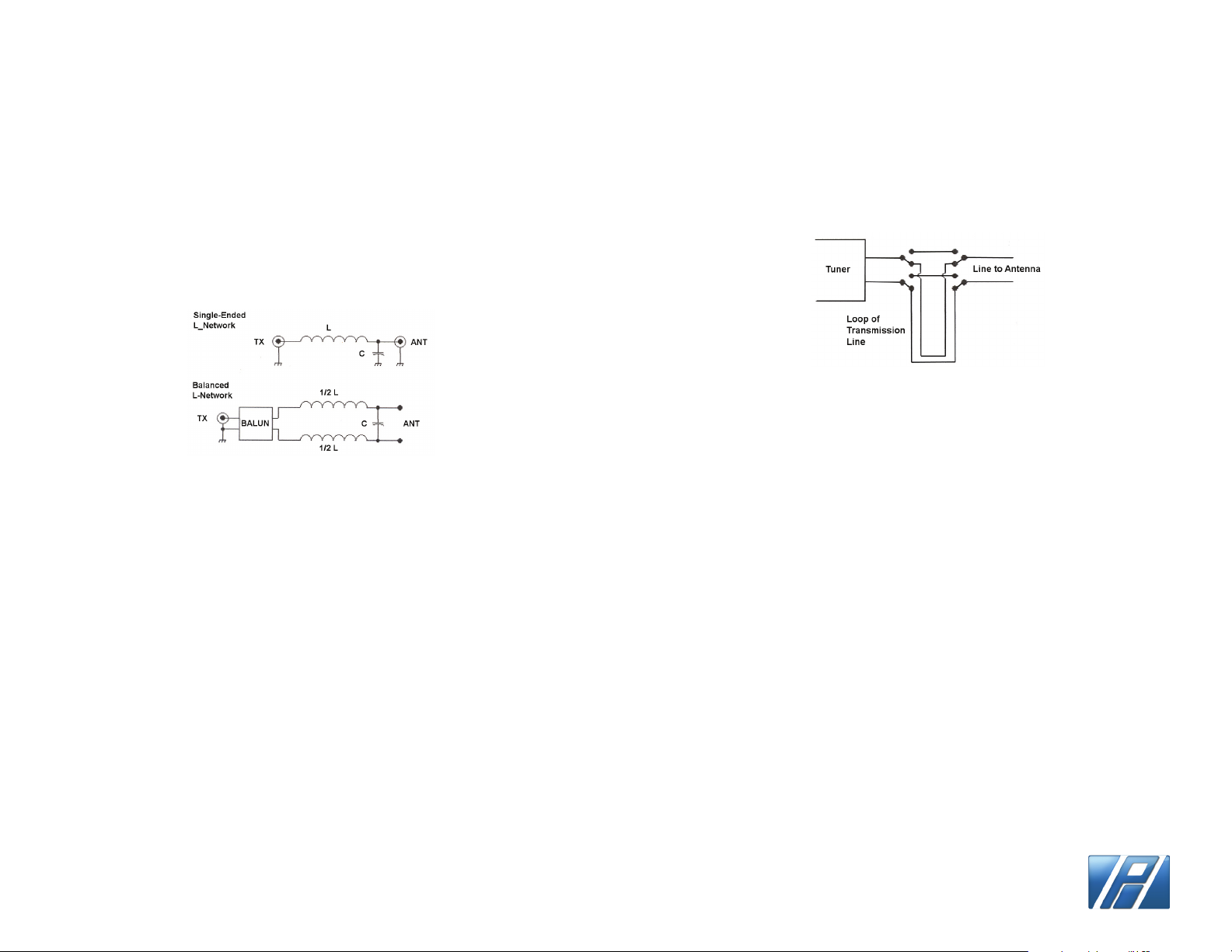
transmitter, the tuner places a 1:1 choke (current) balun between
the input side of the network and the transmitter coax connector.
The balun converts the unbalanced input from the transmitter to
a balanced condition for the network. As well, it suppresses
currents that might otherwise appear on the braid of the
transmitter cable.
Limitations: Every antenna tuner, no matter what the type, has
limits to the range of impedances that it will match to the 50 Ohm
input. The balanced L-network is no exception. Understanding
those limitations will help you to eect a match on every band.
The impedance presented to the tuner antenna terminals is usually
expressed as a series combination of resistance and reactance, that
is, R +/-jZ Ohms. The L-network that places its shunt capacitor on
the antenna side is normally an up converter. The limiting lower
end impedance is in the vicinity of 60 to 100 Ohms resistive for a
50 Ohm input. The upper limit of impedance that the network will
match is a complex function of frequency, the component values,
and the amount of reactance that is part of the impedance at the
tuner terminals. For most of the HF Amateur bands, the upper
impedance limit of the balanced L-network in the Palstar BT1500A
tuner is about 2500 +/- j2500 Ohms. This upper limit descends
slowly with rising frequency so that at 30 MHz the upper limit is
about 400 +/- j400 Ohms. The decrease in range results from the
unavoidable minimum capacitance of the output variable
capacitor.
The impedance presented to the antenna terminals may be any
value of R and any valye of X. For a given R component, the tuner
will require a certain setting of the coil and also the capacitor. If
there is reactance at the antenna terminals, then the network
requires a lower value of C if the reactance is capacitive, and a
higher value of C if the reactance is inductive. The network
compensates for the reactance by increasing or reducing the
capacitive reactance required for a purely resisitive load with only
small changes in the required inductance. The amount of
compensation available is a function of the maximum and minimum
values of shunt capacitance and the resulting reactance of this
component. With nite components, the range of reactance for
which the network can compensate is always limited.
As well, every matching network incurs losses within the network,
mostly as a function of the Q of the inductor and the ratio of the
antenna terminal impedance to the input impedance. For the
balanced L-network with a shunt output capacitor,
the higher the impedance to be matched, the higher
the losses. The losses will be lower if the reactance
at the antenna terminals is purely resistive.