Denray 3444B Super User manual

OPERATING INSTRUCTIONS
Mini Booth
WARRANTY
This Machine is covered with a 12 month warranty. The warranty covers replacement parts, except filters
and wooden top (if applicable). The only way Denray will cover the labor is the work must be done by
Denray at Denray's Facility. The shipping must be provided by the customer (owner of the machine) both
ways. You may contact the dealer you purchased the machine from, and discuss with them, the
possibility of their assistance in helping to solve the problem in your facility. Denray assumes or accepts
no responsibility more than the cost of the machine. In the case of repair Denray will determine either to
fix or replace the product. Denray reserves the right to modify or change the design of this and any model
of their machines, without changing or updating any previous manufactured machine.
The warranty will not cover any damage done by fire or any other act of nature or if abuse or improper
maintenance was or was not performed.
To find YOUR tables pertinent information please locate the table sticker on your table.
**Please note the image above is a "generic" table sticker for visual purposes only! The table sticker
on your machine reflects how it left the manufacturer and does not reflect any after-market changes
made by previous owners. If you have questions please call Denray Machine at (800) 766-8263.
Never Allow Any Unauthorized or Untrained Person To Operate This
Machine
Lockout and tagout any time maintenance is performed on this
machine
WARNING
NEVER GRIND OR SAND ANY ALUMINUM OR MAGNESIUM, OR ANY
SPARK CREATING PRODUCT ON THIS MACHINE
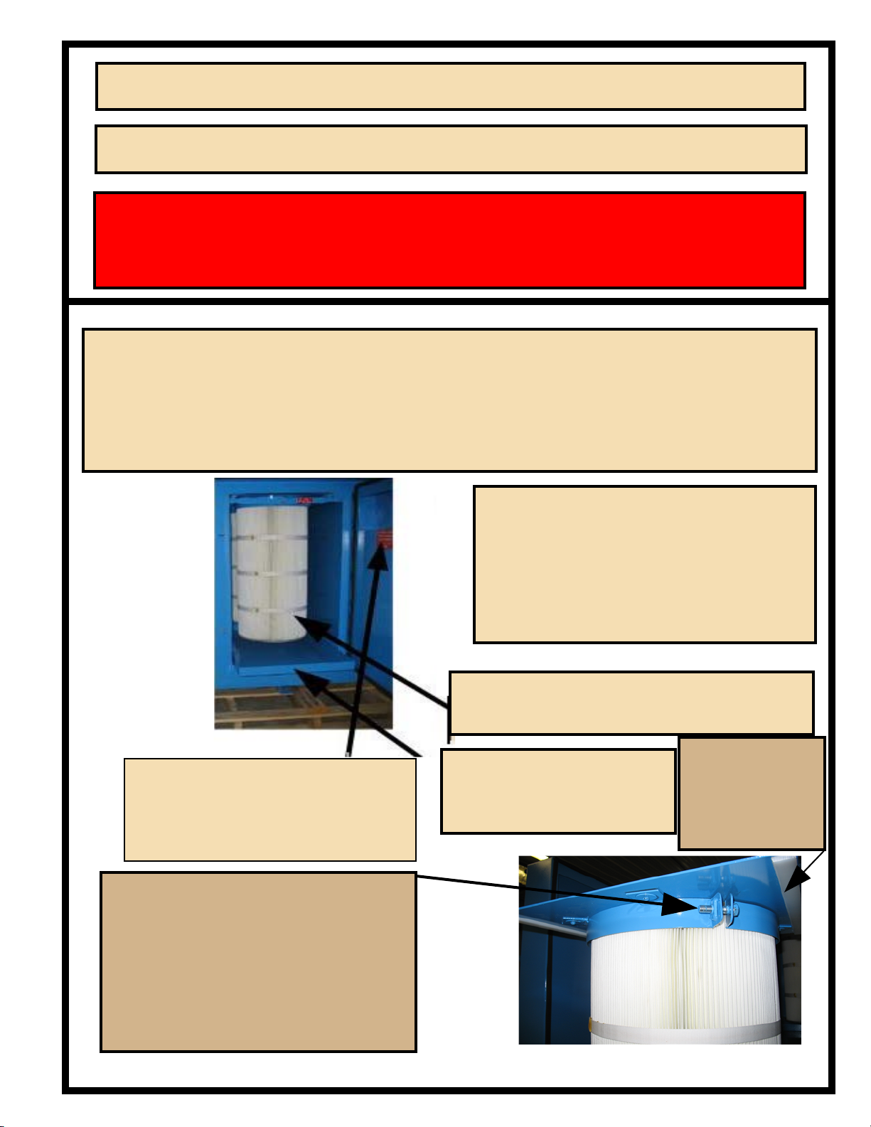
Filters are the main need of maintenance, the cleaner the filters are kept the better the machine will
perform. This machine is equipped with timers to clean the filters, every so many minutes a pulse of
air will be released into one of the filters, and a few minutes later the other filter will be pulsed, the
time is needed to refill the tank. The time between pulses are adjustable, refer to the electrical
diagram. Warning if the time is reduced between pulses the filter may plug up reducing the
machines performance. The filters can also be pulsed with the machine off, it may blow dust back
into the work area, so caution should be used here, pulse the machine then turn machine on to pull
dust back into the filters.
The filters will clean better with machine off,
you may shut machine off and before it slows
down to a complete stop, pulse the filter and
allow the fan to prevent the dust from exiting
the filter compartment.
Filter replacement number is on the inside of
the filter door.Be sure to replace with same
type of filter or a filter made of polyester
media.
Bolt that holds the band that
secures the filter to the steel plate
that slides in the filter unit.
This makes removing filters from
the plate very easy, Allowing filter
deep cleaning a much easier task,
thus allowing the filters
to be cleaned better and easier.
Filter replacement number
Is on inside of this door.
MUST replace with the
prop
er fire retardant filter
Cartridge Filters 99.95% efficeincy
down to .5 micron
Dust Drawer Clean
regularly, as needed
UMHW Plastic
strips for ease
of sliding the
filters. Must be
in place
This Vee will align into the filter
placed in first
Never Open Any Door
While Machine Is Running
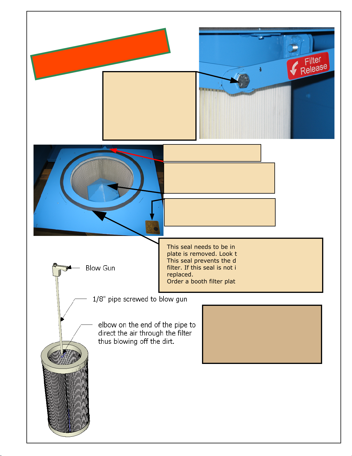
This bolt holds the
levers that raise and lowers
the filters. Once the machine
is in place, remove the nut
from this bolt, once the
bolt is in the hole pull down
on the levers to lock the
bolt in place.
looks like the picture
The cone on the inside of the filters
enhances the cleaning process. It is
bolted into the bottom of the filter.
This shows the location of the four
filters, the black circle shows this
filter is the front right filter.
This seal needs to be inspected everytime the steel
plate is removed. Look to see if any missing rubber,
This seal prevents the dust from by passing the
filter. If this seal is not intact it needs to be
replaced.
Order a booth filter plate seal
Harbor Freight Catalog outlet
sells a blow gun with a long
stem that will reach into all
the filters.
Filter Cleaning is almost the only thing
that has to be done to maintain these
machines. No lubrication to maintain
The cleaner the filters are kept the
better the machine will perform.
The dirtier the filters the harder it is
to pull air through them.
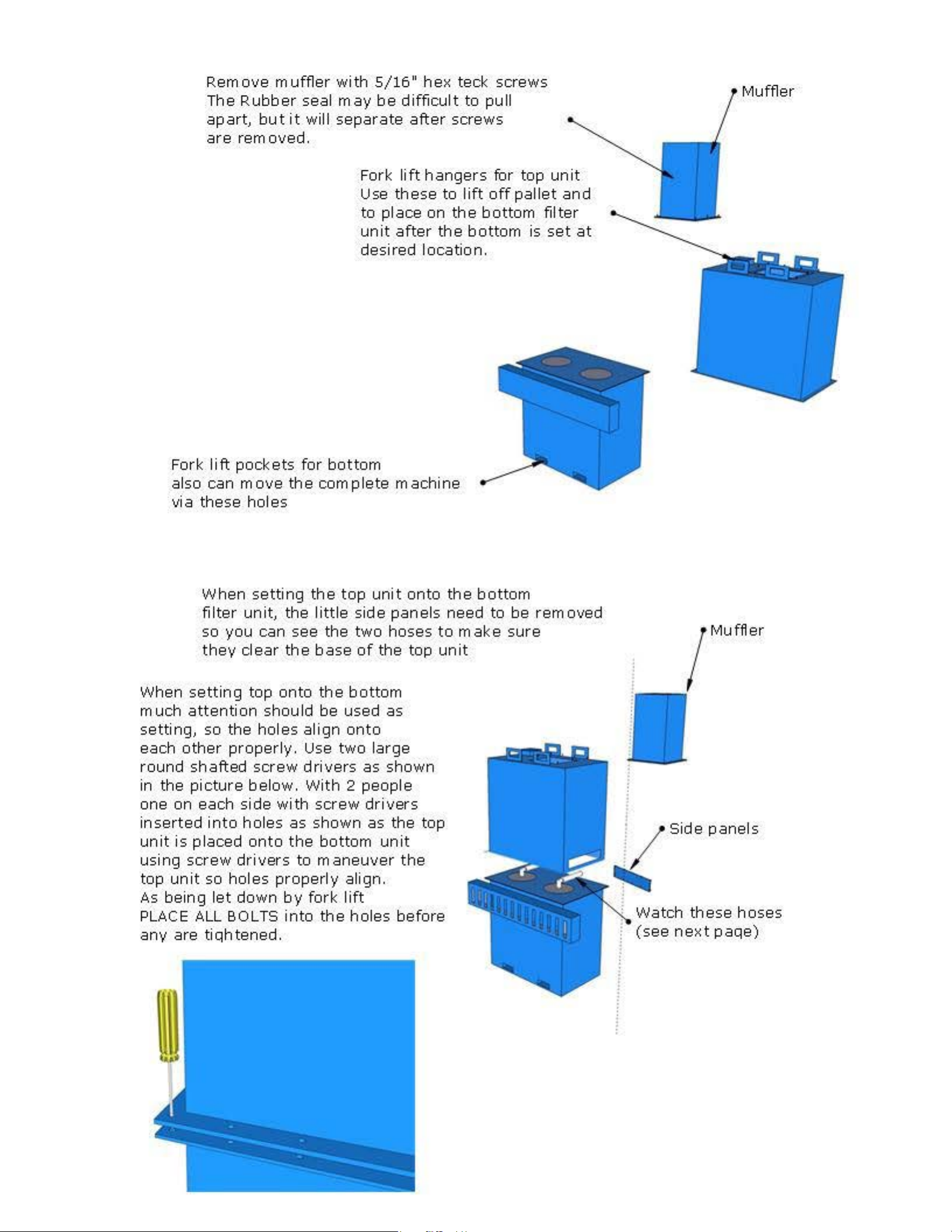
Rem
ave
muffler
with
5/16"
hex
teck screws
The
Rubber
seal
may
be
difficult
to
pu
II
apart,
but
it
wilI separate
after
screws
are
removed.
Fork
Ii
ft
hangers
for top
unit
Use
these
to
I
ift
off
pal
let
and
to
place on
the
bottom
filter
unit
after
the
bottom
is
set
at
desired Iocation.
Fork
lift
pockets
for
bottom
also can m
ave
the
complete
machine
vi
a these holes
When
setting
the
top
unit
onto
the
bottom
filter
unit,
the I
ittle
side panels need to be
removed
so you can see the
two
hoses
to
make
sure
they
cl
ear
the base
of
the top
unit
When
setting
top onto the
bottom
much
attention
shou
Id
be used as
setting, so the holes align
onto
each
other
properly.
Use
two
large
round shafted
screw
drivers
as shown
in the
picture
below. With 2 people
one on each side
with
screw
drivers
inserted
into
holes as shown as the top
unit
is
placed
onto
the
bottom
unit
using
screw
drivers
to
maneuver
the
top
unit
so holes
properly
align.
As
being
let
down
by
fork
I
ift
PLACE
ALL
BOLTS
into
the
holes before
any
are
ti
qhtened.
/
Muffler
kSide panels
Watch
these
hoses
(see
next
paqe)

The
two
sides
are
to
be
mounted
to
the
unit
Muffler
to
be
mounted
and
screwed
on
Now
the top
bracket
paqe
3

On each end
/side
there
is a
sm
alI panel
held on
with
the
5/16"
hex
headed screws
that
opens
to
the
hoses th
at
leads
to
the
air tank, remave the panel and you
wi
II
see
the
hose
that
fits on the hosebib.
placing
the
hose
over
the bib and tightening
the
hose clamp
to
secure the hose, so
the
filters
can be pulsed cleaned.
hose
not
on
Hose placed
over
the bib
and
the clamp
in
place.

Top is
in
location
now
the
sides
are
ready
to
Iocate and place
left
side
.
.
.
.
iri
to
position
'
'
.
Riqht
side
Weld on
hinge
is
what
secures
the
sides,
just
slide
the pin in
to
the hole. Lubrication
Ii
ke
WD
40
wilI help
all
ow
the
side
to
slide
into
hole
better.
left
side
Top coming in
next
after
sides are
into
place.
Riqht side
.
'
.
'
'
•
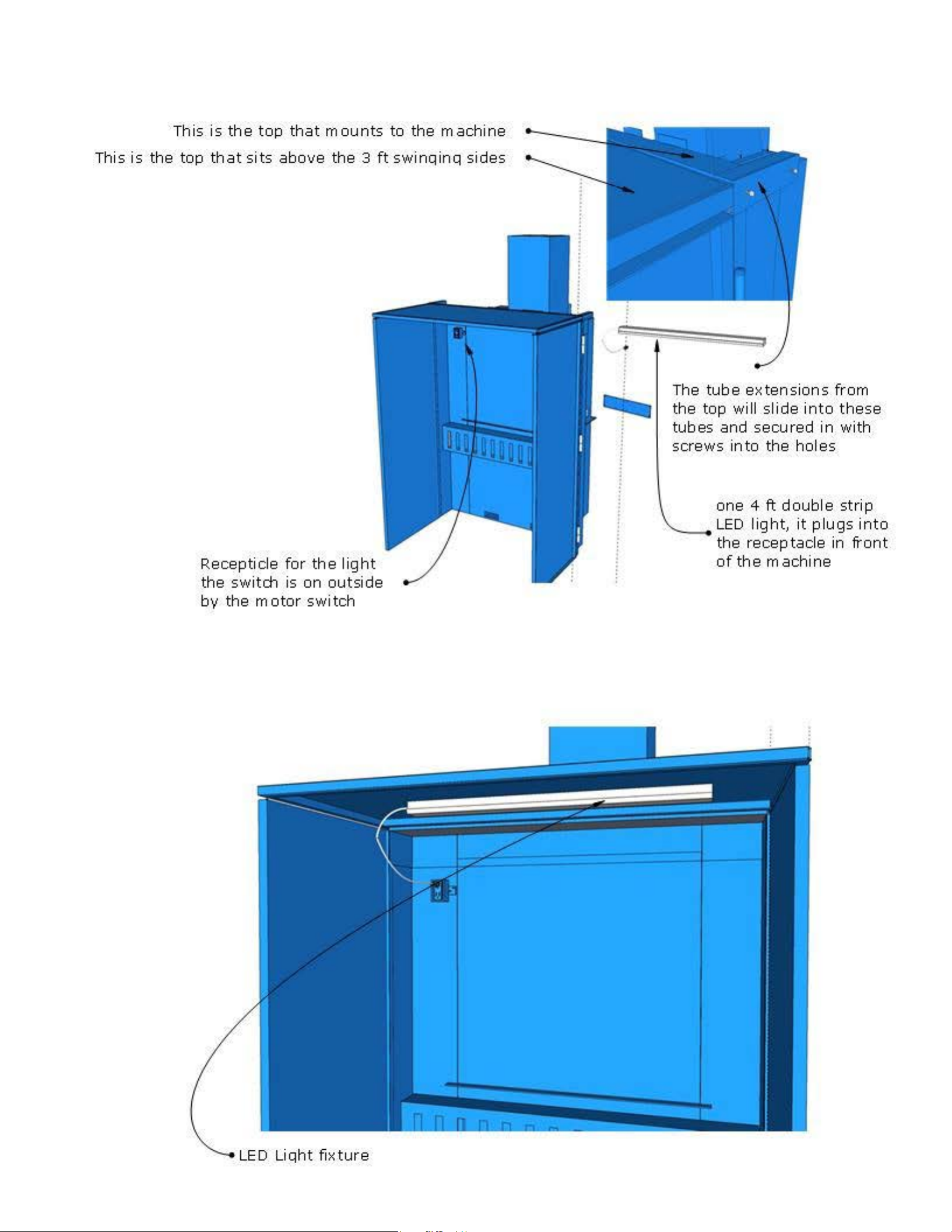
Th
is
is
the top
that
mounts
to
the
machine
This
is
the top
th
at
sits above the 3
ft
swinqinq sides
Recepticle
for
the Iig
ht
the switch is on outside
by
the
motor
switch
LED
Li
qht
fixture
'
,::::
•
'
'
=
The
tube
extensions
from
the top wi
II
slide
into
these
tub
es
and secured
in
with
screws in
to
the holes
one 4 ft
double
strip
...__
LED
Iig
ht,
it
plugs
into
the receptacle in
rront
of
them
achine
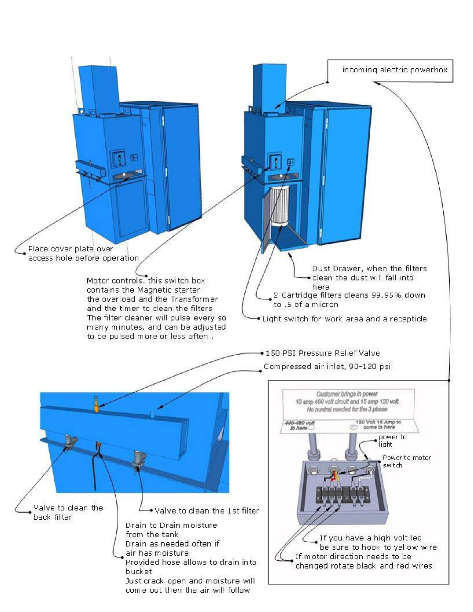
Place
cover
pl
ate
\
over
.
access
hole
befo
re
operation
incom inq electric
powerbox
\
Dust
Drawer,
when
the
filters
L clean the du
st
wi
II
falI
into
here
Motor
controls.
this
switch
box
contains
the
Magnetic
starter
the
overload
and the Transform
er
and
the
timer
to
clean
the
filters
The
filter
clean
er
wilI pulse
every
so
many
minutes,
and can
be
adjusted
to
be pulsed
more
or
less
often
.
.___2
Cartridge
filters
cleans
99.
95%
down
to
.5
of
am
icron
Valve
to
clean the
- - back
fi
I
ter
----
Li
qht
switch
for work
area
and
a recepticle
.----
---150
PSI Pressure
Relief
Valve
com
pressed
air
inlet,
9
0-120
psi
------
-
Valve
to
clean
the
1st
filter
Drain
to
Drain
moisture
from the
tank
Drain
as
needed
often
if
air
has
moisture
Provided hose allows
to
drain
in
to
bucket
Ju
st
erack open and
moisture
wi
11
come
out
th
en the
air
wilI follow
Cudomarblfngan
powi;r
10
_,.,
WI
Vil/I
c/mil
and
16
IJITfJ
12/J
Vil/I.
Ho-...,Jedfortho3pt,-
12i0Voi11M,jto
<D
oom,ef,\
,-.
power
to
,,-
-lioht
If
you
have
a
high
volt
leg
be sure
to
hoak
to
yellow
wire
If
motor
direction
needs
to
be
,___,
_ chanqed
rotate
black and
red
wires
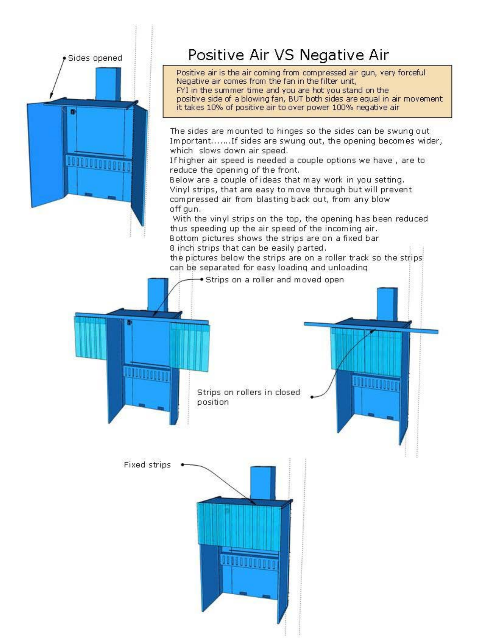
Si
des opened Positive Air VS Negative Air
Positive air is the air coming
from
compressed air gun, very forceful
Negative air
comes
from the fan in thefilter unit,
FYI
in the summer time
and
you
are hot you stand
on
the
positive side of a blowingfan,
BUT
both sides are equal in air movement
it takes 10%
of
positive air
to
over power 100% negative air
The sides are
mounted
to
hinges so the sides can be swung
out
Important.
......
If
sides
are
swung
out,
the
opening becomes wider,
which slows down
air
speed.
If
high
er
air speed is needed a couple
options
we have ,
are
to
reduce the opening
of
the
front.
Bel
ow
are
a coupie
of
ideas
that
may
work
in
you setting.
Vinyl strips,
that
are easy
tom
ave through
but
will
prevent
com pressed air rrom blasting back
out,
from
any
blow
off
gun.
With the vinyl
strips
on the top, the opening
has
been reduced
th
us speeding up
the
air
speed
of
the incoming air.
Bo.
ttom
pictures shows the
strips
are
on
a fixed
bar
B ihc
ti
strips
that
can be easily
parted.
:
th
e
pi
'ctures below
the
strips
are on a
roller
track so
the
st
~ips:
can b~ separated
for
easy Ioadinq
and
unloadinq ,
· ' Strips on a ro
II
er
and
moved
open '
Fixed
strips
Strips on rollers
in
closed
position

,0q{Alrolcid*',dlS@rfrril-
,&ffitffituilDgPrE
Fco-nlrruceowe!
Fu$'l&2$oteds
th€ tBsftrffi and
tu* 3 prdeds the
Overload dial sd
just above motor
And Two \falves
Boxon top
of machine
120 Volt in here
44G4B0Volt 3PH in here
'l'ie red into orle valve
Tie Uue into other vah,e
rnake sure the wire frorn
tlle tirnerand the rnanual
$r/itch are both positive
Valve 1
On two valves bring
nuetral from one to the other
--oY*:
Light Switch
Valve 2
Generalsettings
\ bod taBs 24 minutes
Grind taHes 18 minutes
\ Hd srnoketab[es 12 minutes
s=sorin-----\ u$o-;ffi*n setHerefor6$omin.
6=36min -\ r-ro.iKa-3r-ron
Ii3ffi gg-*"*-*ffi;=
9-54min 7-.q- \s_^
1o+omin \ffi_--i "

TROUBLE SHOOTING
Motor not running Look to see if L1- L2 -L3
wires are in and secured
and proper voltage is there
Check if wires at bottom of
mag starter to the motor are
in bottom and secured.
The above checks OK In center of the contactor is a rectangle post that is
hooked to coil below. With screwdriver push in and see
if motor will run. If motor will run something is wrong
with the push buttons, That activates the starter.
Motor runs when center
post is held in, but not
by the switches
Make sure every wire is secured on starter if
still no results call Denray for further assistance
If center post is held in
and nothing happens
hook power leads to motor
leads at bottom of mag
starter if motor runs the
problem is the starter.
Call factory for switch replacement
If on switch closes mag
starter and motor does
not run.
FIRST take tester and check see if there is the
proper voltage at bottom of starter
If proper voltage is at
bottom of starter Check to see wiring at motor is properly
hooked together
All the below solutions are meant to be done
only by a qualified technician
Mag starter works
and motor only hums Check for proper voltage
check all wire connections to be tight
check wiring diagram and motor leads to be correct
Filter Cleaning valve will
not pulse Check the three 1 amp fuses on
top of the transformer in the
switch box.
Fuses OK Check wiring in front of and behind the fuses
Fuses and wiring checks
out OK With it being quiet activate the switch and listen
to hear a clicking sound from the valve or valves.
You hear it clicking Make sure air is hooked up to tank
Air is hooked up
and it still clicks Call Denray Replace valve
1
2
3
4
5
6
7
8
9
10
11
12
Motor runs for a
few minutes and
shuts off
Turn the amp dial on overload to increase the
number. Increase only 1 amp at a time
Never increase more than 2 amps above motor
full load amps
13

TROUBLE SHOOTING
Loss of suction on top
of table Dirty filters :: Refer to above
All the below solutions are meant to be done
only by a qualified technician
Excessive exhaust air
on the floor
Rotate filters two times a week 1/4 turn
Timer not working
Machines with timers Check fuses:: Check wiring between mag starter
and timer. Any loose connection,
secure the connection
Filters need to be
cleaned more often Turn dial on timer to a lesser number set at
factory at approx. every 20 minutes.
Lots of dirt remaining on
filters after being cleaned Decrease time between cleanings. Check air
pressure going into machine.
Keep between 100-140 psi
Filter never completely
cleans all dirt off Not supposed to:: Machine designed to operate at
30% filter blockage. The cleaner a filter is the better
the machine will perform.
Any air that is sucked into the table top must come
out in exhaust somewhere. Look into adding Muffler
to machine
Dirt packed in top 1/3 of
filters
Inside of filters are
rusty colored Blowing water from air tank inside of filter. Drain
air tank more often ( daily if possible) Installation
of a dryer or water trap may be necessary
Filters will not come
clean Pull filters out of machine and take blow gun and
from inside blowing out give filters a deep cleaning
How often do I need
to do the above Some companies do it daily and some weekly
and some monthly. You must determine that
for yourself
Moisture blowed in filters
will make filters harder
to clean
14
15
16
17
18
19
20
21
22
23
24
25
26
Refer to 22
Are filters washable? Spun-bond filters in the grind tables can be washed only
a couple times and must let thoroughly dry.
Filter cleaning service companies may be available in
your area.
Green light on timer
does not work See above
Bad timer needs replacement

All fans are factory balanced from fan company,
fans checked and rebalanced at table MFG, if
table has vibration, fan weights may need to be
moved to another blade.
TROUBLE SHOOTING
All the below solutions are meant to be done
only by a qualified technician
27
28
29
Fan making a loud roar Fan rotation backwards, on three phase,switch
wires on L1 and L2
Lack of proper suction Fan running backwards will produce 2/3rds less
suction check fan rotation
See Drawing Fan
Rotation
Machine vibration on
direct drive systems
Other manuals for 3444B Super
1
This manual suits for next models
1
Table of contents
Other Denray Industrial Equipment manuals


Popular Industrial Equipment manuals by other brands


Noble House Home Furnishings
Noble House Home Furnishings Chair Assembly instructions

ABB
ABB HT613135 Operation manual

Venmar
Venmar K7 ERV User's and installer's manual

GRUNDFOS ALLDOS
GRUNDFOS ALLDOS Oxiperm C 164 Series Operation and service manual

ABB
ABB HT604072 Operation manual

Neopost
Neopost RENA XPS-ProMail 3.0 user guide