Denso BA20-RU User manual

Bluetooth®Adapter
BA20-RU
User’s Manual

Copyright © DENSO WAVE INCORPORATED, 2015
All rights reserved. No part of this publication may be reproduced in any form or by any means without permission in
writing from the publisher.
QBdirect®are trademaks of DENSO WAVE INCORPORATED. Microsoft Windows®is a trademark of
Microsoft Corporation. Bluetooth®is a trademark of Bluetooth SIG. Other products and company names mentioned in
this document are trademarks or registered trademarks of their respective holders.
Specifications are subject to change without prior notice.

Contents
Preface ........................................................................................................................................................ i
Customer Registration and Inquiries.......................................................................................................... i
SAFETY PRECAUTIONS ....................................................................................................................... ii
Bluetooth®Wireless Communication Link............................................................................................... v
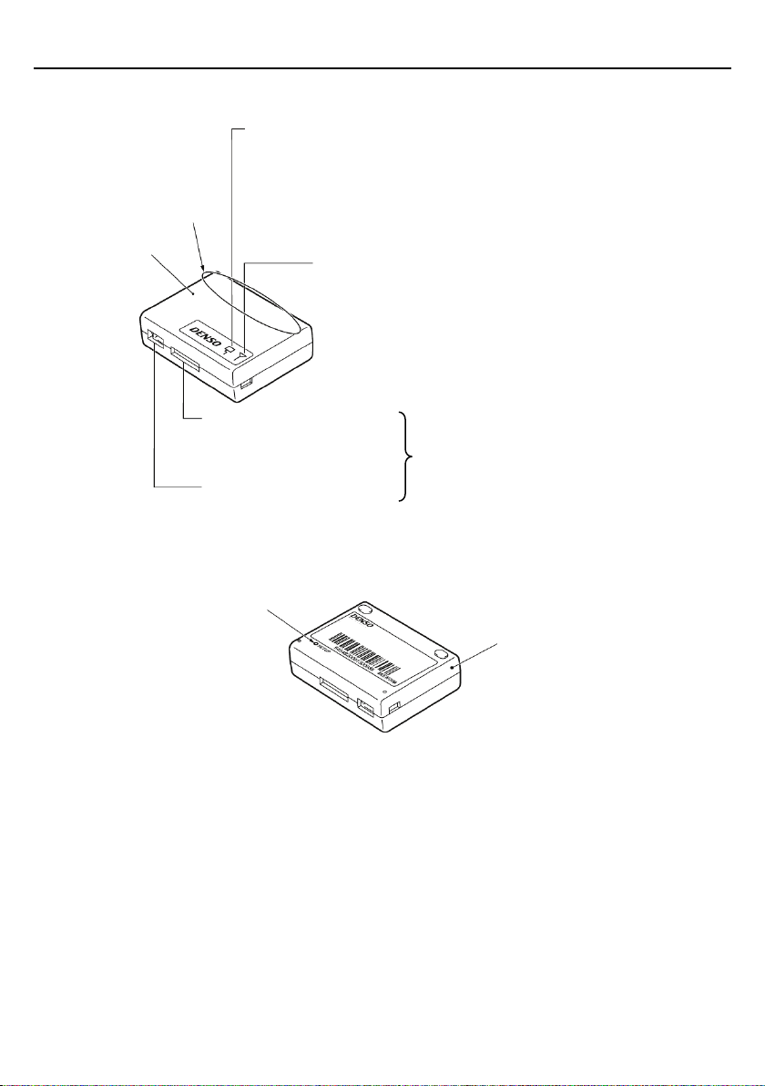
Chapter 1 Part Names and Functions ..................................................................................................... 1
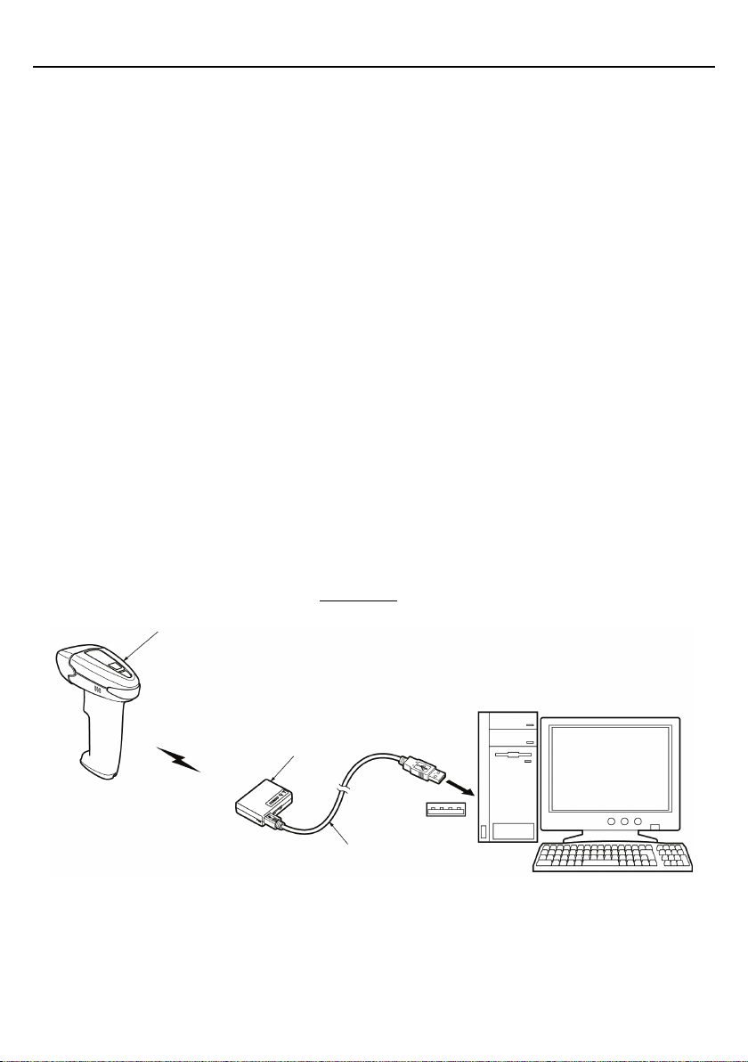
Chapter 2 Connection to the Host Computer ......................................................................................... 2
2.1 Location of the Bluetooth®Adapter..................................................................................... 2
2.2 Connection between Interface Cable and Bluetooth®Adapter............................................ 2
2.3 Using USB Interface ............................................................................................................ 2
2.3.1 Operating environment ............................................................................................... 3
2.3.2 Notes for connecting the USB interface cable............................................................ 3
2.3.3 Setting up the USB interface....................................................................................... 4
2.4 Using RS-232C Interface ..................................................................................................... 6
Chapter 3 BluetoothWireless Communication ................................................................................... 8
3.1 Establishing BluetoothWireless Link ............................................................................... 8
3.2 Indication of Bluetooth interface cable................................................................................ 9
Chapter 4 Customizing the Bluetooth®Adapter .................................................................................. 10
Chapter 5 Communication ................................................................................................................... 11
5.1 Bluetooth®.Interface ........................................................................................................... 11
5.2 Interfacing with the Host.................................................................................................... 12
5.2.1 USB keyboard interface ............................................................................................ 12
5.2.2 USB-COM interface.................................................................................................. 12
5.2.3 RS-232C interface ..................................................................................................... 13
5.3 Data Transmission Format Selections ............................................................................... 14
5.4 Data Packaging (Packetizing) ............................................................................................ 15
Chapter 6 Parameters and Defaults ...................................................................................................... 16
Chapter 7 Troubleshooting................................................................................................................... 21
Appendix 1 Specifications ................................................................................................................... 22
Appendix 2 BluetoothGlossary ......................................................................................................... 23
Appendix 3 Pairing (Device authentication)........................................................................................ 24

Preface
Thank you for using the BA20-RU DENSO WAVE Bluetooth®adapter.
Please READ through this manual carefully. It will enable you to use the Bluetooth®adapter BA20-RU correctly.
After you have finished reading this manual, keep it handy for speedy reference.
Note: Do not use this scanner in an environment with electrical noise that can trigger malfunction.
Note: Specifications described in this manual are supported by BA20-RU Firmware version 1.00 or later.
DENSO WAVE INCORPORATED does not assume any product liability arising out of, or in connection with, the
application or use of any product, circuit, or application described herein.
If it is judged by DENSO WAVE INCORPORATED that malfunction of the product is due to the product having
been dropped or subjected to impact, repairs will be made at a reasonable charge even within the warranty period.
Intellectual Property Precaution
DENSO WAVE INCORPORATED ("DENSO WAVE") takes reasonable precautions to ensure its products do not
infringe upon any patent of other intellectual property rights of other(s), but DENSO WAVE cannot be responsible
for any patent or other intellectual property right infringement(s) or violation(s) which arise from (i) the use of
DENSO WAVE's product(s) in connection or in combination with other component(s), product(s), data processing
system(s) or equipment or software not supplied from DENSO WAVE; (ii) the use of DENSO WAVE's products in
a manner for which the same were not intended nor designed; or (iii) any modification of DENSO WAVE's products
by other(s) than DENSO WAVE.
Customer Registration and Inquiries
Customer Registration
To allow us to provide our customers with comprehensive service and support, we request that all customers complete
a Member Registration Form. Registered members will be offered the following privileges.
•Latest upgrade information
•Free exhibition and event information for new products
•Free web-information service "QBdirect"
QBdirect Service Contents
Information search
service (FAQ)
Offers detailed information on each product.
Download service Offers downloads of repair modules for the latest BA20-RU Series systems or
software, and sample programs.
E-mail inquiries Allows customers to send product-related queries by e-mail.
Please note that these privileges may be subject to change without prior notice.
How to Register
Access the URL below and follow the instructions provided.
http://www.qbdirect.net
i

SAFETY PRECAUTIONS
Be sure to observe all these safety precautions.
Please READ through these instructions carefully. They will enable you to use the Bluetooth®adapter BA20-RU
correctly.
Always keep this manual nearby for speedy reference.
Strict observance of these warning and caution indications is a MUST for preventing accidents which could result in
bodily injury and substantial property damage. Make sure you fully understand all definitions of these terms and
related symbols given below, before you proceed on to the text itself.
Alerts you to those conditions which could cause serious
bodily injury or death if the
instructions are not followed correctly.
Alerts you to those conditions which could cause minor bodily injury or substantial
property damage if the instructions are not followed correctly.
Meaning of Symbols
A triangle ( ) with a picture inside alerts you to a warning of danger. Here you see the warning for
electrical shock.
A diagonal line through a circle ( ) alerts you to something you should not do; it may or may not have a
picture inside. Here you see a
screwdriver inside the circle, meaning that you should not disassemble.
A black circle ( ) with a picture inside alerts you to something you MUST do. This example shows that
you MUST unplug the power cord.
ii

To System Designers:
•When introducing the Bluetooth®adapter in those systems that could affect human lives (e.g.,
medicines management system), develop applications carefully through redundancy and safety
design which avoids the feasibility of affecting human lives even if a data error occurs.
•When using the RS-232C interface, use the dedicated AC adapter only.
Failure to do so could result in fire.
•If the interface cable or AC adapter cable (if connected) is damaged, e.g., exposed or broken lead
wires, stop using it and contact your nearest dealer.
Failure to do so could result in a fire or electrical shock.
•Never bring any metals into contact with the terminals in connectors.
Doing so could produce a large current through the Bluetooth®adapter, resulting in heat or fire, as
well as damage to the Bluetooth®adapter.
•Never use the Bluetooth®adapter on the line voltage other than the specified level.
Doing so could cause the Bluetooth®adapter to break or burn.
•Do not use the Bluetooth®adapter where any inflammable gases may be emitted.
Doing so could cause fire.
•Keep the AC adapter away from water.
Failure to do so could cause fire or electrical shock.
•Do not scratch, modify, bend, twist, pull, or heat the interface cable or AC adapter cable (if
connected). Do not place heavy material on it or allow it to get pressed under heavy material.
Doing so could break cables, resulting in a fire.
•If smoke, abnormal odors or noises come from the Bluetooth®adapter, immediately switch off the
host PC, unplug the AC adapter (if connected) from the electrical outlet and the interface cable from
the host PC, and contact your nearest dealer.
Failure to do so could cause fire or electrical shock.
•If foreign material or water gets into the Bluetooth®adapter, immediately unplug the AC adapter (if
connected) from the electrical outlet and the interface cable from the host PC, and contact your
nearest dealer.
Failure to do so could cause fire or electrical shock.
•If you drop the Bluetooth®adapter so as to affect the operation or damage its housing, switch off the
host PC, unplug the AC adapter (if connected) and the interface cable, and contact your nearest
dealer.
Failure to do so could cause fire or electrical shock.
iii

Never
disassemble
•Never disassemble or modify the Bluetooth®adapter; doing so could result in an accident such as
break or fire.
Doing so could result in a fire or electrical shock.
•Do not put the Bluetooth®adapter on an unstable or inclined plane.
The Bluetooth®adapter may drop, creating injuries.
•Never put the Bluetooth®adapter in places where there are excessively high temperatures, such as
inside closed-up automobiles, or in places exposed to direct sunlight.
Doing so could affect the housing or parts, resulting in a fire.
•Avoid using the Bluetooth®adapter in extremely humid areas, or where there are drastic
temperature changes.
Moisture will get into the Bluetooth®adapter, resulting in malfunction, fire or electrical shock.
•Do not place the Bluetooth®adapter anyplace where it may be subjected to oily smoke or steam,
e.g., near a cooking range or humidifier.
Doing so could result in a fire or electrical shock.
•Never cover or wrap up the Bluetooth®adapter or AC adapter in a cloth or blanket.
Doing so could cause the unit to heat up inside, deforming its housing, resulting in a fire.
Always use the Bluetooth®adapter and AC adapter in a well-ventilated area.
•Keep the AC adapter cable away from any heating equipment.
Failure to do so could melt the sheathing, resulting in a fire or electrical shock.
•Do not insert or drop foreign materials such as metals or anything inflammable through the openings
or vents into the Bluetooth®adapter.
Doing so could result in a fire or electrical shock.
•Do not scratch or modify the Bluetooth®adapter or its interface cable. Do not bend, twist, pull, or
heat the cable.
Doing so could damage the Bluetooth®adapter or its interface cable, creating a fire hazard.
•Do not use the Bluetooth®adapter if your hands are wet or damp.
Doing so could result in an electrical shock.
•Never use chemicals or organic solvents such as benzene and thinner to clean the housing. Do not
apply insecticide to the Bluetooth®adapter.
Doing so could result in a marred or cracked housing, electrical shock or fire.
•Do not use the Bluetooth®adapter with anti-slip gloves containing plasticizer.
The Bluetooth®adapter housing may be broken, creating injuries, electrical shock, or fire.
iv

Bluetooth®Wireless Communication Link
The Bluetooth®adapter BA20-RU uses Bluetooth®wireless networking technology.
Item Specifications
Standard Bluetooth
®
Specification Ver. 2.1 + EDR
Radio output Class 2 (maximum 2.5 mW)
Profile(s) supported Serial port profile
Communications range (reference value*1) Max. 10 m, with no obstructions
*1 This is a value for the communication between the Bluetooth®adapter and the DENSO WAVE wireless scanner.
Communication range varies depending on the device to communicate with and operating environment.
Wireless networking requires a stable radio environment. Not all operating environments provide this. In particular,
note that
•Using the Bluetooth®adapter in close proximity to other wireless LAN equipment operating in the same frequency
band (2.4 GHz) risks radio interference that can reduce throughput or even entirely block wireless networking.
•Microwave ovens, industrial heating equipment, high-frequency medical equipment, and other equipment using the
2.4 GHz band can sometimes block wireless networking.
•Electromagnetic noise from computers, refrigerators, and other home appliances can sometimes block wireless
networking.
•The following environments can sometimes block wireless networking.
- Metal objects or particles in the vicinity
- Metal walls around the area
- Excessive vibration
•The communications range of 10 m given above is merely a reference value assuming a clear line of sight. Reliable
wireless networking is by no means guaranteed at 10 m for all combinations of equipment used and operating
environments. Some combinations might even work for greater distances, but be sure to confirm that the Bluetooth®
adapter link operates properly before introducing the link operation.
NOTE:
To System Designers:
•
Before developing applications, make sure that the intended environment is free
of the interference factors
above and thus actually capable of supporting link operation.
•
When introducing the Bluetooth®adapter into an environment where equipment
using radio waves in the
2.4 GHz band operates or when introducing such equipment after the introduction of the Bluetooth
®
adapter, be sure to confirm that the adapter
radio link operates properly with all equipment being in
operation beforehand.
•
If the environment of the radio communications system is changed after the
introduction (e.g., newly
installed household appliances and movement/addition of
shelves or objects), then confirm that the radio
link operates properly again before the actual use.
v

Chapter 1 Part Names and Functions
Bluetooth®adapter
Interface/power supply LED
For the first two seconds after the power is first applied, the color indicates the
interface setting.
-
Orange: USB interface
-
Red: RS-232C interface
After that, the LED is green to indicate that the
adapter has power.
(Refer to Chapter 3 for details.)
Bluetooth®
status display LED (blue)
This lights or blinks to indicate the current Bluetooth
®wireless
link status.
(Refer to Chapter 3 for details.)
USB interface connector
RS-232C interface connector
Interface connectors
The unit uses these to exchange data with the
host computer or similar communications
device.
(Refer to Chapter 2 for details.)
Bluetooth®adapter (rear)
SETUP button
Pressing this button initiates
parameter specification for the
Bluetooth
®adapter.
(Refer to Chapter 4 for details.)
Built-in antenna
Bluetooth
®antenna.
Do not
modify this
antenna section or cover it
by hand.
1

Chapter 2 Connection to the Host Computer
The Bluetooth®adapter connects to the host computer via any of the following three interfaces.
•USB keyboard interface (default)* (See Section 2.3)
•USB-COM interface (See Section 2.3)
•RS-232C interface (See Section 2.4)
Note: Using a USB keyboard interface requires selecting the keyboard type that matches the one at the host computer
with the configuration software “BA Setting”. Using any other interface requires changing the Bluetooth®adapter
settings also with the configuration software. In any case using the configuration software, it is necessary to use a
USB-COM interface (See Section 2.3) or RS-232C interface (See Section 2.4) to the host.
2.1 Location of the Bluetooth®Adapter
Locate the Bluetooth®adapter, observing the following notes in order to secure the wireless link between the
Bluetooth®adapter and the scanner.
- Do not locate the Bluetooth®adapter on a metallic desk or wall. If it is unavoidable, keep the Bluetooth®adapter
away at least 15 cm (5.9") from the metallic surface.
- Make sure that there is no metallic obstruction in the wireless path between the Bluetooth®adapter and the scanner.
2.2 Connection between Interface Cable and Bluetooth®Adapter
Connect the desired interface cable to the corresponding interface connector provided on the side of the Bluetooth®
adapter.
Note: Hold the Bluetooth®adapter, align the adapter's connector and interface cable connector with each other, and
fully insert the interface cable into the adapter's connector.
2.3 Using USB Interface
Bluetooth®
adapter
Scanner
Bluetooth
interface
USB interface
USB cable
2

2.3.1 Operating environment
Using the Bluetooth®adapter's USB interface requires a host computer equipped with a USB port and
one of the operating environments listed below that should be selected depending upon your choice of
the USB interfaces--USB keyboard or USB-COM interface.
USB keyboard interface: Using this interface requires no particular driver installation. Via this interface, data sent
from the Bluetooth®adapter can be entered to the cursor position in your applications.
USB-COM interface: Using this interface requires installing a virtual COM port driver “Acvtive USB-COM port
driver” provided by DENSO WAVE for accessing the Bluetooth®adapter with standard serial port communications
software. (The Bluetooth®adapter in a USB-COM kit is configured as a USB-COM interface as an initial setting.)
To use the USB keyboard interface: To use the USB-COM interface:
Host computer PCs that run on the following Windows
Operating System
(OS)
Windows Vista
Windows 7
Windows 8
Windows 8.1
Windows Vista (32bit)
Windows 7 (32/64bit)
Windows 8 (32/64bit)
Windows 8.1 (32/64bit)
USB driver OS-supplied device driver Active USB-COM port device driver
provided by DENSO WAVE
Note 1: The interface can be switched using the configuration software “BA Setting”.
Note 2: Visit our free website QBdirect for the types of supported operating systems.
The configuration software “BA Setting” and “Active USB-COM port driver” are available to the registered members
of QBdirect. You can be a member of this website for free at:
http://www.qbdirect.net
2.3.2 Notes for connecting the USB interface cable
When plugging and unplugging the USB connector, put an interval of at least 10 seconds between
those actions, since Windows may take several to 10 seconds to add or delete a USB device.
Hot plugging/unplugging is allowed for USB devices. However, when the computer is in suspend
mode, do not plug or unplug their cables.
When the host computer is processing the Bluetooth®adapter connection, do not plug or unplug any
other USB device cables.
Directly connect the Bluetooth®adapter to the USB port on the host computer or to the
self-powered hub. The Bluetooth®adapter may not be connected to some types of hubs. If the
operation of the hub-connected Bluetooth®adapter is unstable, connect it directly to the USB port
on the host computer.
Do not use any extension cord.
3

2.3.3 Setting up the USB interface
Connecting via USB keyboard interface
The USB keyboard interface requires the USB device class driver for HID (Human Interface Device) which is included
in Windows Operating Systems and whose setup wizard will automatically run. You do not need to install the device
driver.
Set up the Bluetooth®adapter in the following steps. The same setup procedure for Windows 7 described here also
applies to Windows8/8.1 and Windows Vista.
Setup procedure
(1) Switch the computer on to run Windows. Log on as an Administrator.
(2) Connect the scanner's USB interface cable to the computer or USB hub.
(4) Wait for the USB Human Interface Device hint to pop up on
the task tray.
(5) To check whether the USB device is working normally, open
the Windows Device Manager.
If USB Human Interface Device is added to the sub-
tree of
Human Interface Devices
as shown at left, the scanner is
connected normally.
If the device is not added or it is marked with or
,
remove this driver with the uninstaller, reboot your computer,
and perform the above connection process again.
4

Connecting via USB-COM interface
Using the USB-COM interface requires installing the software “Active USB-COM port driver” provided by DENSO
WAVE to the host computer. It can be downloaded for free from our website at:
http://www.qbdirect.net
The file downloaded contains the setup file for the driver and the installation guide. Install the Active USB-COM port
driver in accordance with this installation guide. For the latest information, refer to the manual that comes with the
driver.
Refer to “Active USB-COM Port Driver Installation Guide” for how to install “Active USB-COM port driver” and
notes and precautions to observe when installing or operating it.
5

2.4 Using RS-232C Interface
The following two figures show the two AC adapter configurations available.
Configuration A: Plugging the AC adapter into the DC power supply jack on the RS-232C connector (this page)
Configuration B: Mounting the Bluetooth®adapter inside the charger and supplying power via the charger and the
charger built-in type of the RS-232C interface cable (next page)
(1) Connect the Bluetooth®adapter to the host computer with an RS-232C interface cable.
(2) Configuration A: Plug the AC adapter into the DC power supply jack on the RS-232C connector.
Configuration A
AC adapter
Scanner
Bluetooth
interface
Bluetooth®
adapter
RS-232C interface
RS-232C interface cable
DC power
supply jack
6

充電器組み込み用
RS
-232Cインタフェースケーブル
Configuration B: Mount the Bluetooth®adapter inside the charger and plug the power cord included with the
RS-232C interface cable into the connector at the rear of the charger.
Configuration B
(3) When using the RS-232C interface for the first time, change the Bluetooth®adapter's interface settings to select
the RS-232C interface with the configuration software BA Setting*. For details, refer to Chapter 4.
Note: The charger built-in type of the RS-232C interface cable is exclusively designed for the Bluetooth®adapter
mounted inside the charger.
Note: Handle only the connector when unplugging the DC power supply from the jack. Pulling on the cable risks
damaging the internal conductors.
Note: Avoid unnecessary connection and disconnection. Excessive wear can lead to faulty connections.
Note: Use only the AC adapter provided.
* Registered users can download the device drivers and the configuration software (BA Setting) from QBdirect, their
customer support section on the Denso Wave website at no extra charge.
For further details on QBdirect or to register, visit the following URL.
http://www.qbdirect.net
BluetoothAdapter
RS-232C interface
Power supply connector
AC adapter
Scanner
Charger built-in type of
RS-232C interface cable
Power cord included with RS-232C
interface cable
AC adapter
Bluetooth
interface
Charger
Charger Rear View
Charger built-in type of RS-232C
interface cable
7

Chapter 3 BluetoothWireless Communication
3.1 Establishing BluetoothWireless Link
To establish a Bluetoothwireless link between the Bluetooth®adapter and the scanner (or some other Bluetooth
equipment), configure the Bluetooth®adapter as a slave (default) or master with the configuration software BA
Setting*.
Bluetooth®adapter as slave (default)
The Bluetooth®adapter is a slave by default. This slave can establish a Bluetoothwireless link with the scanner or
some other Bluetoothequipment as a master without special communication procedures.
Bluetooth®adapter as master
To use the scanner (or some other Bluetoothequipment) as a slave, configure the Bluetooth®adapter as a master and
specify the slave's Bluetoothaddress to the Bluetooth®adapter with the configuration software “BA Setting*”. The
connection ratio of the Bluetooth®adapter and slave device should be 1:1.
Note: The scanner is automatically connected to the communication adapter via the SPP profile. The scanner
cannot be connected to the communication adapter using the HID profile.
* Registered users can download the device drivers and the configuration software “BA Setting” from QBdirect, their
customer support section on the Denso Wave website at no extra charge.
For further details on QBdirect or to register, visit the following URL.
http://www.qbdirect.net
8

3.2 Indication of Bluetooth® Adapter Status
The Bluetooth®adapter's interface/power supply LED and Bluetoothstatus display LED indicate the Bluetooth®
adapter status, interfacing status, and Bluetoothwireless link status.
Bluetooth®adapter status
Interface/power supply LED Current status of the Bluetooth®adapter
Lights in green The Bluetooth®adapter is powered on.
Flashes orange The Bluetooth®adapter is in the setup mode.
Flashes red An error has occurred in the Bluetooth®adapter.
Lights in red for 0.1 second The packet received contains any errors.
Interfacing status
Interface/power supply LED Current interfacing
Lights in orange for the first 2 seconds* USB interface
Lights in red for the first 2 seconds* RS-232C interface
* For the first 2 seconds after the power is first applied.
Bluetoothwireless link status
Bluetoothstatus display LED (blue) Current Bluetoothwireless link status
Flashes every 0.5 seconds The Bluetooth®adapter is, as a master, searching for a slave device
to connect.
Flashes every one seconds The Bluetooth®adapter is, as a slave, waiting for a master to
initiate Bluetoothwireless connection.
The Bluetooth®adapter is searching for a peripheral device during
customization with the configuration software.
ON The Bluetoothwireless link is ready for use.
Flashes rapidly Data transfer is in progress.
OFF The Bluetoothwireless link is broken.
9

Chapter 4 Customizing the Bluetooth®Adapter
You can customize the Bluetooth®adapter by modifying communications, configuration (as slave/master), and other
parameters with the configuration software “BA Setting*”. These parameters retain their settings even when the
power is off.
* Registered users can download the device drivers and the configuration software “BA Setting” from QBdirect, their
customer support section on the Denso Wave website at no extra charge.
For further details on QBdirect or to register, visit the following URL.
http://www.qbdirect.net
Configuring the Bluetooth®adapter
Start
Run the configuration software “BA Setting” on the host computer.
↓
Switch to the setup mode
Hold down the SETUP button provided on the bottom of the Bluetooth®
adapter for at least 0.5 second with a pin or the like to switch to the setup
mode.
Note:
In the SETUP mode, a USB-COM or RS-
232C interface is available
regardless of the interface selected in the
Bluetooth®
adapter. Using the
USB
-COM interface for the first time requires installing the Active USB-
COM
port
driver provided by DENSO WAVE. (For d
river installation, refer to
Chapter 2.)
Note:
Leaving the Bluetooth®
adapter for 3 minutes or more after depression of
the SETUP button automatically exits the setup mode.
↓Interface/power supply LED: Flashes orange.
Select port
Select the port that connects to the Bluetooth®adapter.
↓The configuration software reads the Bluetooth
®
adapter's settings and displays them
on the computer screen.
Set parameters
Modify desired parameter settings.
↓
Exit
Establish the modified settings. After that, the Bluetooth®adapter
automatically restarts itself regardless of whether the parameter setting ends
normally.
Note:
To modify the settings again after establishment, first switch the
Bluetooth
®adapter to the
setup mode and then run the configuration software
again.
Interface/power supply LED: Lights in green.
10

Chapter 5 Communication
5.1 Bluetooth® Interface
(1) Establishing a Bluetoothwireless link as master or slave (default)
The Bluetooth®adapter, as a master or slave, can establish a Bluetoothwireless link with the scanner (or some other
Bluetoothequipment).
Using the Bluetooth®adapter as a master requires setting a local name or Bluetoothaddress of the slave device, using
the configuration software BA Setting*.
(2) Local name and Bluetoothaddress
Specify a local name and Bluetoothaddress of the slave device with the configuration software.
Local name (Bluetoothdevice name): This is a user-friendly name for the Bluetoothdevice to identify itself. It can
be a character string of a maximum of 30 consisting of alphanumerics and symbols.
Bluetoothaddress BT_ADDR (Bluetoothdevice address): This is a unique address defined by the BluetoothSIG.
It can be a 12-character address.
(3) Clearing data after Bluetoothwireless link breaks
Specify whether the scanner clears transfer data if the Bluetoothwireless link breaks for some reason or other during
a data transfer. Specifying no, the default setting, transmits any data remaining in the transfer buffer once the
Bluetoothwireless link is re-established. Note, however, that, regardless of this and other operation settings for
Bluetoothwireless link breaks, transfer data lost in transit is not resent.
(4) Connection target
Specify whether or not to communicate with the scanner that supports data packaging. Select “AT10/GT10 Series”to
communicate with the scanner supporting the data packaging, or select “Other than AT10/GT10 Series”for
communication with the scanner that does not support the data packaging .
Refer to the manual of the scanner to confirm whether they support data packing or not. The manual are available on
QBdirect.
http://www.qbdirect.net
11

5.2 Interfacing with the Host
5.2.1 USB keyboard interface
The USB keyboard interface requires no dedicated device driver. Data read by the scanner can be entered to the cursor
position in your applications.
The USB keyboard interface operates in conformity with the following:
- Universal Serial Bus (USB) Device Class Definition for Human Interface Devices (HID) Version 1.11
- Universal Serial Bus (USB) HID Usage Tables Version 1.11 keyboard
(1) Caps mode and host's Caps Lock state
The "Caps mode" parameter determines whether or not to automatically detect the Caps Lock state of the host's
keyboard (default: Auto setting). If it is set to "Auto setting," a change in the host's Caps Lock state is automatically
reflected in the Bluetooth®adapter's setting.
If the "Caps mode" parameter is set to "Manual setting," be sure to manually set the "Caps Lock of host's keyboard"
parameter to match the host's keyboard state (default: OFF).
(2) Keyboard type
Select the type of the connected keyboard. (Default: Type 106, japanease)
Improper setting may cause the computer to fail to receive data correctly.
(3) Data transmission interval
When the Bluetooth®adapter sends a large volume of data in succession or it is connected to a computer whose
processing speed is low, the computer may cause a data overflow and issue an alarm error. To avoid it, there are
choices for transmission interval, ranging from 3 ms to 100 ms (default: 3 ms).
5.2.2 USB-COM interface
Installing our virtual COM port driver "Active USB-COM port driver" to the host computer enables the Bluetooth®
adapter to operate with communications software using a conventional serial port.
The virtual COM port on the computer and the Bluetooth®adapter are connected with each other as shown below.
Computer Bluetoothadapter
TxD
RxD
RxD
TxD
RTS
CTS
CTS
RTS
The configuration software BA Setting* provides two choices of the CTS signal monitor--enable and disable.
The USB-COM device driver emulates the communications settings (e.g., transmission speed, data bits, parity, and
stop bits) of communications software using an serial port, so no communications setting is required for the
Bluetooth®adapter.
(1) Monitoring CTS signal
The configuration software “BA Setting*” provides two choices of the CTS signal monitor--enable or disable.
Enabling the CTS signal monitor does not output data when the RTS signal at the host is disabled. At the Bluetooth®
adapter, the RTS signal is usually enabled and it becomes disabled when the Bluetooth®adapter is not ready to receive
data, e.g., due to a Bluetoothwireless link not established with the target device.
12
Table of contents