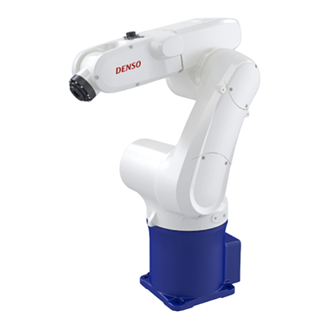
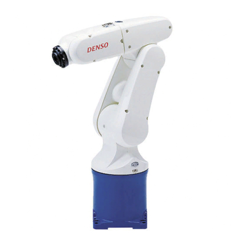
Denso HS-G Series Operating and safety instructions

ROBOT
Horizontal articulated
HS-G SERIES
INSTALLATION & MAINTENANCE GUIDE

Copyright © DENSO WAVE INCORPORATED, 2005-2011
All rights reserved. No part of this publication may be reproduced in any form or by any means
without permission in writing from the publisher.
Specifications are subject to change without prior notice.
All products and company names mentioned are trademarks or registered trademarks of their
respective holders.

Preface
Thank you for purchasing this high-speed, high-accuracy assembly robot.
Before operating your robot, read this manual carefully to safely get the maximum benefit from your robot
in your assembling operations.
Robot series and/or models covered by this manual
Model (Note 1)
Series
Floor-mount Overhead-mount
Overall arm length
HS-G
(Small-sized, horizontal articulated)
HS-4535*G
HS-4545*G
HS-4555*G
—
HSS-4545*G
HSS-4555*G
350 mm
450 mm
550 mm
NOTE 1: Model names listed above apply to the models of robot systems. The model names of robot
units are followed by M. If the robot system model is HS-4****E, for example, the robot unit model is
HS-4****E/GM (the robot unit of E to G series).
Important
To ensure operator safety, be sure to read the precautions and instructions in "SAFETY PRECAUTIONS."

How this book is organized
This book is just one part of the robot documentation set. This book consists of SAFETY PRECAUTIONS,
chapters one through three.
Chapter 1 Installing Robot Components
Provides information about physical site planning, installation procedures, and engineering-design notes
for hands.
Chapter 2 Customizing Your Robot
Describes how to customize your robot--defining the software motion space and restricted space,
CALSETing, and setting control set of motion optimization.
Chapter 3 Maintenance and Inspection
Describes the regular maintenance and inspections necessary for maintaining the performance and
functions of your robot.

Contents
Chapter 1 Installing Robot Components ........................................................................................................................ 1
1.1 Preparing a Proper Environment for Installation................................................................................................... 1
1.1.1 Ambient Temperature and Humidity .............................................................................................................. 1
1.1.2 Vibration......................................................................................................................................................... 1
1.1.3 Connecting the Robot Unit and Robot Controller .......................................................................................... 1
1.1.4 Installation Environment of the Robot Unit ................................................................................................... 2
1.2 Mounting the Robot Unit ...................................................................................................................................... 4
1.2.1 Transporting the Floor-Mount Type ............................................................................................................... 4
1.2.2 Transporting the Overhead-Mount Type (HSS-G series) ............................................................................... 6
1.2.3 Securing the Robot Unit ............................................................................................................................... 10
1.2.4 Grounding the Robot Unit ............................................................................................................................ 11
1.3 Installing the Robot Controller............................................................................................................................ 11
1.4 Electrical Wiring and Air Piping of the Robot Unit ............................................................................................ 12
1.4.1 Notes for Wiring and Piping Through a Hollow in the Z-axis Shaft ............................................................ 12
1.4.2 Reference Drawings for Stays that Clamp Wiring and Piping...................................................................... 13
1.4.3 Prohibition Against Use of Mechanical End Bolts and Mechanical Stoppers for Wiring or Piping............. 14
1.4.4 Piping of Source Air ..................................................................................................................................... 15
1.5 Installing the Flange Kit (Option) ....................................................................................................................... 16
1.6 Engineering-design Notes for Robot Hands........................................................................................................ 16
1.7 Moving Each Axis with Motor Power OFF in Emergency Stop .........................................................................17
1.8 Locking Out the Power Switch ........................................................................................................................... 19
Chapter 2 Customizing Your Robot .............................................................................................................................. 20
2.1 What Is Customization? ...................................................................................................................................... 20
2.2 Modifying Software Motion Limits to Define New Motion Space.....................................................................21
2.2.1 What Is a Software Motion Limit? ............................................................................................................... 21
2.2.2 Software Motion Limits (Factory defaults) .................................................................................................. 22
2.2.3 Changing Software Motion Limits ............................................................................................................... 24
2.2.4 Precautions When Changing the Software Motion Limits ........................................................................... 25
2.2.5 Procedure for Changing the Software Motion Limits .................................................................................. 25
2.3 Changing Mechanical Ends to Define New Restricted Space............................................................................. 28
2.3.1 What is a Mechanical End Change? ............................................................................................................. 28
2.4 Performing CALSET .......................................................................................................................................... 29
2.4.1 What Is CALSET?........................................................................................................................................ 29
2.4.2 Preparation for CALSET.............................................................................................................................. 30
2.4.3 Performing CALSET.................................................................................................................................... 32
2.5 Setting Control Set of Motion Optimization ....................................................................................................... 38
2.6 Setting Robot Installation Conditions ................................................................................................................. 38

Chapter 3 Maintenance and Inspection........................................................................................................................ 39
3.1 Maintenance & Inspection Intervals and Purposes ............................................................................................. 39
3.1.1 Precautions for installation and maintenance of robots for clean room use ................................................. 39
3.2 Daily Inspections................................................................................................................................................. 41
3.2.1 Check Items.................................................................................................................................................. 41
3.3 Quarterly Inspections .......................................................................................................................................... 43
3.3.1 Check Items and Lubrication........................................................................................................................ 43
3.3.2 Cleaning the Cooling Fan Filters in the Robot Controller............................................................................ 43
3.4 Semiyearly Inspections ....................................................................................................................................... 44
3.4.1 Lubrication ................................................................................................................................................... 44
3.5 Biennial Inspections ............................................................................................................................................ 45
3.5.1 Battery Replacement and Belt Inspection..................................................................................................... 45
3.5.2 Replacing the Encoder Backup Battery........................................................................................................ 46
3.5.3 Replacing the Memory Backup Battery ....................................................................................................... 50
3.5.4 Setting the Next Battery Replacement Date ................................................................................................. 50
3.6 Supplies for Maintenance.................................................................................................................................... 51
3.7 Replacing Fuses and Output ICs ......................................................................................................................... 51
3.8 Checking the Odometer and Trip Meter.............................................................................................................. 52
3.8.1 Displaying the Odometer and Trip Meter..................................................................................................... 52
3.8.2 Resetting the Trip Meter to Zero .................................................................................................................. 54
3.9 Checking the Controller ON-Time and the Robot Running Time and Resetting Their User Counters............... 55
3.9.1 Displaying the Controller ON-time and the Robot Running Time ............................................................... 55
3.9.2 Resetting the User Counters of the Controller ON-Time and the Robot Running Time .............................. 57
3.10 Backing up Projects............................................................................................................................................. 59
3.10.1 Back up project data ..................................................................................................................................... 59
3.10.2 Transfer arm data.......................................................................................................................................... 61

1
Chapter 1 Installing Robot Components
1.1 Preparing a Proper Environment for Installation
Before installing the robot unit and robot controller, confirm that the operating
environment is in conformity with each item of SAFETY PRECAUTIONS, "Installation
Precautions". Also, take proper measures to protect the components from vibration.
In an inappropriate environment, the robot will not operate to its full capacity or
performance, components may not last long, and unexpected failure may result.
.
1.1.1 Ambient Temperature and Humidity
Keep the ambient temperature between 0C and 40C during operation.
Keep the ambient humidity at 90% or below to prevent dew condensation.
1.1.2 Vibration
Do not install the robot in an environment where it will be exposed to excessive
vibration or impact.
1.1.3 Connecting the Robot Unit and Robot Controller
Before delivery, the robot unit and the robot controller are adjusted to each other as a
set. When two or more robots are to be used, use the robots and robot controllers that
have been adjusted to each other as a set.
Caution: The robot unit and robot controller in a set are given the same serial
number.

2
1.1.4 Installation Environment of the Robot Unit
The table below lists the installation requirements for the robot unit. Prepare a highly
rigid mount as shown on the next page.
Caution:
Do not electric-weld the equipment including the robot. A large
current may flow through the motor encoder or robot controller
resulting in a failure. If electric welding is required, remove the
robot unit and the robot controller from the equipment beforehand.
Installation Requirements for the Robot Unit
Item Environments and Conditions
Flatness of the mount 0.1/500 mm (See the next page.)
Rigidity of the mount Use steel materials. (See the next page.)
Installation type Floor-mount or overhead-mount (Only for HSS-G)
Ambient temperature During operation: 0 to 40ºC
During storage and transportation: -10 to 60ºC
Humidity
During operation: 90% or less (No dew condensation allowed.)
During storage and transportation: 75% or less (No dew condensation
allowed.)
Vibration During operation: 4.9 m/s2(0.5G) or less
During storage and transportation: 29.4 m/s2(3G) or less
Altitude During operation: 1,000 m or less
Safe installation
environment
Refer to the SAFETY PRECAUTIONS, 3.1 "Insuring the proper
installation environment"
Working space, etc.
• Sufficient service space must be available for inspection and disassembly.
• Keep wiring space (at least 190 mm for Standard type, at least 230 mm for
Dust-proof, splash-proof type) behind the robot, and fasten the wiring to the
mounting face or beam so that the weight of the cables will not be directly
applied to the connectors.
Grounding conditions Functional ground
See the figure given on page 11.

3
20 or more
1000 or less
100
100
pipe
500 or more
Caution (1) When the robot operates at high speed, the robot mount
undergoes large reaction forces. The mount must be rigid
enough so that it will not vibrate or be displaced due to
reaction forces. It is also advisable to mechanically join the
robot mount with heavy equipment.
(2) Some mounts may produce a resonance sound (howling). If
this sound is loud, increase the rigidity of the mount or
slightly modify the robot speed.
Robot Mount Sample for Floor-mount Type
Strut
Mounting face
350 350 20
or more
100
100
t6.0
(square steel pipe)
Caution (1) When the robot operates at high speed, the top plate
structure undergoes large reaction forces. The robot mount
must be vibration-proof so that the top plate will not vibrate
due to reaction forces. Also it must be designed to be
separated from other top plate structures in the equipment.
(2) Some mounts may produce a resonance sound (howling). If
this sound is loud, increase the rigidity of the mount or
slightly modify the robot speed.
Robot Mount Sample for Overhead-mount Type

4
1.2 Mounting the Robot Unit
Caution (1) Before handling or installing the robot unit, be sure to read
SAFETY PRECAUTIONS, "Installation Precautions."
(2) The grease is applied to the shaft and rack of the Z-axis for
lubrication and rust-proof. Do no touch or wipe the shaft and
rack so as to keep rust-proof.
1.2.1 Transporting the Floor-Mount Type
This section gives the typical installation procedure assuming that you have set up the
robot mount bed and prepared robot mounting bolt holes in it. If you have not done it
yet, first read Section 1.2.3 "Securing the Robot Unit."
Caution (1) The installation jobs should be handled by at least two
persons.
Robot unit weight: Approx. 25 kg (55 lbs)
(2) Be sure to put on a helmet, safety shoes, and gloves.
Step 1 Disconnect the motor cable, encoder cable, air pipes, hand, and tools from the robot
unit, if mounted.
(Illustration: HS-G)
Disconnect the motor cable, encoder cable, and others.

5
Step 2 Turn the 2nd axis until it comes into contact with the mechanical end in order to keep
the safe position. Then remove the four bolts and release the robot unit from the
pallet.
Caution: When worker A is removing those bolts, worker B should
support the 1st-axis arm to prevent the robot unit from
overturning.
(HS-G)
Step 3
Hold the robot unit as shown below. This job should be handled by two workers.
Caution (1) Do not hold the robot at sections other than those
specified below. The plastic cover could easily break.
(2) Before starting transportation, make sure that there are
no obstacles in the path to the mounting bed.
(HS-G)
Step 4 Put the robot unit on the mount bed and secure it with four bolts temporarily.
Step 5 Fix the robot unit, referring to Section 1.2.3 "Securing the Robot Unit."
Tightening torque: 70 14 Nm (For HS-G series)
Worker
A
Wor
k
er B
Turn until it
comes into
contact with the
mechanical
end.
Bolts
Bolts
Pallet

6
1.2.2 Transporting the Overhead-Mount Type (HSS-G series)
This section gives the typical installation procedure of the robot unit.
Caution (1) Since the robot unit weighs approx. 25 kg (55 lbs), prepare a
crane and forklift with a hoisting load of 0.2 ton or more.
(2) The overhead mounting job must be handled by at least two
persons including a qualified operator for sling, crane and
forklift operation.
(3) Be sure to put on a helmet, safety shoes, and gloves.
Step 1 When unpacked, the overhead-mount robot unit is fastened with rope as shown
below. Make sure that the robot's 2nd-axis arm cannot rotate.
Caution: NEVER remove the 2nd-axis arm fixing rope until the
installation of the robot unit is completed.
This is to prevent the robot arm from rotating unexpectedly
due to gravity.
<HSS-G>
2nd-axis arm
fixing rope

7
Step 2
A
s illustrated below, wind the belt sling around the robot base two turns and make a
knot on the side opposite to the power connector.
<HSS-G>
Step 3 Load the eyes of the belt sling on the hook of the crane.
<Example of HSS-G series>
Step 4 Remove the four bolts and release the robot unit from the pallet.
Caution: When worker A is removing those bolts, worker B should
support the robot unit as shown below to prevent it from
overturning.
<HSS-G>
Wire (Belt sling)

8
Step 5 While keeping the robot posture, slowly hoist the robot unit with the crane.
Caution: Before starting this job, make the work floor clear of
obstacles.
<HSS-G>
Step 6 If the crane hoists the robot unit until it may be turned upside down, stop the crane
and have two workers turn the robot unit upside down, as shown below.
<HSS-G>

9
Step 7 While having two workers keep the robot unit in the upside-down position, slowl
y
hoist the robot unit with the crane so that the robot base comes into contact with the
robot installation face of the overhead-mount frame. Secure the robot unit with fou
r
mounting bolts temporarily.
<HSS-G>
Step 8 Firmly secure the robot unit, referring to Section 1.2.3 "Securing the Robot Unit."
<For HSS-G Series>
Tightening torque: 70 14 Nm
<HSS-G>
Step 9
A
fter completing bolting, unhook the belt sling from the crane and then remove the
2nd-axis arm fixing rope.
Caution: Store the 2nd-axis arm fixing rope for future removal of the
robot unit.

10
1.2.3 Securing the Robot Unit
(1) According to the dimensions specified in the figure below, drill four robot fixing holes
and two dowel pin holes in the robot mount where the robot unit is to be anchored.
Drilling in the robot mount
Drilling in the robot mount For HS/HSS-G series
Four robot fixing holes M10 bolt holes, a minimum of 20 mm deep
For diamond-shaped pin 4H7 dia. hole a minimum of 10 mm deepTwo holes for
dowel pins For internally-threaded
positioning pin
6H7 dia. hole, a minimum of 10 mm deep
(2) Drive a diamond-shaped pin into the hole (HS/HSS-G: 4H7 dia.) so that the pin
becomes oriented as shown below.
(3) Drive an internally-threaded positioning pin into the hole (HS/HSS-G: 6H7 dia.).
Caution: Never skip this step. These dowel pins can minimize the risk of
misalignment that could be caused by replacement of the robot unit
during maintenance or due to vibration.
(4) Put the robot unit on the robot mount, following the transport instructions given in
Section 1.2.1 "Transporting the Floor-Mount Type" or Section 1.2.2 "Transporting the
Overhead-Mount Type."
(5) Secure the robot unit with four bolts and plain washers.
Fixing bolts: M10 x 30 mm, JIS strength class: 12.9 (For HS/HSS-G series)
Tightening torque: 70 14 Nm (For HS/HSS-G series)
(For HS/HSS-G series)
Bolt Positions for Securing the Robot Unit
Front
Diamond-shaped pin
Reference hole

11
1.2.4 Grounding the Robot Unit
Ground the grounding terminal of the robot unit using a wire of 5.5 mm2or more.
Caution: Use a dedicated grounding wire and grounding electrode. Do
not share them with other power facilities or welding machines.
(HS/HSS-G)
Grounding the Robot Unit
1.3 Installing the Robot Controller
For the installing procedures of the robot controller, refer to the RC7M CONTROLLER
MANUAL, Section 6.2 "Installing the Robot Controller."

12
1.4 Electrical Wiring and Air Piping of the Robot Unit
Make electrical wiring and air piping for the hand or tool to be attached to the arm end,
referring to the either of examples (1) and (2) below.
(1) Using a hollow provided in the Z-axis shaft
Robot model HS/HSS-G series
Hollow diameter in the Z-axis shaft 14
(2) Securing a stay to the robot unit for clamping wiring and piping
Wiring and Piping Image (HS-G series)
1.4.1 Notes for Wiring and Piping Through a Hollow in the Z-axis Shaft
The Z-axis shaft has a hollow through which you may make wiring and piping from the
hand control signal connector (CN21) or air piping joints on the top of the 2nd arm.
In this wiring and piping, check that:
(1) When the robot is in motion, the wiring and piping do not become taut or interfere
with other sections.
(2) During up- or down-movement of the Z-axis, the wiring and piping inside the hollow
do not become taut or interfere with other sections.
(3) Making the wiring and piping able to be pulled out through the hollow makes
maintenance easy.
Wiring and piping through a hollow
(14 dia.) in the Z-axis shaft
Stay
Secured with
two M3 bolts
Securing a stay that clamps wiring
and piping

13
1.4.2 Reference Drawings for Stays that Clamp Wiring and Piping
When mounting a stay that clamps wiring and piping to the robot unit, be sure to secure
it with at least two screws using the four existing internal threads provided in the
underside of the second arm.
Referring to the drawing given below, set up a stay.
Note:Maintenance and inspection of the robot unit sometimes requires removing
and installing the covers. Mount the stays for wiring and piping so that they
will not interfere with removal/installation of the covers.
HS/HSS-G series
Internal threads (M3, 6 mm deep)
Reference drawing for a
stay
Second arm First arm
Internal threads (M3, 6 mm deep)
2nd-axis
arm
1st-axis
arm
Stay
Material: SPCC (t2.0)
Surface treatment: Galvanizing
Viewed from
A
Existing internal thread positions

14
1.4.3 Prohibition Against Use of Mechanical End Bolts and Mechanical
Stoppers for Wiring or Piping
Never remove the 1st- or 2nd-axis mechanical end bolts or 3rd-axis mechanical
stoppers shown below or use them for securing a stay that clamps wiring or piping.
Doing so may result in the following problems: The CALSET initial position will be
deviated when CALSET is performed; software limits will become invalid; the robot arm
will fail to run as programmed; the robot arm will interfere with its peripheral devices;
and so on.
For HS-G series
1st-axis mechanical
end bolt
2nd-axis mechanical
end bolt
3rd-axis mechanical
stoppers
Other manuals for HS-G Series
1
Table of contents
Other Denso Robotics manuals

Denso
Denso VS-G Series Operating and safety instructions

Denso
Denso VP-G SERIES Configuration guide

Denso
Denso RC5 User manual

Denso
Denso VP-G SERIES Operating and safety instructions

Denso
Denso Faber HM-G Series Configuration guide

Denso
Denso VM-G Series Operating and safety instructions

Denso
Denso HS-G Series Configuration guide

Denso
Denso VS-6556G User manual