De Agostini MODEL SPACE Robi User manual

Build your own
16
Pack
Stages 59-62:
Begin working
on the inside of
Robi’s head

All rights reserved © 2016
Published in the UK by De Agostini UK Ltd,
Battersea Studios 2, 82 Silverthorne Road,
London SW8 3HE
Published in the USA by De Agostini Publishing
USA, Inc., 121 E. Calhoun Street
Woodstock, IL 60098
Packaged by Continuo Creative,
39-41 North Road, London N7 9DP
Printed in EU
The names and likenesses of all Robi characters,
artwork and distinctive lettering are protected
under the copyright and trademark laws of the
United States and all foreign countries.
CONTENTS
Build your own
Assembly Guide p320
Stage 59: Test Robi’s neck, back and arms p320
Stage 60: Prepare and fit Robi’s head servos p328
Stage 61: Build up Robi’s head p338
Stage 62: Fit Robi’s first infrared eye sensor p342
™
www.model-space.com
NOT SUITABLE FOR CHILDREN UNDER THE AGE OF 14.
THIS PRODUCT IS NOT A TOY AND IS NOT DESIGNED FOR USE IN
PLAY. ITEMS MAY VARY FROM THOSE SHOWN. THERE MAY BE
COLOUR VARIATIONS OWING TO THE MATERIALS USED.

STAGE 59:
TEST ROBI’S NECK,
BACK AND ARMS
Use the CPU board to test Robi’s neck, body and arms,
before fittin the velvet pads supplied in this stae to his feet.
This stae beins with you testin all the
servos of Robi’s neck, back and arms
toether, to ensure they all work before
you seal them inside Robi’s body. You will
then start buildin up the frame that will
hold both of Robi’s head servos, by
securin this to the neck base and servo
assembly via the servo itself. Finally, you
will attach the velvet pads supplied in
this stae to the soles of Robi’s feet.
Unlike the double-sided adhesive pads
used in Pack 9, these pads come in a left
and riht shape, so make sure you use
the correct one!
ASSEMBLY GUIDE
1
2
3
4
56 7 8
9
You will be usin parts from previous staes,
so be sure to have these to hand before beinnin.
1 Head servo frame
2 Head lever
3 Lever ring nut
4 Velvet foot pads
5 M1.7 x 24mm pan-head screws x 3
6 M3 x 8mm pan-head screws x 2
7 M2 x 6mm pan-head screws x 2
8 M2 x 6.2mm pan-head screws x 2
(one of each screw is a spare)
9 Servo cable 70mm
YOUR PARTS
PARTS TO BE
ASSEMBLED
Power distribution board
(Stage 40)
Neck stand
(Stage 53)
Body
(Stage 58) Legs and hip base
(Stage 52)
Protective pads
(Stage 3)
Battery
(Stage 38)
SAVED PARTS
320

FASTEN THE NECK PLATE
TEST THE SERVOS
Use an M2 x 6.2mm pan-head screw to secure the part,
but do not tighten it too much, as the plate needs to be
able to move. You received a number of screws with this
stage, so make sure you use the correct one – this one
was part number 8 in the list.
Hold the body as shown, then push the switch
to the ON position.
Connect the battery’s connector to the socket
marked CN1 on the power distribution board. Make
sure the battery is charged (see box, above).
Now take the free connector on the body’s power/switch cable
and fit this into CN3.
12
3
45
Position the circled end of the neck plate fitted in the
previous stae over the hole in the scarf beneath.
To rechare Robi’s
battery, connect
the battery and
power cord to the
power distribution
board, in sockets
CN1 and CN3
respectively, then
plu the mains
charer into the
back of the rear
hip panel.
RECHARGING
THE BATTERY
POWER DISTRIBUTION
BOARD SOCKETS CN1
AND CN3 CHARGER
CABLE
321
Still holding the battery in place,
turn the switch ON. Note: Robi’s
arms will move as soon as the
power is switched on!
Slide the battery into the space next to the back servo, making sure all the
connectors stay in their sockets. Hold the battery in place.
When the power is connected, Robi will perform a movement test of his arms, by setting them to their starting, or neutral,
position, stretching them outwards from the elbows, then bringing them back to the neutral position.
Next, Robi’s upper arms will lift outwards – and while this
happens, his neck servo will pan to the right and back.
Finally, Robi’s shoulders will extend his arms forward
over his chest – and the shaft of his back servo will
rotate to the left.
76
8
910
STARTING
POSITION ELBOWS
STRAIGHTENED STARTING
POSITION
UPPER ARMS
RAISED
NECK ROTATES
BACK SERVO ROTATES
SHOULDERS LIFT
ARMS FORWARD
322

When the tests described on the previous pages are
complete, Robi will return to his neutral position and you
will hear him say ‘OK!’ This is to test his speaker. Turn the
switch back to OFF, and disconnect the switch cable and
battery from the power distribution board.
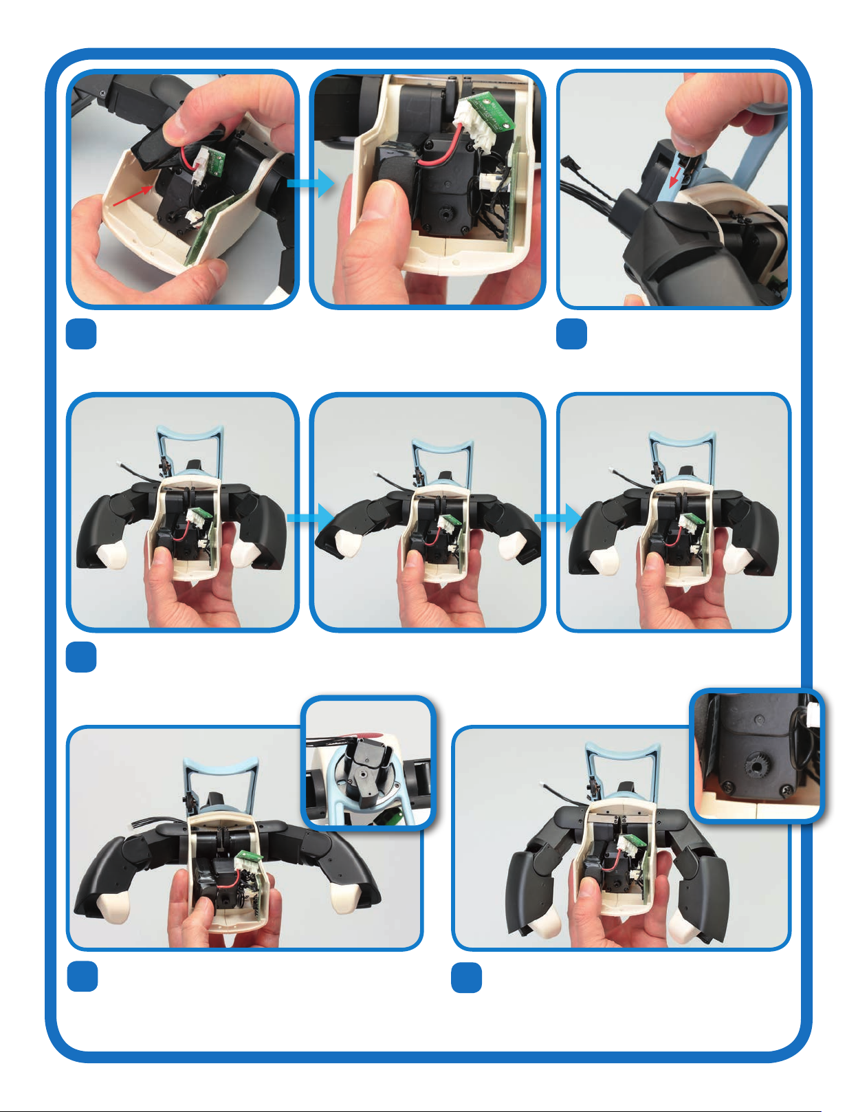
Line up the head servo frame to the neck
servo, as shown.
Set the frame on top of the neck servo, so that the circled holes align
with the free ones on the neck servo. Then insert and tighten two
M1.7 x 24mm pan-head screws into these holes.
Now locate the circled hole in the top of the frame. Insert an M2 x 6mm pan-head screw into this hole to
secure the part.
11
OK!
STARTING
POSITION Each of the white plastic
connectors has a small barb
on one side, which holds the
connector securely in its
socket. To unplug a connector
easily and safely, press the
barb inwards – never pull on a
connector without doing this!
ATTENTION! !
Both arms were tested in
Stages 43 and 44, so if they
do not work now it is most
likely a problem with the
connection to the CPU, so
check/reset this.
Remove the back servo’s
cable from the CPU and
check to see if the arms start
working.
Consult the troubleshooting
guide of this stage.
IF THE ARMS DO NOT
MOVE
IF NO SERVOS MOVE
IF THE BACK AND NECK
DO NOT MOVE
Robi saying ‘OK!’ is only to test his speaker, not to affirm that the movement
test went as planned. If the movement tests do not go as described, see the
box above right, or the troubleshooting guide later in this stage.
12 13
14 15
ATTACH THE HEAD SERVO FRAME
323

FIT THE HEAD LEVER
Take the head lever and fit the ring nut into the hole in its longer arm,
from the angle shown. The ring nut should fit perfectly.
Take an M3 x 8mm pan-head screw and insert it through the circled
hole in the inside of the head servo frame, entering from the left. Turn
the screw through this hole so that it travels through the ring nut in the
lever and out to the other side.
With the ring nut still in position, slide the
lever into the space in the middle of the
head servo frame. Its shorter arm should
be at the rear of the assembly, pointing
out towards Robi’s right arm.
Holding the ring nut in its hole, line up the
lever to the head servo frame, oriented as
shown above.
16
19
18
17
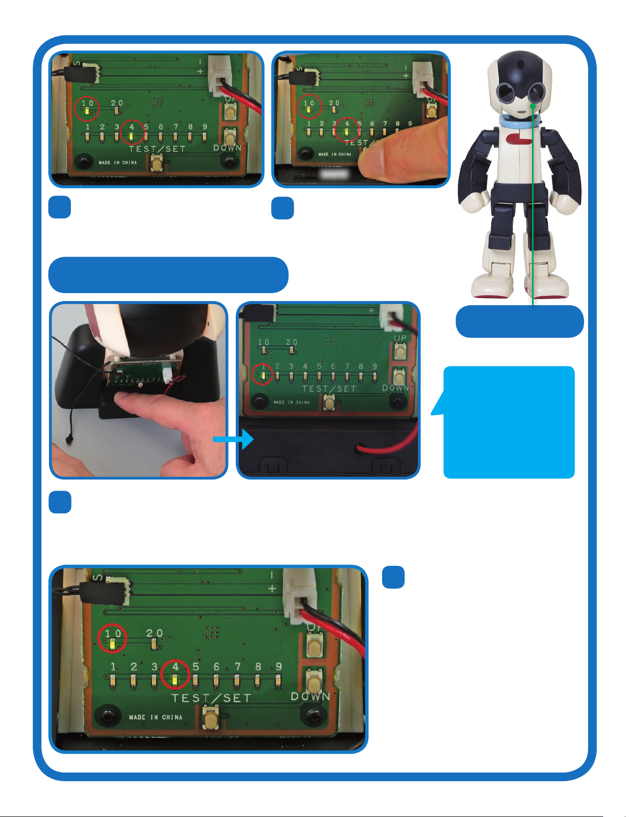
TEST AND FIT SERVO ID=15
20 21
Make sure the test board is switched OFF, then
connect its own servo cable to it.
Turn the board ON. The LEDs should flash, and then leave the
1 LED lit alone.
324

22
23 24
Press the TEST/SET switch: Robi’s head should rotate 45° to the left, stop, then
move back across to 45° to the riht, before returnin to its oriinal position. The
next step is to set the servo’s ID number, so keep the power on. If the test does not
run, or if the LEDs flash rapidly, refer to the HELP box in Stae 8.
Althouh this servo has been used for Robi’s
neck durin the testin process, it will be his
forward-tiltin head servo when fitted, with
the ID number 15. To set this, press UP 14
times, so that the 10 and 5 LEDs liht up.
Press and hold down the TEST/SET button
for a few seconds. The 10 and 5 LEDs
should flash, then remain lit. The ID number
is now set.
If the test does not
run, check the servo
cable’s connector,
and ensure that the
battery is charged.
ID=15
25 It is vital that Robi’s servos are set correctly,
so it is always a ood idea to check that you
have set the intended ID number afterwards.
To do this, leave the servo connected, then
switch the power OFF, then back ON. Only
the 1 LED should liht up.
26 To check the ID number, press TEST/SET briefly. Now the 10 and 5
LEDs should liht up and the servo shaft should repeat the rotations
seen in the test. Note: if anythin is amiss, you can bein the settin
process aain from Step 23.
CHECKING THE ID NUMBER
It is normal for the 1 LED to
light up when you switch on.
It will only change to give you
the ID number of the servo
when you press TEST/SET. If
you made a mistake, or set the
wrong ID number, you can reset
it by going through the setting
procedure again.
As you will have seen in the previous few packs, the process of
checking and resetting a servo’s ID number once fitted can be
fiddly and time-consuming, so be sure to get it correct now!
!
325

FITTING THE FOOT PADS
PREPARING THE SERVO CABLE
27 28
Match the riht foot pad to the sole of Robi’s riht foot, then,
when you are sure that they alin, peel the backin away to
the middle. Press the heel of the pad onto the back of the
sole, then smooth it down from the back to the front, peelin
the rest of the backin away as you do.
Make sure that the pad fits exactly: if it doesn’t, peel it away
and reset it. Once you are happy with it, repeat the process
for the left foot and pad.
29 30
As you have done previously, identify the side of this
stae’s servo cable connector that has PUSH marked
on it (circled).
Apply a pad to the connector on this side. Repeat for the
other end of the cable.
If you want to delay fitting
the pads until the cable is
used in the build, you may
do so.
Remember, to see all of Robi’s assembly
stages, including this one, visit the
ModelSpace web page at:
www.model-space.com
Assembled
body and feet
326
TROUBLESHOOTING
In this section, we look aain at what to do if the movement test carried out in this stae does
not o as described. As the arms have been tested previously, we will focus on the operation
of the neck and back servos, as well as the speaker, from which Robi says ‘OK!’
Before dismantlin the assembly to check its individual servos, check the other electrical components used in the test.
HEAD/NECK/BACK SOCKET
CHECK THAT THE CABLE IS CONNECTED TO
THE CORRECT SOCKET ON THE CPU
CHECK THAT THE SERVO CABLE IS
SECURELY CONNECTED TO THE CPU
CHECK THAT THE
BATTERY IS CHARGED
Ensure that the back servo
cable’s connector is sittin
securely within its socket.
Remove and replace it carefully
if need be.
The socket farthest from
the micro SD card slot on
the CPU board will hold the
servo cable runnin from
the back servo.
The test will only run if sucient
power is received from the
battery, so make sure the battery
is fully chared (see the Close-
Up box earlier in this stae).
INITIAL CHECKS
Neck stand (Stage 53)
Alon with the Phillips screwdriver
supplied with Stae 2, you will need
the followin:
IF NEITHER THE NECK NOR BACK SERVOS MOVE,
OR IF ROBI DOES NOT SAY ‘OK!’
If neither the neck nor the back servo moves when you start
the test, it is probable that there is a misplaced connection,
so o back and check these. Similarly, if Robi does not say
‘OK!’ at the end of the test, you should check the connection
between the speaker cable and CPU board.
THE BACK SERVO
THE SPEAKER
Follow the assembly of Steps
14-19 of Stae 58 in reverse, and
check the back servo’s connections
carefully. If both were sound,
disconnect it from the neck servo
and check the servo’s ID number
(ID=12), resettin it if necessary.
If Robi does not say ‘OK!’ at the
end of the test, check the connection of the speaker cable to
the CPU – done in Step 15 of Stae 57.
IF ONLY ONE SERVO MOVES
If one servo moves but the other does not, it is likely that one
of the ID numbers has been set incorrectly.
Should you need to disassemble and reset Robi’s neck or back
servos, see Stae 58 (for the back servo, ID=12) and/or Stae
54 (for the neck servo, ID=13).
327

You will be usin parts from the
previous staes, so be sure to have
these to hand before beinnin.
STAGE 60: PREPARE
AND FIT ROBI’S
HEAD SERVOS
Prepare Robi’s second head servo then fit it, alon with the
one from the previous stae, to his head servo frame.
There are two servos inside the upper
part of Robi’s head, ID=14 and ID=15.
Both are set onto the head servo
frame that you fitted and wired over
the previous staes, and they will work
in tandem with the internal lever and
head base to make Robi’s head tilt
forward and back (in the case of
ID=15) and side to side (ID=14). As
ever, take care when handlin open
servos, and make sure you set the
correct ID number.
ASSEMBLY GUIDE
1
PARTS TO BE
ASSEMBLED
1 Servo motor (ID=14)
YOUR PARTS
SAVED PARTS
Neck stand
(Stage 53)
Battery
(Stage 38)
Power distribution board
(Stage 40) Body and neck assembly, and
servo cable (Stage 59)
328
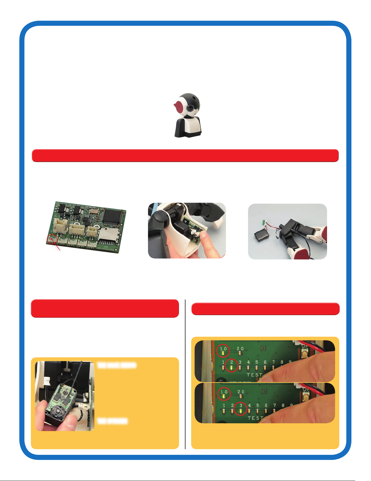
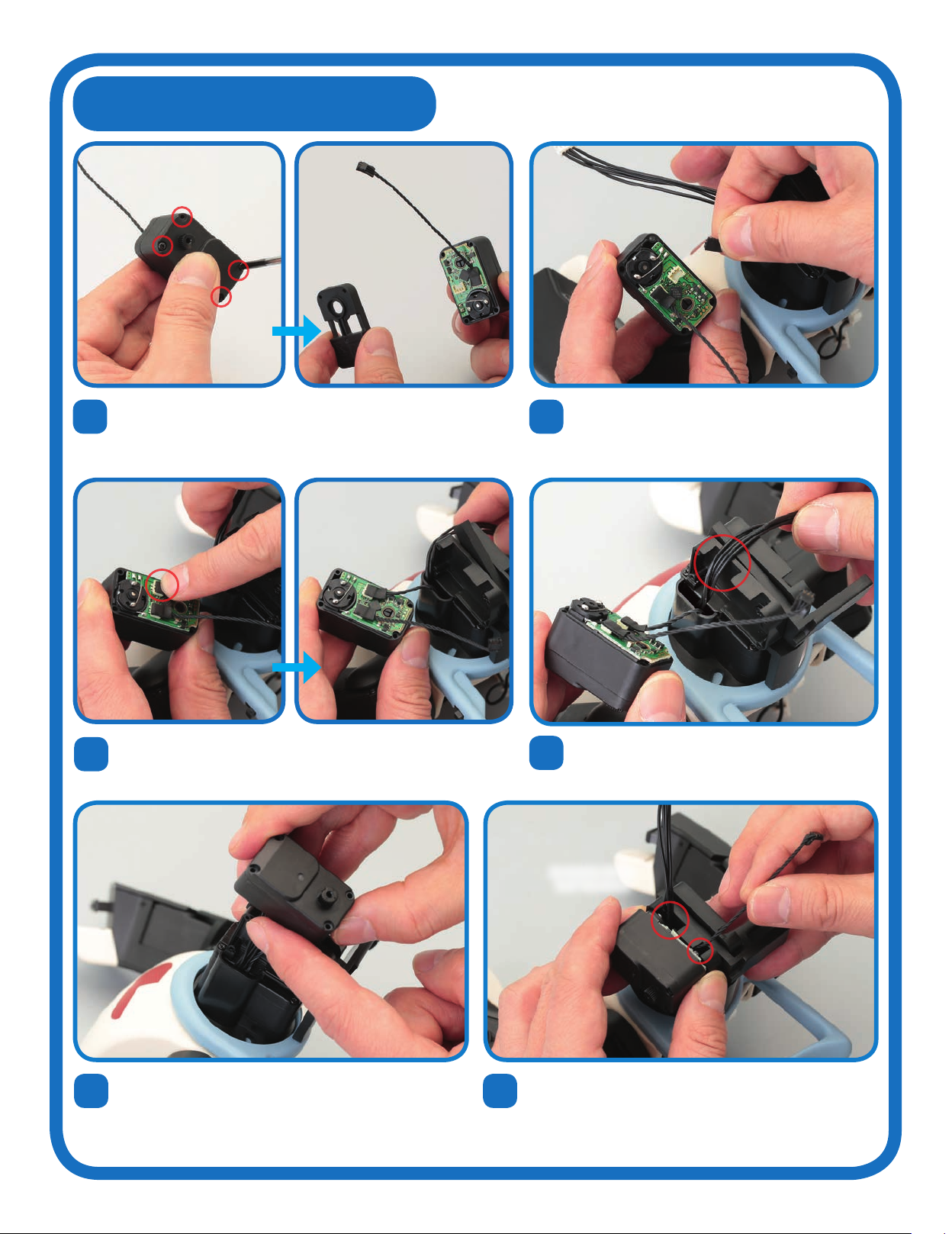
THE SERVO AND CABLE
2
3Hold the open servo with the circuit board facing upwards. Fetch the
servo cable fitted with protective pads in the previous stage, and press
one of its connectors into the socket circled in red, as you have done
before. It does not matter which end of the servo cable you use.
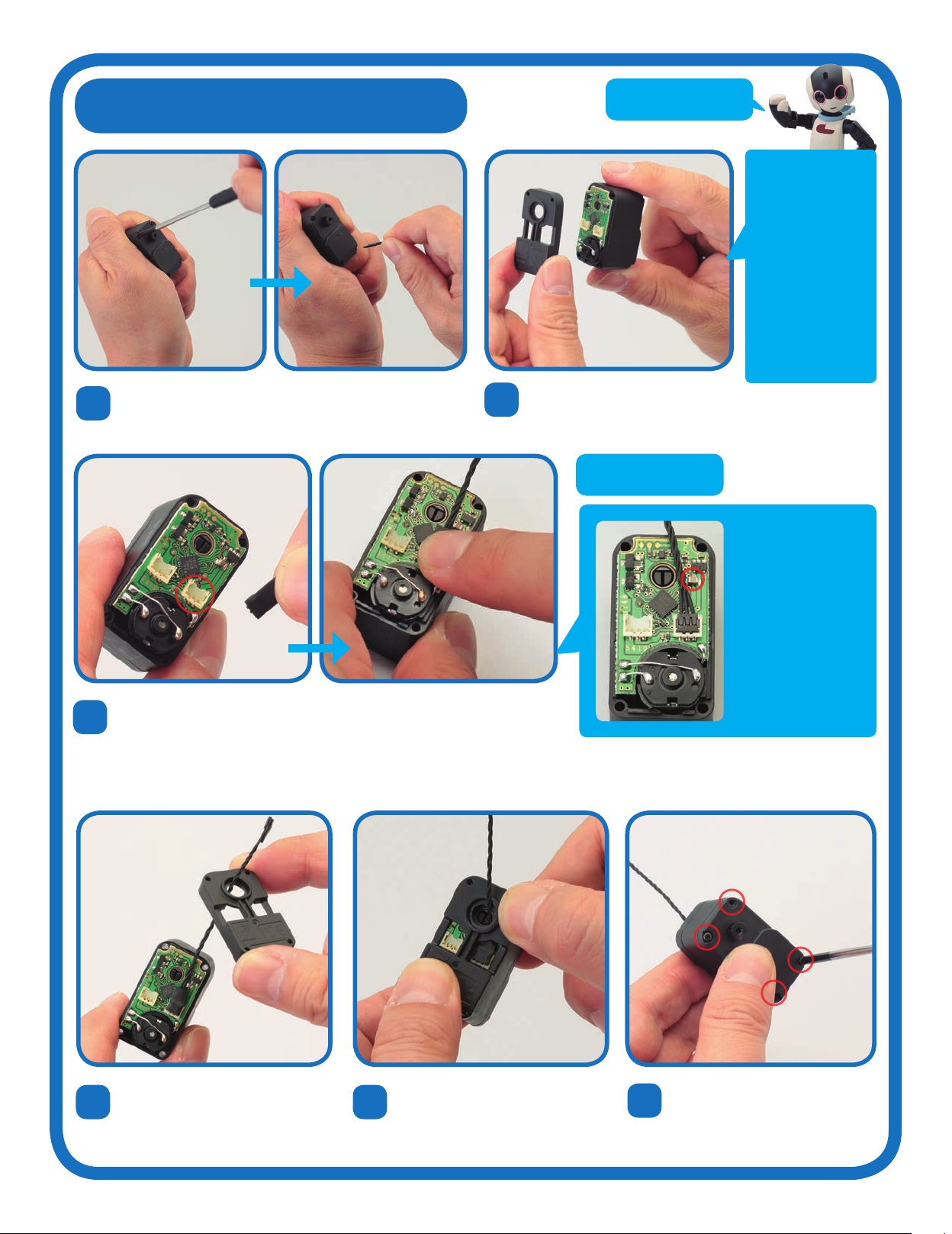
Gently lift the cover away, takin
care not to force it or damae
the circuit board underneath.
1Take out the four screws holdin the servo’s removable
cover in place, and keep these safely to one side.
As ever, it is very
important that the
electronic parts
exposed by removin
the servo’s cover are
not touched in any
way. Make sure to hold
the open servo by its
sides, and if you put it
down on your work
surface durin the
assembly, do this with
the open side facin
upwards.
4Pass the free end of the servo
cable throuh the circular hole in
the removable cover, as shown.
56
Press the cover back into place
on the servo’s main housin.
Fasten the cover back into place
with all four screws, but only
lihtly, as you will be removin
them aain at a later stae.
TIP!
TIP!
This servo cable had
protective pads fitted
to its connectors in the
previous stage, but if you
find it difficult to attach
with a pad in place, it is
possible to fit the pad
afterwards. If you choose
to do the assembly this
way, be especially careful
not to press down on the
circled projection, next to
the cable, as you do so.
329
TESTING THE SERVO
8
7Take the neck stand and make sure the power pack is
turned OFF. Carefully unplu the black servo cable from
the socket on the left of the test board, and attach the
servo cable connected to the servo in Step 3.
With the servo connected, switch the power to ON. After
the LEDs blink twice, only the 1 LED should liht up.
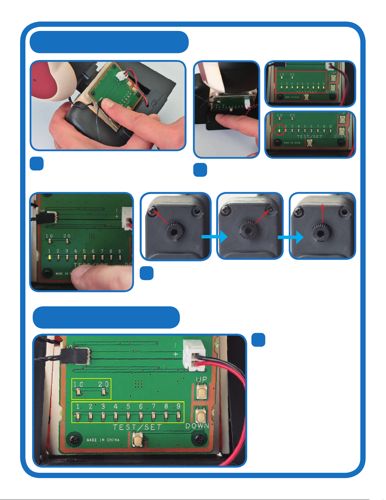
9To test the servo, press the TEST/SET switch: the servo’s shaft should rotate 45°
to the left, stop, then move back across to 45° to the riht. The next step is to set
the servo’s ID number, so keep the power on. If the test does not run, or if the LEDs
flash rapidly, refer to the HELP box in Stae 8.
SETTING THE ID NUMBER
10 Next, you will set the ID number
of the servo usin the test board,
as you have done before. Each
time you press the UP switch, the
ID number increases by one, and
the result is displayed by the two
banks of LED lihts. The top row
reads in tens and the bottom in
units. For example, to set the ID to
14 as you will do in this stae, you
press UP 13 times. This will liht
up the 10 and 4 LEDs. (If you
overshoot, press the DOWN switch
to take it down one step at a time.)
When the ID number is correct,
you set it by pressin and holdin
the TEST/SET switch.
9
Units
Tens
330
TEST/SET
ID=14
11 12
To set the head servo to ID=14, press UP 13
times, so that the 10 and 4 LEDs are lit.
Pressin DOWN will adjust this if you
overshoot while doin this.
Once the numbers are correct,
press and hold TEST/SET for a few
seconds. The LEDs will blink, then
stay lit, confirmin that the ID is set.
13 It is vital that Robi’s servos are set correctly, so it is always a ood idea to check
that you have set the intended ID number afterwards. To do this, leave the servo
connected, then switch the power OFF and back ON aain. After blinkin, only the
1 LED should liht up.
14 To check the ID number, press TEST/SET
briefly. Now the 10 and 4 LEDs should
liht up and the servo shaft should repeat
the rotations seen in the test. Note: if you
find that a servo has the wron number
assined to it, o back and repeat the
settin process in full.
CHECKING THE ID NUMBER
It is normal for the 1 LED to
light up when you switch on.
It will only change to give you
the ID number of the servo
when you press TEST/SET. If
you made a mistake, or set the
wrong ID number, you can reset
it by going through the setting
procedure again.
331
BE CAREFUL NOT TO
TRAP THE CABLES
ATTACH THE FIRST HEAD SERVO
15
17
19 20
16
18
Remove all four screws aain from the servo prepared in this stae
(ID=14) and remove its cover. You will not be usin the cover aain.
Set the neck servo’s cable connector into the free socket on the
head servo ID=14.
With the VR cable still in the larer cutaway, brin the open
face of the servo towards the head frame, with the servo
shaft at the rear of the assembly, closest to Robi’s scarf.
Make sure the VR cable is still in the larer cutaway,
then run the servo cable into the smaller cutaway in the
frame. Be careful not to disturb the connectors on the
servo’s face as you do this, or to trap or pinch any of the
cables themselves.
Line up the servo to the left-hand side of Robi’s
neck base. Take the servo cable leadin from the
neck base in your hand.
Run the four-strand VR cable, also leadin from the
neck base, into the larer, circled cutaway in the left
side of the head servo frame.
332

21
22
24
26
23
25
Join the servo to the frame – checkin aain as
you do so that none of the cables are trapped, and
that the connectors stay in place. Use all four screws removed in Step 15 to secure the servo to the
head frame.
Remove all four screws holdin the neck servo in place. Keep
these, as you will be usin them aain.
Now unhook the servo cable by hand to free servo ID=15.
Carefully remove Robi’s head from the neck stand.
Gently lift the servo away from its base, but do not
move it far enouh to disconnect the servo cable.
REMOVING SERVO ID=15
333

27
29
31
30
28
Position servo ID=15 next to the free side of the head
frame, on the riht side of Robi’s neck base. Line up the
servo cable leadin to servo ID=14, fitted in this stae, to its
open face.
Brin the servo to the frame, and pass the servo cable
connected in the previous step throuh the circled cutaway.
Use all four screws removed in Step 24 to secure the servo to the head frame.
Join the servo to the frame, makin sure the servo cable
is not trapped and remains neatly in the cutaway. Pullin
ently upwards as you combine the parts will achieve this.
Connect this servo cable to one of the sockets. The other
will not be used.
MAKE SURE THE CABLE
IS NOT TRAPPED
ATTACH THE SECOND HEAD SERVO
334

ROBI’S HEAD, NECK STAND AND TEST BOARD
Robi’s head contains a number of his most vital electronic components, which you will
bein to add in the comin staes. The first components you will fit, in Stae 62, are the
infrared sensors that identify movement and are set into the centre of his eyes. Then, later
on, you will add the LEDs that illuminate his eyes and liht up his mouth to ive him his
expressive character. The head will also hold key parts used for his voice-reconition
capabilities, and more!
Robi’s head
Althouh you have disassembled the neck stand in recent
staes, you will be usin it and the test board that it holds
aain, so keep it safely until then!
USING THE NECK STAND AND TEST BOARD
Althouh you have removed the scarf, neck servo and head, you will continue usin the neck stand, and the test board it
holds, to check or reset servos’ ID numbers. The process for doin this will be the same as before, thouh is actually a
little more straihtforward, as you can now use the neck stand’s existin servo cable (previously used to connect the
neck servo) to connect to the servo in question. The steps for performin a servo test this way are found below.
1Ensure the neck stand’s servo
cable is connected securely to
the test board, then set the
other end to the servo you wish
to check/reset.
2Bein the process of testin/
resettin the chosen servo in
the usual way.
3To complete the test, simply turn
the test board OFF and carefully
disconnect the servo.
335

TEST THE NECK AND HEAD SERVOS
32
35 36
37
33 34
Push the switch on the scarf
to the OFF position.
Turn Robi’s switch ON.
The test will bein as
soon as power is turned
on, so be prepared!
As well as the servos
focused on in these steps,
the arms will also move,
so hold Robi in a way that
will not interfere with this.
The test will bein once the power is turned on.
First, observe the left-hand head servo, ID=14,
which will return to its neutral position, then
rotate a small way clockwise, raisin the D-cut
section upwards. Look very closely, as the
movement will be minimal (inset). Robi’s neck
servo, ID=13, will then rotate. Once that is done,
Robi will say ‘OK!’
While the neck servo is performin its
rotation, Robi’s second head servo,
ID=15, will also run its test, this time
rotatin anticlockwise a little to
aain raise its D-cut upwards
(inset). Once you are happy
with the test, disconnect
the power.
Connect the battery to the power
distribution board, in socket CN1.
Now connect the power/switch cable to
socket CN3.
STARTING
POSITION
STARTING
POSITION
Remember, to see all of Robi’s assembly
stages, including this one, visit the
ModelSpace web page at:
www.model-space.com
Assembled
body and
head servos
Each of the white plastic
connectors has a small barb
on one side, which holds the
connector securely in its
socket. To unplu a connector
easily and safely, press the
barb inwards – never pull on a
connector without doin this!
ATTENTION! !
Robi sayin ‘OK!’ is only to test his speaker, not to arm that the
movement test went as planned. If the movement tests do not o
as described, see the box in Stae 59, or the troubleshootin uide
later in this stae.
336

TROUBLESHOOTING
In this section, we look aain at what to do if the movement test carried out in this stae does
not o as described. As the arms have been tested previously, we will focus on the operation
of the neck and back servos, as well as the speaker, from which Robi says ‘OK!’
Before dismantlin the assembly to check its individual servos, check the other electrical components used in the test.
HEAD/NECK/BACK SOCKET
CHECK THAT THE CABLE IS CONNECTED TO
THE CORRECT SOCKET ON THE CPU
CHECK THAT THE SERVO CABLE IS
SECURELY CONNECTED TO THE CPU
CHECK THAT THE
BATTERY IS CHARGED
Ensure that the back servo
cable’s connector is sittin
securely within its socket.
Remove and replace it carefully
if need be.
The socket farthest from
the micro SD card slot on
the CPU board will hold the
servo cable runnin from
the back servo.
The test will only run if sucient
power is received from the
battery, so make sure the battery
is fully chared (see the Close-
Up box in Stae 59).
INITIAL CHECKS
Neck stand (Stage 53)
Alon with the Phillips screwdriver
supplied with Stae 2, you will need
the followin:
IF NEITHER HEAD SERVOS MOVES
If neither head servo moves when you start the test, it is
probable that there is a misplaced connection, so o back
and check these. If this does not resolve the issue, you will
need to check/reset their ID numbers.
DISASSEMBLY
Follow the assembly of Steps 15-31 of this stae in reverse, and
carefully check the connections made in the steps before. If
both were sound, you will need to check the servos’ ID numbers,
resettin them if necessary.
IF ONLY ONE SERVO MOVES
If one servo moves but the other does not, it is likely that one
of the ID numbers has been set incorrectly.
If you need to reset Robi’s head servos, they are ID=14 (left-
hand side of head servo frame, prorammed in this stae) and
ID=15 (riht-hand side of frame, prorammed in Stae 59).
337
Other De Agostini Robotics manuals


