dentalfarm W.A.FI.S. Manual

DUST FILTERING SYSTEM
W.A.FI.S. Electric Version
MAINTENANCE AND INSTRUCTION MANUAL

DESCRIPTION
W.A.FI.S. is a dust suction, filtering and elimination system (DENTALFARM exclusive
patent) expressly studied to work in conjunction with the Dentalfarm sandblaster models
which can be easily connected to any blasting chamber.
The system fully complies with international existing rules referred to environmental
hygiene.
The WAFIS system definitevely solves the problems related to the toxic dust originated
during any sandblasting process by the impact of the abrasive grains on both investment
and casting oxidations. The level of dust elimination attained, certified by an official
institute, covers 99.8% of the total dust developed.
The size and the power are compared to the requirements of the Dental Laboratories.
Maintenance and consumption are very restricted thanks to the high reliability of this
entirely pneumatic machine.
POSSIBILITIES OF CONNECTION FOR THE WAFIS
Connection of the WAFIS to a blasting machine is very simple
but two different procedures have to be followed according to:
A) if the WAFIS has to be connected to Dentalfarm already
pre-arranged blasters:
1) release the connection flange to the working chamber;
2) push and turn clockwise to connect the hose (24) of
WAFI.S. on the same flange;
3) place your WAFIS on the floor and connect the other
end of the pipe to the upper manifold (30), adjusting its
length in order to avoid any siphons or very tight
curves;
B) if the WAFIS has to be connected to other machines not
pre-arranged, and even not manufactured by DENTALFARM,
you should:
1) remove the dry filtering bag wherever it is located;
2) stop up definitively the free hole;
3) find a suitable location to connect the dust suction
system; we recommend to install it on the back panel of the working chamber, not
too low in order to avoid abrasive from being sucked, too but also distant from the
area under the blasting jet in order to avoid the pipe from being struck.
4) utilize the flange supplied as drilling jig to carry out the four
fixing holes (∅4,5 mm) and fix in place with the screws;
5) drill additional holes in the middle, having the correct diameter
sufficient to ensure the dust particles to blow quickly away;
6) turn clockwise to fit the WAFIS flexible hose onto the flange;
7) place your WAFIS on the floor and connect the other end of
the pipe to the upper manifold, adjusting its length in order not
to make siphons or very tight curves.
INSTALLATION INSTRUCTIONS
/!\
ATTENTION:
The WAFIS must be positioned on the floor, under or near the
bench where the sandblaster has been placed. The connection
pipe must fall perpendicularly avoiding any pockets and/or
siphons which may collect sediment inevitably causing am loss in
the intake power (eventually cut the pipe).
To arrange the machine, follow these instructions:
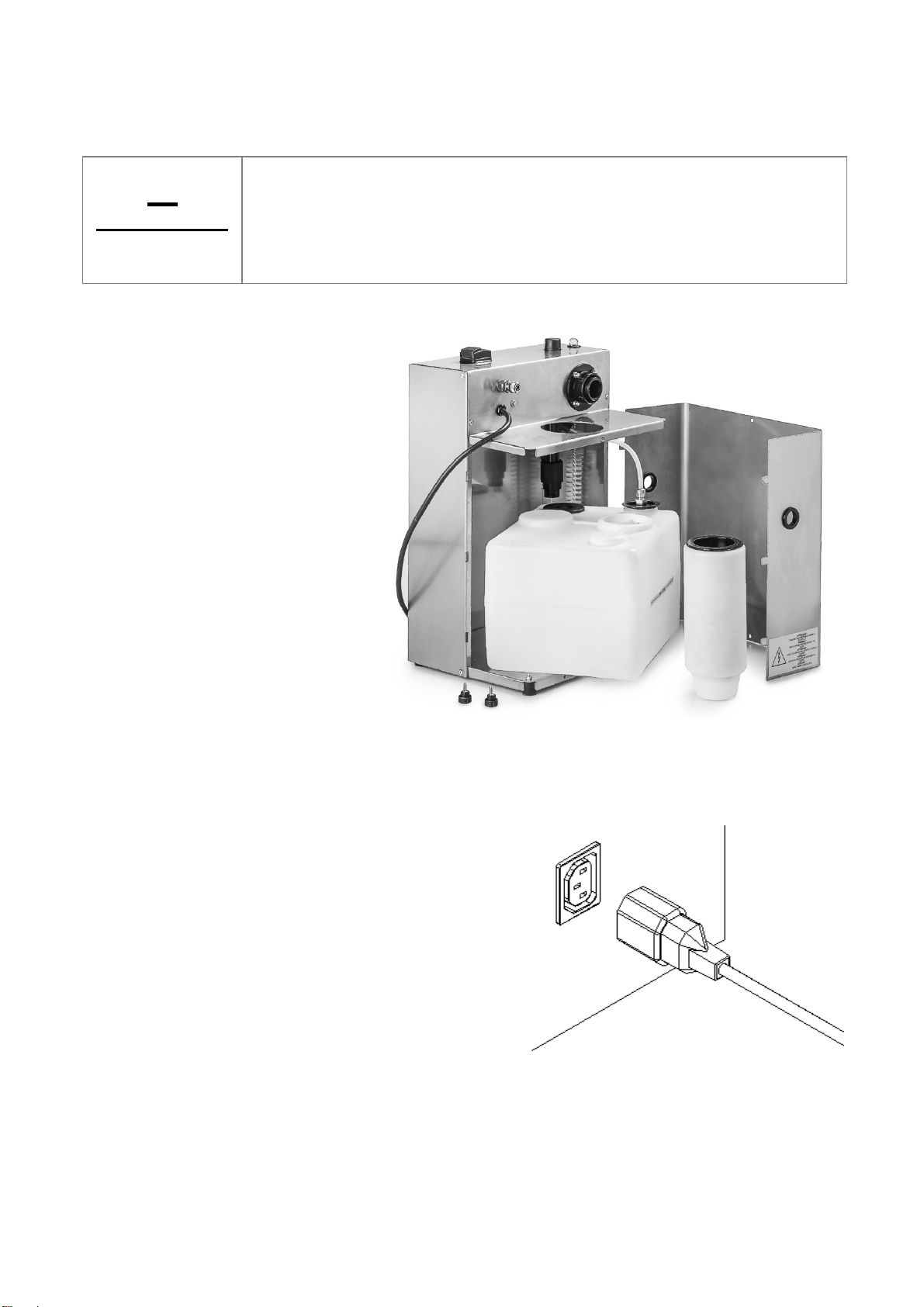
A)fill the internal tank
• loosen the pressure knobs
to remove the panel (23)
• remove the air outlet pipe
from the water tank (12)
• pull to disassemble the
water injector (10) from the
depressor body (29)
• lift the connection sleeve
(29) making it slide on the
smooth side of the
depressor (29)
• pull out the tank (14) and
fill in with water up to the
maximum limit (WATER
LEVEL)
• re-assemble every
component paying attention to the watertight seals.
B)connect pneumatically the machine to proper pipe-fitting (9) (rilsan or polyethylene 8x6
pipe) a special pipe-fitting for the rubber pipe is also supplied, eventually replace.
C) Connect the feeding cable (7) to the proper
plug located at the base of the machine (if any)
or use the supplied cable (8) to tie into a
standard 230V AC outlet with ground.

INSTRUCTIONS FOR USE
To operate the WAFIS system connected to a pre-arranged DENTALFARM sandblaster, it
is sufficient to leave the switch (pos. 1) on and turn the light on.
On the other hand, in case the WAFIS is connected to the power outlet, you must turn on
acting on its own switch.
The operating principle is very simple: the electric impulse opens the solenoid valve: the
air flow will pass from the spraying nozzle, enter the depressor body where, by expanding,
it creates vacuum and causes the dust particles to be sucked. The filtering system is
originated in the upper portion of the pipe where the air mixed up with dust particles is
sprinkled by a fine jet of atomized water; the dust particles become heavier and are then
separated from air which can not be moistened and will accumulate on the bottom of the
collection tank.
MAINTENANCE INSTRUCTIONS
The only maintenance operations required are:
• the regular cleaning of the depressor (30): remove the cap (3) and introduce the
cleaning swab (1) provided for that specific purpose - Frequency: once a day.
• the water replacement in the internal tank: operate as for the first installation but
taking care to clean carefully all the components - Frequency: once every 15/20
days.
GUIDE TO SOLVE THE PROBLEMS
Problem: DUST IS COMING OUT FROM THE BLASTING CHAMBER
Possible cause Remedy
The depressor is clogged
Activate the depression system, remove the cap or the
suction pipe, introduce the cleaning swab and let it
slide repeteadly to eliminate any residuals. It could
also be necessary to clean the connection area
between the working chamber and the pipe itself.
The depressor nozzles are dirty
or clogged Pull out the water feeding injector and clean it with a
proper tool. Repeat the same operation with the air
injector and introduce it in its seat checking that the
side opening corresponds to the water inlet.
The water filter is clogged Replace it.
The exhaust pipe is clogged
Disconnect from the tank, clean the metallic straw
(wash and blow), ev. replace.
PNEUMATIC CIRCUIT
No.
1
2
3
4
5
DESCRIPTION
SOLENOID VALVE
DEPRESSOR
SEDIMENT COLLECTION TANK
EXHAUST PIPE
SUCTION PIPE
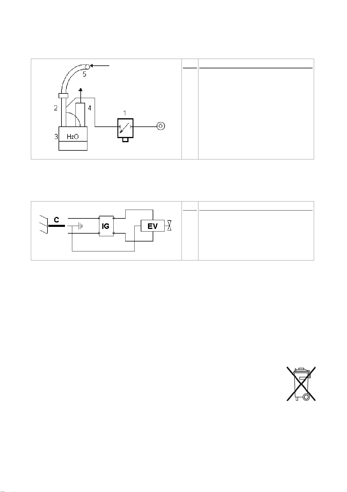
WIRING DIAGRAM
No.
IG
EV
C
DESCRIPTION
MAIN SWITCH (4)
SOLENOID VALVE (6)
FEEDING CABLE (7-8)
TECHNICAL REFERENCE REGULATIONS AND TEST PROCEDURES
Every unit is mass-manufactured by DENTALFARM in compliance with technical and
safety rules in force, as provided for by the 2006/42 EEC Community Directive on
Machinery. Careful inspection and full routine testing are carried out singularly on each
filtration system.
DEMOLITION AND WASTE DISPOSAL
According to International regulations, this unit has been classified as AEE
(electric and electronic device, whose correct operation depends on electric
currents and electromagnetic fields) and as a consequence, at the end of its
lifetime, it can not be treated as normal waste material but it must be disposed
separately, complying with the Directive 2002/96/CE.

EXPLODED DRAWING AND SPARE-PART LIST
No CODE DESCRIPTION
1 RCS044 DEPRESSOR CLEANING SWAB
2 NEA111 PLASTIC FERRULE D.=16
3 RCB030 DEPRESSOR INSPECTION CAP
4 NEC016 MAIN SWITCH
5 1201021 STAINLESS STEEL HOUSING
6 NES029 WAFIS SOLENOID VALVE + CONNECTOR
7 NEV014 ELECTRIC CABLE 3X1 WITH IEC320 PLUG
8 NEV013 FEEDING CABLE
9 NPR119 8x6 1/8” MALE STRAIGHT PIPE-FITTING
-- NPR220 7 1/8” PIPE-FITTING
10 RCB034 DEPRESSOR WATER INJECTOR
11 NVP040 6x4 PIPE FOR PNEUMATIC CONNECTIONS
12 RCB514N EXHAUST PIPE COMPLETE
13 NEA113 JOINT FOR WATER TANK
14 1201023 FILTERING TANK COMPLETE
15 NVI010 WATER FILTER
16 NVP060 8x6 PIPE FOR PNEUMATIC CONNECTIONS
17 NPR104 8x6 1/8” FEMALE STRAIGHT PIPE-FITTING
18 RCB080 FILTER FITTING CAP
19 NPR111 6x4 1/8” MALE STRAIGHT PIPE-FITTING
20 NVG049 RUBBER FEET
21 NEA101 FAIR-LEAD
22 1201022 MOBILE PANEL
23 NVT151 M 4 KNOB
24 NEV060 30x36 FLEXIBLE CONNECTION HOSE
25 RWA007 SUCTION PIPE FIXING FLANGE
26 RWA006 FLANGE JOINT
27 RCB070 DEPRESSOR MANIFOLD
28 NPOR128 OR128 JOINT ON MANIFOLD
29 1039029 DEPRESSOR PIPING
30 1039028 DEPRESSOR MANIFOLD
-- RCB501 DEPRESSOR COMPLETE
31 RCB033 DEPRESSOR AIR INJECTOR


TECHNICAL DATA
Height 410 mm
Width 275 mm
Depth 220 mm
Net Weight 5.7 Kg
Gross Weight 7.2 Kg
Minimum working pressure 2 BAR
Maximum working pressure 6 BAR
Air consumption 28 l/min at 2 BAR - 63 l/min at 5 BAR
Number of machines which can be connected 2
Maximum distance allowed between devices 1.5 meters
Percentage of eliminated dust 99,8%
Power tension 230v - 50Hz
DENTALFARM s.r.l.
Via Susa, 9/a - 10138 TORINO - ITALY
COMMERCIAL SERVICE - (+39) 011/4346588
AFTER SALE SERVICE – (+39) 011/4346632
FAX – (+39) 011/ 4346366
E-MAIL - [email protected]
WEBSITE: www.dentalfarm.it
Table of contents
Popular Water Filtration System manuals by other brands

3P Technik
3P Technik VF1 Installation and maintenance instruction

Concoa
Concoa 580 6001 Assembly, installation and operation instructions

Sven
Sven Platinum Pro Operation manual

Pentair
Pentair Cristal-Flo Installation and user guide

BWT
BWT MINISTIL 1iD Installation and operating manual

3M
3M Aqua-Pure AP801 Housing Installation and operating instruction manual


