Denton Vacuum DESK V User manual
Copyright Denton Vacuum, LLC. All Rights Reserved. Version 9142016da 1
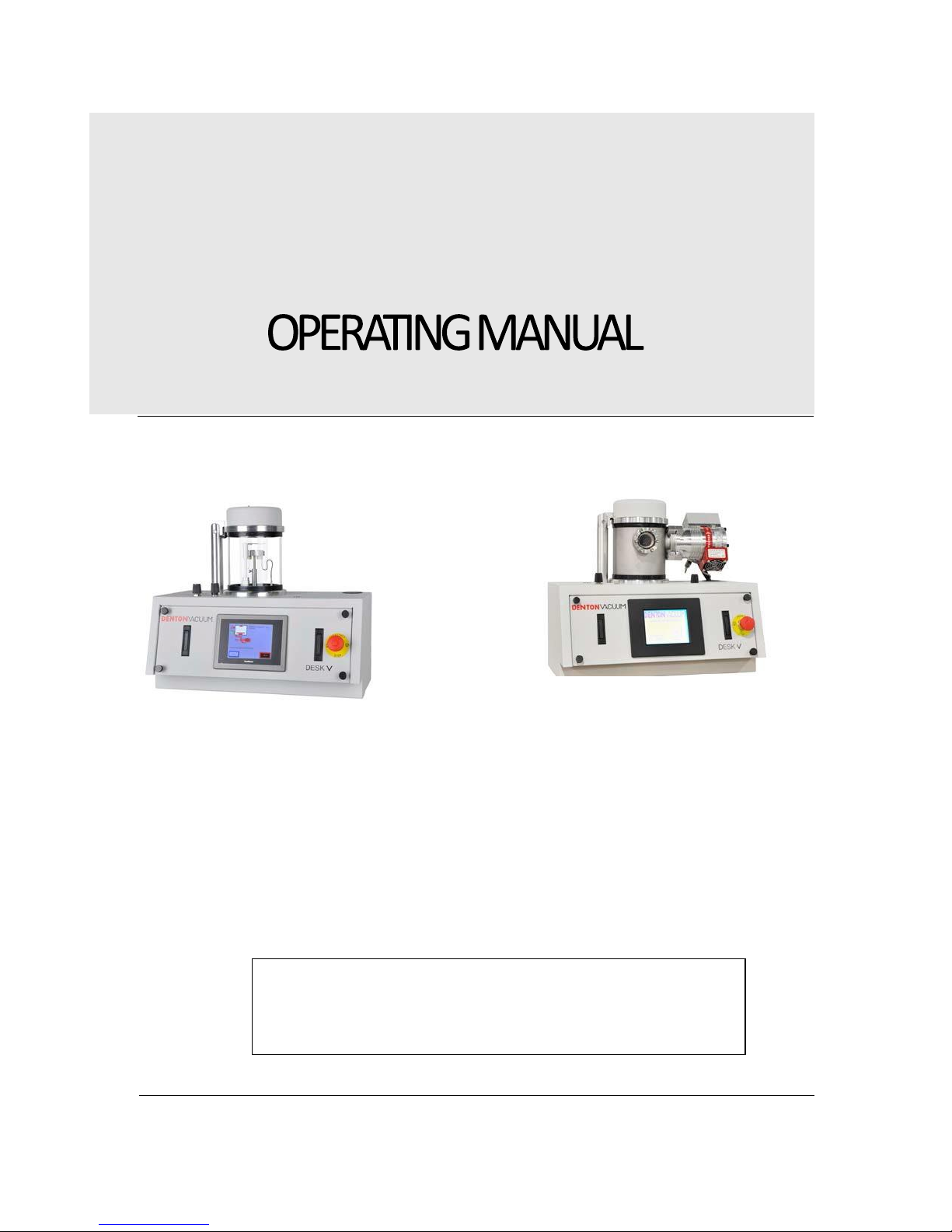
Desk V
DESKV-SPUTTER/ETCHUNITANDACCESSORIES
DENTON VACUUM, LLC
1259 N. CHURCH STREET
MOORESTOWN, NJ 08057
PHONE:856-439-9100
FAX:856-439-9111
WWW.DENTONVACUUM.COM
DENTONVACUUM
DESKV
Desk V
Desk V TSC
Watch the Desk V videos here:
https://www.youtube.com/user/Dentonvacuum

Copyright Denton Vacuum, LLC. All Rights Reserved. Version 9142016da 2
Table of Contents
Contents
INTRODUCTION ...............................................................................................................................................................5
GENERALDESCRIPTION............................................................................................................................................5
SYSTEMVIEWS.......................................................................................................................................................6
FRONTVIEW OF UNIT...............................................................................................................................................6
REAR VIEW OF UNIT.................................................................................................................................................7
ELECTRICALREQUIREMENTS.....................................................................................................................................8
DESK V HP & DESK V TSC ..........................................................................................................................................8
CARBON ROD ACCESSORY AND CARBONYARN ACCESSORY .......................................................................................9
ENVIRONMENTALCONDITIONS ................................................................................................................................9
OPTIONS ........................................................................................................................................................... 10
ROTATION .............................................................................................................................................................10
THICKNESS MONITOR.............................................................................................................................................10
CARBON ROD EVAPORATION..................................................................................................................................10
CARBON YARN EVAPORATION ................................................................................................................................10
SAFETYWARNINGS ......................................................................................................................................................... 10
SAFETYSYMBOLS.................................................................................................................................................. 13
UNPACKING&SETUP ....................................................................................................................................................... 13
SYSTEM .............................................................................................................................................................. 13
Emergency Stop Button........................................................................................................................................14
INSTALLATIONINSTRUCTIONS...............................................................................................................................................15
VOLTAGE SELECTION ......................................................................................................................................... 15
........... 15
CHAMBER PREPARATIONS......................................................................................................................................18
MECHANICAL PUMP INSTALLATION ......................................................................................................................... 19
The mechanical pump installed ............................................................................................................................... 19
TARGET INSTALLATION & REPLACEMENT .................................................................................................................... 21
INITIAL START-UP .................................................................................................................................................... 22
INSPECTION......................................................................................................................................................... 22
START-UPPROCEDURE .............................................................................................................................................. 23
OPENINGTHECHAMBER........................................................................................................................................ 24
DESCRIPTIONOFCONTROLS ............................................................................................................................................... 25
SYSTEMSTARTSCREEN...........................................................................................................................................25
SCREENS ...............................................................................................................................................................26
Verifythattheincomingpowerconnectionissetforthepropervoltage!

Copyright Denton Vacuum, LLC. All Rights Reserved. Version 9142016da 3
.................................................................................................26
MANUAL SPUTTER ............................................................................................................................................ 27
St an d ar d Desk V HP ...........................................................................................................................................27
.....................................................................................27
MANUAL SPUTTER DESK V TSC.......................................................................................................................... 29
TIMED SPUTTER.....................................................................................................................................................31
Desk V TSC .............................................................................................................................................................. 32
Desk V Timed Recipe Programming......................................................................................................................34
How to Use Timed Recipe Programming..............................................................................................................35
MANUAL ETCH .....................................................................................................................................................37
DESK V HP................................................................................................................................................................ 37
TIMED ETCH...........................................................................................................................................................40
OVERVIEW.............................................................................................................................................................42
OPERATION...................................................................................................................................................................44
ETCH ................................................................................................................................................................. 45
SPUTTER............................................................................................................................................................. 47
TIMEDETCHOPERATION ........................................................................................................................................ 49
TIMEDSPUTTEROPERATION................................................................................................................................... 50
SHUT-DOWNPROCEDURE...................................................................................................................................... 52
OPTIONS ............................................................................................................................................................ 52
QUARTZ CRYSTALMONITOR...................................................................................................................................52
DESK V TSC ............................................................................................................................................................53
CARBON ROD ACCESSORY ......................................................................................................................................54

Copyright Denton Vacuum, LLC. All Rights Reserved. Version 9142016da 4
CARBON YARN ACCESSORY .......................................................................................................................................57
Loa d i ng the Carb on Yarn ............................................................................................................................ 58
MAINTENANCE ............................................................................................................................................................. 59
GENERALMAINTENANCE....................................................................................................................................... 59
MECHANICALPUMP ..............................................................................................................................................59
MECHANICAL PUMP –OIL CHANGE ........................................................................................................................60
SPUTTERTARGET....................................................................................................................................................60
TROUBLESHOOTING ................................................................................................................................................62
VACUUMPERFORMANCEDATASHEET .................................................................................................................................... 64
USEDTARGET ................................................................................................................................................................ 65
TYPICALPERFORMANCEDATA ............................................................................................................................................. 66
PUMPDOWN ...................................................................................................................................................... 66
DEPOSITIONRATE................................................................................................................................................. 69
PACKINGDESKVFORRETURN.............................................................................................................................................72
PACKINGPHOTOS ................................................................................................................................................. 73
SUGGESTEDSPARES ......................................................................................................................................................... 74
CONSUMABLESFORDESKVANDTSC....................................................................................................................... 74
FUSES.................................................................................................................................................................75
CONSUMABLESFORCARBONRODACCESSORY.......................................................................................................... 76
CONSUMABLESFORCARBONYARNACCESSORY ........................................................................................................ 77
TARGETSFORDESKVANDTSC ................................................................................................................................ 78
AdjustingtheVacuumSafetyBellowsSwitch........................................................................................... 79
Emergency Stop Button........................................................................................................................................80
Battery Advisory: ..................................................................................................................................................80

Copyright Denton Vacuum, LLC. All Rights Reserved. Version 9142016da 5
INTRODUCTION
GENERALDESCRIPTION
The Denton Vacuum DESK V Cold Sputter/Etch Unit is designed to deposit a conductive coating on an
SEM sample and to provide some limited surface cleaning in some models.
A standard 6”diameter Glass Cylinder with top and bottom seals sits on the aluminum Baseplate.
Metal chamber is optional with Turbo Pump option (TSC).
A two-stage, direct-drive Mechanical Pump, is located outside of the system cabinet,
evacuates the cylinder. Turbo molecular pump is optional (TSC).
An automatic Vent Valve is slaved to the mechanical pump. It will automatically open when the
Mechanical Pump is turned OFF to vent the chamber to atmosphere. It will automatically close when
the Mechanical pump is turned on.
An insulated Specimen Table with provisions for height adjustment is mounted within the Pyrex
cylinder. Rotation is optional.
The Sputter Cathode is clamped to an insulated aluminum plate in the chamber cover.
A manual Shutter is provided to shield the Sputter Cathode from contamination during the Etch
cleaning cycle. The shutter control knob is left of the chamber. Clockwise rotation of the knob will
open the shutter and counterclockwise rotation will close it.
A manual Gas Control is provided to control pressure in the cylinder. The Gas Control knob is to the
left of the chamber.
For servicing and inspection convenience, all Fuses are mounted externally on the rear panel and the
rear panel is hinged to provide access to internal components.
There are six main operations for the system: Vacuum, Etch Enable (if equipped), Rotation (if
equipped), Sputter Enable, Timed Etch (if equipped) and Timed Sputter.
A Programmable Logic Controller (PLC) controls the system. A Touch Screen is used to interface with
the PLC. Operator interface is through a graphics program that is running on the Touch Screen. This
control system will be described in detail in the Operation section of this manual.
NOTE:Thesystemoffersyouarangeofthinfilmprocessoptions.
However,it is importantto notethatwithallof thissystem’s potential,thereexistsafety
considerations.Individualswhoare to operate,service,or maintainthissystemshould
familiarizethemselveswiththismanual.
This manual suits for next models
1
Table of contents
Popular Laboratory Equipment manuals by other brands


Belden
Belden HIRSCHMANN RPI-P1-4PoE installation manual

Koehler
Koehler K1223 Series Operation and instruction manual

Globe Scientific
Globe Scientific GCM-12 quick start guide

Getinge
Getinge 86 SERIES Technical manual

CORNING
CORNING Everon 6000 user manual

Biocomp
Biocomp GRADIENT MASTER 108 operating manual


