dentronix DDUS60 User manual
DDUS60 and DDUS60R
Ultrasonic Cleaning System
Owners Guide


Owners Guide 3
Dentronix®Ultrasonic Cleaner
CAUTION: Federal law restricts this device to sale by or on the
order of a dentist and/or physician.
An essential part of your infection control system
Congratulations on your purchase of a Dentronix Ultrasonic Cleaner.
Developed specifically for the orthodontic industry, Dentronix units
feature unique product design and optimize time and safety in the
office. Dentronix offers a complete line of ultrasonic cleaning sys-
tems and cleaning solutions which provide you with the flexibility to
efficiently clean instruments.
What is ultrasonic cleaning?
Ultrasonic Cleaning is a process created by high frequency sound
waves. The sound waves, enhanced by specially formulated clean-
ing solutions, create high energy cavitation. During cavitation,
millions of tiny bubbles form and then collapse or “implode,”
releasing enormous amounts of energy and shock waves which
scour the surface of instruments, appliances and other apparatus
placed in the cleaning solution. This powerful scouring action
reaches into minute crevices, which manual brushing cannot reach.
The combination of energy and specially formulated solutions make
ultrasonic cleaning the most effective method for removing gross
and microscopic debris.
I. Unpacking
A. Remove your Dentronix unit from the shipping container and
inspect the unit for any possible damage which may have
occurred during shipping.
B. Check the serial number of the unit (found on the back side of
the unit) with the number on the shipping carton. If they are not
the same contact Dentronix.
C. Fill out the warranty card and mail to Dentronix within 10 days
of receipt.
D. Select a location for the cleaner. It should be close to a sink or
to waste lines to facilitate draining. The hose supplied with the
unit will allow you to place the unit on either side of the sink or
connect directly to the waste line. When used in conjunction with
a Dentronix DDS5000 dry heat sterilizer, find the best position for
your ultrasonic unit by calling Dentronix and asking for informa-
tion regarding “Sterilization Perfect Design.”
E. Connect one end of the hose to the drain valve (Fig. 1) and
place the other end in the sink. If desired (and recommended for
the DDUS60R), have your plumber connect the hose directly to
the waste system with the appropriate fittings per your local
building code.
II. Installation Instructions for the
DDUS60R Recessed Unit
The Dentronix DDUS60R consists of:
• Tank enclosure
• Electronics enclosure
• Drain tube
• Coaxial cable which is connected between the N female
coaxial connectors on the electronics control housing and the
tank housing
• Four-conductor cable which connects between DIN connec-
tors on the tank enclosure and the electronics enclosure
• Power supply cord
• Four (4) #8 Philips head wood screws
NOTE: Before you begin, please read and understand the safety
instructions provided by the manufacturers of the tools required
for installation.
Tools Required
1 Electric Drill
1 Drill bit to drill a hole large enough to accept a reciprocating
saw blade
1 Reciprocating saw and blade
1 Phillips head screw driver
1 Flat blade screw driver
NOTE: This Ultrasonic Cleaner must be installed by an experi-
enced equipment manager or licensed contractor. Be sure to
follow local building codes.
A. Tank Enclosure
1. Select a location for the cleaner. There must be at least 13"
clear vertical space below the top of the counter to accom-
modate the tank enclosure, and an additional 6" at the loca-
tion of the valve, for a total of 19". The countertop must be flat
and level. Make sure that you are not selecting a location
which will interfere with the drawers or vertical partitions
between cabinets.
2. Tape the enclosed template down to the countertop in the
desired location. Make sure the printed Dentronix logo on the
bezel faces you.
3. Drill four (4) 3/8" diameter holes where indicated on the
template (marked “A”).
4. Drill four (4) holes holes at the four locations marked “B.”
Select your hole size based upon the saw you will use in #5
below.
5. Cut along the “cut line” with a jigsaw or other reciprocating
saw.
6. Clean away dirt or sawdust around the opening, and remove
scrap wood.
7. Place tank enclosure into opening with the printed Dentronix
logo on the bezel facing you.
8. Assemble the bearing plates, lock washers and wing nuts to
the tie-down studs (per Detail A on the template).
9. Tighten all the wing nuts a few turns at a time until the bezel
just contacts the countertop. Once the bezel has contacted
the countertop on four sides, back off each wing nut 1/4 turn.
10. Apply a thin bead of clear RTV silicone sealant between the
bezel and countertop.
B. Electronic Enclosure
1. Select a location for the electronics enclosure which will be
conveniently close to the tank enclosure.
NOTE: Mount control unit so that the fuse drawer is acces-
sible (Section X, sub C). Be sure to leave at least 4" between
the back and sides of the electronic control housing and
cabinet wall. This will allow for adequate ventilation as well as
facilitate the insertion and removal of power/RF cables.

4Dentronix Ultrasonic Cleaner
NOTE: The side of the unit has ventilation louvers. Position
electronics control housing in such a way that liquids cannot
flow into the unit.
2. Four (4) #8 Phillips head wood screws have been included if
you wish to mount the electronics enclosure to one of the inte-
rior cabinet walls. Four adhesive-backed rubber feet have
been applied to the underside of the electronic control unit.
3. Connect the two cables between the electronics control box and
the tank enclosure. The cables are configured such that they
cannot be inserted into the wrong receptacle. If you have diffi-
culty plugging in a cable, check that it matches the receptacle.
4. Plug the power cord into the electronics control box, then into
a power outlet.
WARNING: Power should not be supplied to the unit until all
interconnections between the electronics enclosure, tank
enclosure and any accessories are securely connected.
WARNING: This unit must be properly grounded. Failure to
properly ground unit may result in serious injury.
5. The hose supplied with the DDUS60R allows waste disposal
in accordance with your local, state and/or federal regulations.
III. Operating Instructions
A. General Cleaning
1. Fill the tank with water to the fill line indicator (Fig. 2).
2. Pour the required amount of Dentronix DMP-US+Ultrasonic
Cleaning Solution or other Dentronix ultrasonic cleaning solu-
tion into the tank.
NOTE: Never operate the unit without solution. Operating a dry
tank may result in permanent damage to the unit and void the
warranty. Do not place objects directly on bottom of tank. Use
accessory baskets, cassette racks or beaker positioning cover.
3. Plug the line cord into a grounded AC outlet (or per local
regulations).
4. To activate the unit, turn the timer knob to the desired cleaning
time. The pilot light will glow when the unit is in operation. The
unit will automatically shut off at the end of the cycle.
5. Change the solution in the tank daily, or sooner if it appears
soiled or discolored. When beakers are used, change the
solution in the beaker after each use.
6. Drain unit by opening the valve and allow solution to empty
into sink or waste system. Rinse tank and close valve.
B. Degassing
Degassing the ultrasonic solution is an important step. Degassing
is the removal of large air bubbles found in all fresh solution, which
act as a barrier to efficient cleaning. Degassing is necessary
every time new solution is added. Degas the solution by activating
the unit for 15 minutes before you add any items to be cleaned.
C. Cover
The Dentronix Ultrasonic Cleaner should always be covered when
operating to trap aerosols in the unit. The Dentronix DDUS60
and DDUS60R are equipped with a “hinged” cover for easy,
one-hand opening. The cover conveniently lifts off for cleaning
and may also be used as a carrying tray for accessories.
D. Instrument Draining
The DDUS60 and DDUS60R are equipped with a bezel
surrounding the tank. The bezel drains condensation back into
the tank, keeping the work area around the unit dry. The bezel
also acts as a draining stand for the large basket or cassette
racks. Simply position the corner of the basket or rack on two of
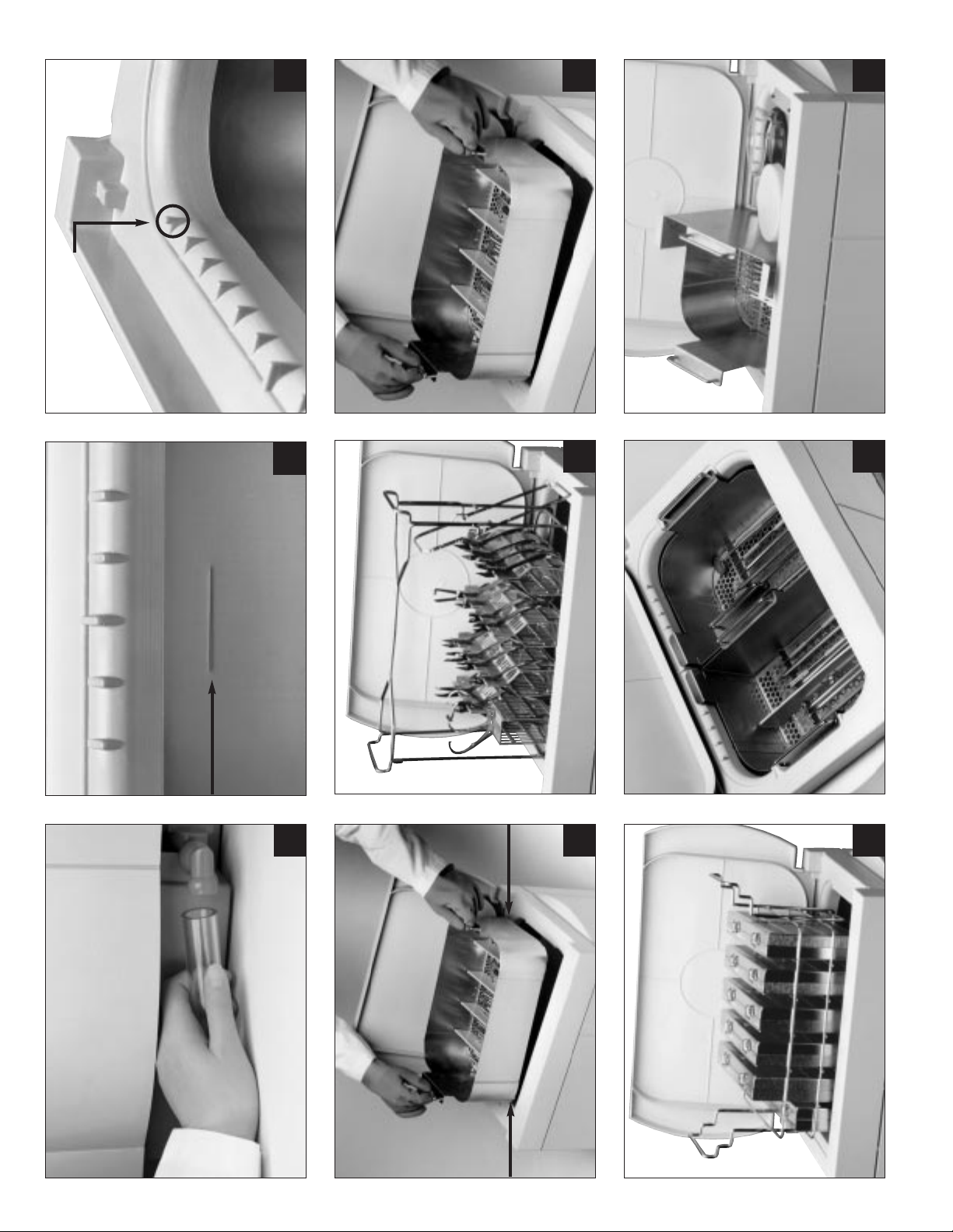
the draining tabs at opposite corners of the tank (Fig. 3, 4) and
allow the solution to drain off instruments.
IV. Cleaning Methods
A. InTank
1. The DDUS60P for use with Dentronix Vertical Plier Stands.
Slide up to four (4) large or up to eight (8) small Dentronix
Vertical Plier Stands into the “rails” on the bottom of the rack
(Fig. 5). The Plier Stands will be held in place during handling,
even when held at an angle. The handle on top of the rack
facilitates lowering and raising the rack into and out of the
tank, and is also equipped with a “kick stand” for draining on
the bezel of the unit.
2. The DDUS60K and DDUS60W for use with Instrument Basket
Cleaning:
Place parts to be cleaned into the basket. Then place the
basket directly into the main tank containing ultrasonic solution.
NOTE: Baskets are furnished with adjustable Section Inserts
(DDUS60I) to keep instrument set-ups separated by user or
procedure, eliminating sorting and speeding instrument
processing
(Fig. 6). Baskets are not recommended for the
cleaning of cutting instruments, and baskets are not
designed for use in the DDS5000 dry heat sterilizer. For more
information, contact Dentronix.
3. The DDUS60S for use with Instrument Cassette Cleaning:
Place loaded rack into tank containing ultrasonic cleaning
solution
(Fig. 7)
B. In Beaker (for specialized item cleaning):
Place item into a beaker (DDUS60B), add desired cleaning
solution (e.g. Dentronix DCR-2 Cement Remover) according to
the manufacturer’s directions. Place the beaker band around
the beaker so that the bottom 1/3 will be suspended in the main
bath. Suspend the beaker in the tank by using the beaker posi-
tioning cover (DDUS60C).
V. Accessory Use Directions
A. DDUS60P – DentronixVertical Plier Stand Rack
Slide up to four (4) large or up to eight (8) small Dentronix
Vertical Plier Stands into the “rails” on the bottom of the rack.
The Plier Stands will be held in place during handling, even
when held at an angle. The handle on top of the rack facilitates
lowering and raising the rack into and out of the tank, and is also
equipped with a “kick stand” for draining on the bezel of the unit.
B. DDUS60K –
Large hands-free FingerGuard™ Instrument Basket
Dentronix Large FingerGuard Instrument Basket cleans large
volumes of instruments and increases instrument processing
efficiency. The Large FingerGuard Instrument Basket comes with
five (5) adjustable Basket Section inserts, which help stabilize
Vertical Plier racks or sort scalers and such by set-up or type.
C. DDUS60W –
Twin hands-free FingerGuard™ Instrument Basket
The Twin FingerGuard Basket provides you with the versatility of
cleaning two basket loads of instruments or basket and beaker
cleaning simultaneously. Place Twin FingerGuard Baskets side by
side, or use one basket with beaker positioning cover (DDUS60C)
(Fig. 8, 9). Twin FingerGuard Baskets may be used with or without

Owners Guide 5
Basket Section Inserts. Place instruments across ridges in bottom
of basket. Place basket in tank and clean for desired time.
D. DDUS60I – Basket Section Inserts
Place the “H” shaped Section Supports into the holes of the
raised ridge on the bottom of the basket. The tapered end
should be pointing up. Insert the flat Basket Section inserts into
the slots of the “H” shaped supports. For optimum stability, place
the supports at equal distance from the basket walls.
E. DDUS60C – Beaker Positioning Cover
Place the Beaker Positioning Cover on bezel. Place rubber ring
around the beaker so that at least 1/3 of the beaker is suspended
in the main bath. Clean for desired time. To reduce aerosols, place
white plastic beaker cover over the beaker during operation.
F. DDUS60S –
Hu-Friedy IMS(1) /Thompson(2) Instrument Cassette Racks
This rack will hold three (3) large or six (6) small cassettes. Up
to three (3) large cassettes may be placed horizontally in each
of the three tiers of the rack. Up to six (6) small cassettes can be
placed either horizontally or vertically in the rack. Place filled
rack in tank containing Dentronix solution. Once cassette
contents or instruments are cleaned, remove rack from tank and
tilt back over tank to drain (rack has stops on the back to prevent
the cassettes from sliding out (Fig. 7). Rinse rack and cassettes
on all sides thoroughly under running tap water. Place rack on
draining tabs of unit bezel to dry. (See Instrument Draining
section (III-D) for more details.)
(1) a registered trademark of Hu-Friedy Inc.
(2) a registered trademark of Thompson Inc.
VI. Environmental Conditions
• Intended for indoor use.
• Maximum altitude 2000m.
• Temperature range 5°C to 40°C.
• Maximum relative humidity 80% for temperatures up to 31°C,
decreasing linearly to 50% relative humidity at 40°C.
• Mains supply voltage fluctuations not to exceed 10% of the
nominal voltage.
• Transient over voltages category II.
• Pollution degree 2.
• Class I equipment.
VII. Warnings
• Do not operate the unit without sufficient solution in the tank.
• Do not use water alone as the carrier bath. Water is not a
satisfactory coupling agent unless a wetting agent is used.
For best results, use Dentronix DMP-US+Cleaner solutions.
• Do not place objects directly on bottom of the tank. They may
block cavitation, cause heat buildup in the transducer and
premature failure. Use accessory baskets, cassette racks or
beaker positioning cover to hold items.
• Do not use flammable liquids with Dentronix units.
• Do not restrict air flow. Provide adequate ventilation.
• Do not use acids in the stainless steel tank.
• Do not subject unit to shock or impact.
• Do not immerse the unit in water.
• Keep unit covered to reduce aerosols.
• Unspecified or improper use of this product may impair
safety protection.
• This equipment generates, uses, and can radiate radio
frequency energy and if not installed and used in accordance
with the instruction manual, may cause interference to radio
communications. It has been tested and found to comply with
the limits for an ultrasonic cleaner pursuant to Subpart C of
Part 18 of FCC Rules, which are designed to provide reason-
able protection against such interference when operated in
accordance with these instructions. Operation of this equip-
ment in a manner inconsistent with this manual is likely to
cause interference in which case the user, at his own expense,
will be required to take whatever measures may be required
to correct the interference.
VIII. Order Information
A. Units
Cat. No. Description Contents
DDUS60-115 Unit (115V, 50/60Hz) 1
DDUS60-230CE Unit (230V, 50/60Hz) 1
DDUS60R-115 Unit (115V, 50/60Hz) 1
DDUS60R-230CE Unit (230V, 50/60Hz) 1
B. Accessories:
DDUS60K Large hands-free FingerGuard
Instrument Basket 1
DDUS60W Twin hands-free FingerGuard
Instrument Basket 1
DDUS60P Dentronix Plier Stand Rack 1
DDUS60S Cassette Rack for Hu-Friedy IMS/
Thompson cassettes 1
DDUS60C Two-Beaker Positioning Cover 1
DDUS60I Basket Section Inserts 2
DDUS60F Replacement Drain Filters 3
DDUS60H Drain Hose 1
DDUS60B 600ml Borosilicate Beaker with
Cover and Rubber Ring 1
C. Ultrasonic Cleaning Solutions:
DMP-US+Super Concentrate General Purpose Ultrasonic
Cleaning Solution Concentrate in 8oz. (236ml)
Meter Dose Dispensing Bottle
D-CR2 Ultrasonic Cement Remover Concentrate in 8oz.
(236ml) Meter Dose Dispensing Bottle
IX. Unit Specifications
DDUS60 Countertop model
Tank capacity 4.8 gallons (18.3 liters)
Use capacity 4.0 gallons (15.2 liters)
Power 400 watts max
Operating frequency 40 kHz
100-115V Fuse T8A/250V, 5x20mm
230-240V Fuse T4A/250V, 5x20mm
Tank dimensions 14.0" x 9.0" x 8.75"
(35.6 x 22.9 x 22.2cm)
Overall dimensions 19.0" x 12.25" x 14.0"
(31.1 x 48.3 x 35.6cm)

6Dentronix Ultrasonic Cleaner
DDUS60R Recessed model
Tank capacity 4.8 gallons (18.3 liters)
Use capacity 4.0 gallons (15.2 liters)
Power 400 watts max
Operating frequency 40 kHz
100-115V Fuse T8A/250V, 5x20mm
230-240V Fuse T4A/250V, 5x20mm
Tank dimensions 14.0" x 9.0" x 8.75"
(35.6 x 22.9 x 22.2cm)
Above countertop 17.125" x 12.125" x 2.25"
(43.5 x 30.8 x 5.7cm)
Below countertop 17.125" x 13.0" x 14.0"
(43.5 x 33.0 x 35.6cm)
Electronic enclosure 17.0" x 7.5" x 4.5"
(43.2 x 19.0 x 11.4cm)
Complies with the MDD93/42/EEC
ISO 3864, No. B.3.1
Caution (refer to accompanying documents)
ISO 3864, No. B.3.6
Caution, risk of electric shock
C-UL-US listing is for the following catalog number
items only: DDUS60-115, DDUS60R-115
417-IEC-5016-a
Fuse location
X. Maintenance and Service
A. Cleaning
All components should be cleaned each day by wiping with a
soft cloth moistened with a commercially available mineral
deposit remover. Follow by cleaning with isopropyl alcohol or a
mild disinfectant. The stainless steel surfaces of the enclosures
should be cleaned with a stainless steel cleaner or isopropyl
alcohol when needed. Do not use phenolic based cleaners on
the electronics enclosure (DDUS60R only).
CAUTION: Do not use petroleum based solvents, iodophors or
phenolic based products. (Iodophors and phenolics can stain
the surface of the unit.) Clean up all liquid spills immediately.
B Inspecting the Power Cord
Periodically check the power cord for damage and see that the
connectors at both ends of the cord are fully seated.
C. Changing the Fuse
1. Turn the main power switch to the “off” position.
2. Remove the power cord from the wall outlet first and then
from the power cord receptacle on the rear of the unit.
!
3. The fuse is held by a fuse drawer which is inserted into the
fuse holder. The fuse holder remains fixed to the
DDUS60/DDUS60R housing. The fuse drawer encircles the
fuse and allows the fuse to be removed from the fuse holder.
These parts are located directly next to the power cord
receptacle. To access the fuse in the 115V unit, insert a small,
flat blade screwdriver in the slot on the fuse drawer and pry
the drawer open. To access the fuse on the 230V unit,
depress the center tab on the fuse drawer and pull the
drawer open.
4. Remove the fuse from the fuse drawer.
5. Examine the fuse. If it is blown, replace with a fuse which
matches the fuse type listed under the unit specifications
section of this manual. If fuse appears to be in good condi-
tion and power is not activated when the main power on/off
switch is turned “on,” return the unit to Dentronix.
6. Slide the fuse back into the holder. To secure the fuse drawer,
simply push the drawer closed.
7. Make sure the main power switch is “off.” Plug the power cord
into the power cord receptacle on the rear of the unit. Then
plug the power cord into the wall receptacle.
D. Service
This unit must be serviced by an authorized Dentronix Service
Center and should always be shipped complete with tank
assembly and electrical control unit.
XI. Limited Warranty
This product has been carefully manufactured and has met strin-
gent quality assurance requirements. If, in normal use, it is found
defective in material or workmanship within a period of one year
from date of purchase, it will be repaired or at Dentronix’s option,
replaced. Tampering with any of the components, misuse, negli-
gence, alteration, water damage, accident, or lack of reasonable
or proper maintenance and care, will void this warranty.
THE FOREGOING IS IN LIEU OF ANY EXPRESSED OR
IMPLIED WARRANTIES, INCLUDING WITHOUT LIMITATION,
ANY WARRANTIES OR MERCHANTABILITY OR FITNESS
FOR USE.
DENTRONIX ASSUMES NO RESPONSIBILITY FOR ANY
INCONVENIENCE,LOSS,INJURY,OR DIRECT,INDIRECT,OR
CONSEQUENTIAL DAMAGE ARISING FROM THE POSSES-
SION OR USE OFTHE PRODUCT.
Any claim for damage or breakage in transit should be made at
once against the carrier. If factory service is required, be certain
to properly pack your equipment and return prepaid and insured
to the factory.
Dentronix is a division of Coltène/Whaledent Inc.
46
7 8 9
Draining
Tab Draining
Tab
5
12
Fill Line
3
Draining Tab


P/N 86674B
MANUFACTURER
Coltène/Whaledent Inc.
750 Corporate Drive
Mahwah, NJ 07430
Tel. 201-512-8000
Fax 201-529-2103
SOLD BY
Dentronix Inc.
101 Steamwhistle Drive
Ivyland, PA 18974
Tel. 215-322-4220
Fax 215-364-8607
AUTHORIZED
EU REPRESENTATIVE
Coltène Whaledent
Dentalvertriebs GmbH
Fischenzstraße 39
D-78462 Konstanz / Germany
Tel. +49-7531-1208-0
Fax +49-7531-27069
This product complies with
MDD/93/42/EEC
This manual suits for next models
1
Popular Other manuals by other brands

PTP Turbo Blankets
PTP Turbo Blankets Turbo Blanket Installation instructions manual

Aqua Medic
Aqua Medic Cubicus CF Operation manual

NEC
NEC NEC020513 Applications

Eneo
Eneo PLS-5308 Full manual

Kalamazoo
Kalamazoo KAL-OL-MB180 brochure

Painless Performance Products
Painless Performance Products 20110 installation instructions


Phoenix Gold
Phoenix Gold MS-250 user guide

Aston Global
Aston Global Langham SDR978 Installation and owner's manual

Aquadistri
Aquadistri SuperFish Aqua 20 Warranty and manual

Robinson
Robinson R-66 Series Lithium-Ion installation instructions

T&D
T&D RTR-601-130 user manual

aquaHabitats
aquaHabitats MicroHabitat 30 Instructions for use