DENTSPLY AUSTENAL ELECTROMATIC-4 User manual

ELECTROMATIC -4
INDUCTION CASTING MACHINE
Operations Manual
DENTSPLY Austenal
DENTSPLY International Inc.
570 West College Avenue
York, PA 17405-0872
1-800-243-1942
prosthetics. entsply.com
www. entsply.com
Customer Service: 1-800-243-1942
Equipment Repair: 1-800-645-4333
Printe in U.S.A. NPK1312 Rev. C (04/12)

IMPORTANT WARNING
The Electromatic - 4 has been built to provide the sa est possible operating conditions
consistent with the ability to per orm its intended casting unctions. However, the high
requency and voltage produced require certain precautions to be taken.
THIS MACHINE IS DESIGNED WITH SAFETY FEATURES TO PROTECT THE
OPERATOR AND MUST NOT BE MODIFIED IN ANY FORM. ONLY A QUALIFIED
PERSON SHOULD MAKE ANY REPAIRS OR ADJUSTMENTS. CALL DENTSPLY
PROSTHETICS' TECHNICAL SUPPORT FOR REPAIR RECOMMENDATIONS. FAILURE
TO OBSERVE THIS PRECAUTION MAY RESULT IN SEVERE RADIO FREQUENCY
BURNS OR ELECTRICAL SHOCK.
PERSONS WEARING PACEMAKERS SHOULD NOT BE ALLOWED TO OPERATE THE
UNIT AND IT IS ADVISABLE THAT SUCH INDIVIDUALS MAINTAIN A DISTANCE OF
10 FEET FROM THE OPERATING AREA.
Failure to observe this precaution may result in mal unction o the pacemaker while in
the vicinity o the machine and critical injury. Individuals who wear pacemakers should
be restricted rom the designated working vicinity o the machine. The Electromatic - 4
should not be operated in their presence.
Electromatic -
1

Important Warning . . . . . . . . . . . . . . . .1
Introduction . . . . . . . . . . . . . . . . . . . . . 3
Installation Preparations . . . . . . . . . . . . 4
Installation . . . . . . . . . . . . . . . . . . . . . . 5
Testing the Unit . . . . . . . . . . . . . . . . . . 10
Instrument and Control Description . . . .13
Trouble Shooting o Castings . . . . . . . .16
Speci ications . . . . . . . . . . . . . . . . . . .17
Maintenance . . . . . . . . . . . . . . . . . . . .19
Replacement Parts . . . . . . . . . . . . . . . .19
Electromatic -
2
TABLE OF CONTENTS

INTRODUCTION
The ELECTROMATIC - 4 has been esigne an built to consistently pro uce metallurgical soun precision
castings through a series of rigi ly controlle operations, automatically or manually performe . Casting with the
Electromatic - 4 consists of four basic operations:
1. Placing preheate crucible an mol in their appropriate hol ers
2. In uction melting of the alloy
3. Centrifugal casting of the molten alloy into the mol
4. Removal of the crucible an mol
Phases 2 an 3 are accomplishe through a complex electro-mechanical system. In uction melting is accomplishe
by creating a rapi ly alternating magnetic fiel , which causes the alloy in the crucible to absorb energy an
melt. The high frequency fiel is evelope in a water-coole coil, which surroun s the crucible an is pro uce
by a generator, which oscillates at approximately 500 kHz (thousan s of cycles per secon ).
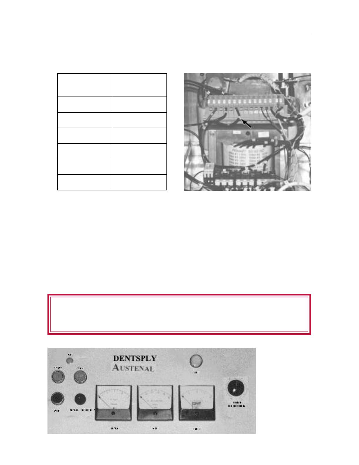
The START an STOP push buttons, the ON in icator an the circuit breaker form a circuit that will provi e
power to the Generator if the Melt Coil is in the UP an LOCK position, an to the Centrifuge Motor if the Melt
Coil is in the DOWN position. Pressing the START push button will latch the circuit, which will be in icate by the
ON in icator, if all the interlocks are operating normally. The circuit will automatically unlatch in the event of a
power failure. This minimizes the possibility of an acci ent if the power is su enly restore . If an overloa
occurs within the Melt Circuit uring the melting cycle, the overloa circuit will turn off an unlatch the operation.
Pressing the STOP push button will unlatch the circuit uring Melting or Centrifuging an iscontinue power to the
generator or the centrifuge motor correspon ingly. During the centrifuge operation the cover is locke an can
not be opene until the arm comes to a complete stop. With the unit in the Automatic mo e, control of the
casting temperature is maintaine by the Optical Ra iation Pyrometer. This etector senses both visible light an
infrare ra iation coming irectly from the alloy, or carbon insert. Its signal is fe to a soli state Temperature
Controller. When the molten alloy reaches a preset temperature, the power to the Melt Coil is cycle ON an
OFF, automatically maintaining the alloy at the selecte temperature prior to casting. This hol ing cycle is calle
“soaking”. Soaking times can be set from 0 to 60 secon s, an is engage by momentarily pressing the SOAK
TIMER ENGAGE push button uring melting or after the alloy has reache temperature. When the Soak Timer
completes the cycle an the Centrifuge Cover is close , the Melt Coil rops, the casting arm revolves clock-wise
an the molten alloy will be centrifugally cast into the mol . The centrifuge will spin for 30 secon s an
automatically stop. When the unit is use in the Manual mo e, control of the casting operation is epen ent on
the operator observing the alloy in the crucible an manually cycling the Start an Stop push buttons maintains
proper temperature. When the alloy is rea y to cast, place the investment ring in the cra le an close the
Centrifuge Cover. Continue to cycle the Start an Stop push buttons to maintain the esire casting temperature.
With the Start an Stop circuit latche , activate the Coil Release switch. This will rop the Melt Coil, the casting
arm will revolve an the molten alloy will be centrifugally cast into the mol . The centrifuge will spin for 30
secon s. When the centrifuge is in operation, in either Automatic or Manual mo e, the Coil Release Switch will
be inoperative until power to the centrifuge motor has been iscontinue .
Electromatic -
3

10 ”
28”
39”
WATER OUT
POWER CORD
40 A FUSES
220 V. 1 PHASE
WATER SUPPLY
WATER FILTER
WATER DRAIN
ALTERNATE WAT ER DRAIN
AREA FOR
E.C.M.
1 INCH SPACE
VALVE
REGULATOR
WATER IN
INSTALLATION: PREPARATION
The following outline has been arrange to provi e pertinent information relating to the installation, a justments
an testing of the Electromatic - 4. Strict a herence to these requirements will insure maximum epen able service.
Protect the unit from nearby furnace heat with a shield, if necessary.
FIG. 1
1. Customer will provi e essential electrical an water service for the unit.
A. See installation iagram.
B. Place unit where room temperature will never excee 122°F (50°C).
C. Unit shall not be expose to corrosive vapors or abrasive ust.
D. The rawing an following information will serve as a gui e for installation.
Installation of require utilities to comply with local co es.
Electromatic -
4
CAUTION:
Table of contents
Popular Test Equipment manuals by other brands

Redtech
Redtech TRAILERteck T05 user manual

Venmar
Venmar AVS Constructo 1.0 HRV user guide

Test Instrument Solutions
Test Instrument Solutions SafetyPAT operating manual

Hanna Instruments
Hanna Instruments HI 38078 instruction manual

Kistler
Kistler 5495C Series instruction manual

Waygate Technologies
Waygate Technologies DM5E Basic quick start guide

StoneL
StoneL DeviceNet CK464002A manual

Seica
Seica RAPID 220 Site preparation guide

Kingfisher
Kingfisher KI7400 Series Training manual

Kurth Electronic
Kurth Electronic CCTS-03 operating manual

SMART
SMART KANAAD SBT XTREME 3G Series user manual

Agilent Technologies
Agilent Technologies BERT Serial Getting started