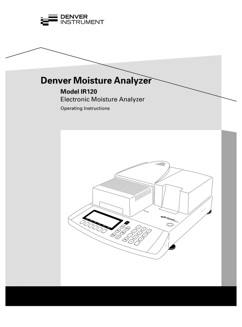
Denver Instrument IR-35 User manual

IR-35
Moisture Analyzer
Electronic Moisture Analyzer
Elektronischer Feuchtebestimmer
Operating Instructions/Betriebsanleitung

2
English – page 3
Deutsch – Seite 35

3
Intended Use Contents
The IR-35 moisture analyzer is intend-
ed for fast and reliable determination
of the moisture content of materials
of liquid, pasty and solid substances
using the thermogravimetric method.
Symbols
The following symbols are used in
these instructions:
●indicates steps you must perform
$indicates steps required only
under certain conditions
> describes what happens after you
have performed a particular step
– indicates an item in a list
!indicates a hazard
Intended Use 3
Warnings and Safety Information 4
Getting Started 7
General View of the Equipment 7
Equipment Supplied 8
Connecting the Moisture Analyzer
to AC Power 10
Leveling the Moisture Analyzer 12
Turning On the Analyzer; Opening
and Closing the Sample Chamber 13
Operating Design 14
Keys 14
Display 15
Configuration 16
Setting the Device Parameters 16
Setting the Drying Parameters 18
Operation 22
Example: Analysis with Specified
Drying Time 22
Adjusting the Analyzer 24
Heating Element Adjustment 24
Weighing System Adjustment 24
External Calibration and
Adjustment with a
Factory-Defined Weight 25
Interface Port 27
Pin Assignments 28
Error Codes 29
Care and Maintenance 30
Safety Inspection 32
Overview 33
Specifications 33
CMarking 34

4
Warnings and Safety Information
This moisture analyzer complies with
the European Council Directives as
well as international regulations and
standards for electrical equipment,
electromagnetic compatibility, and
the stipulated safety requirements.
Improper use or handling, however,
can result in damage and/or injury.
To prevent damage to the equipment,
read these operating instructions
thoroughly before using your IR-35
moisture analyzer. Keep these
instructions in a safe place.
Follow the instructions below
to ensure safe and trouble-free
operation of your moisture analyzer:
!Use the moisture analyzer only
for performing moisture analysis
on samples. Any improper use of
the analyzer can endanger persons
and may result in damage to the
analyzer or other material assets.
!Do not use this moisture analyzer
in a hazardous area; operate it only
under the ambient conditions
specified in these instructions.
!If you use electrical equipment in
installations and under ambient
conditions subject to stricter safety
standards than those described in
the manual, you must comply with
the provisions as specified in the
applicable regulations for installa-
tion in your country.
– The moisture analyzer may be
operated only by qualified persons
who are familiar with the proper-
ties of the sample to be analyzed.
!Make sure before getting started
that the voltage rating printed
on the manufacturer’s label is
identical to your local line voltage
(see “Connecting the Moisture
Analyzer to AC Power” in the
chapter entitled “Getting Started”).
– The analyzer comes with a power
supply that has a grounding
conductor.
– The only way to switch the power
off completely is to unplug the
power cord.
– Position the power cord so that it
cannot touch any hot areas of the
moisture analyzer.
– Use only extension cords that
meet the applicable standards
and have a protective grounding
conductor.
– Disconnecting the ground
conductor is prohibited.
– Connect only Denver accessories
and options, as these are optimally
designed for use with your
moisture analyzer.
Note on installation:
The operator shall be responsible
for any modifications to Denver
equipment or connections of cables
not supplied by Denver and must
check and, if necessary, correct
these modifications. On request,
Denver will provide information
on the minimum operating speci-
fications (in accordance with the
Standards listed on p. 34 for
defined immunity to interference).
– Protect the analyzer from contact
with liquid.
– If there is visible damage to the
equipment or power cord, unplug
the equipment and lock it in a
secure place to ensure that it can-
not be used for the time being.

5
Hazards for persons or equipment
posed by certain sample materials:
Fire Explosion
– Flammable or explosive
substances
– Substances that contain solvents
– Substances that release flammable
or explosive gases or vapors
during the drying process
In some cases, it is possible to
operate the moisture analyzer in an
enclosed nitrogen atmosphere to
prevent the vapor released during
drying from coming into contact
with oxygen in the surrounding
atmosphere. Check on a case-to-case
basis whether this method can be
used, because installation of the
analyzer in too small an enclosed
space can affect its functioning (for
instance, through excessive heat
build-up within the analyzer). When
in doubt, perform a risk analysis.
The user shall be liable and respon-
sible for any damage that arises
in connection with this moisture
analyzer.
!Clean your moisture analyzer
only according to the cleaning
instructions (see “Care and
Maintenance”).
Do not open the analyzer housing.
If the seal is broken, this will result
in forfeiture of all claims under the
manufacturer’s warranty.
If you have any problems with your
moisture analyzer:
Contact your local Denver office,
dealer or service center
Warning: Severe Burns!
– When setting up the moisture
analyzer, leave enough space to
prevent heat from building up
and to keep your analyzer from
overheating:
– leave 20 cm (about 8 inches)
around the moisture analyzer
– leave 1 m (3 ft.) above the
moisture analyzer
– Do not place any flammable
substances on, under or near the
moisture analyzer, because the
area around the heating unit will
heat up
– Be careful when removing a sam-
ple from the chamber: the sample,
the heating unit and the sample
pan may still be extremely hot
– Prevent excess heat build-up
around the analyzer

6
Poisoning Caustic burns
– Substances containing toxic or
caustic or corrosive components
may only be dried under a fume
hood. The value for the “lower
toxic limit” in a work area must
not be exceeded.
Corrosion:
– Corrosion may be caused by sub-
stances that release aggressive
vapors during the heating process
(such as acids).
We recommend working with only
small quantities of such samples,
to avoid build-up of vapors that can
condense on cold housing parts and
can cause corrosion.
The user shall be liable and respon-
sible for any damage that arises
in connection with this moisture
analyzer.

7
Getting Started
Pos. Designation
1 Hinged cover with heating
element
2 Leveling feet
3 On/off key
4 CF key (clear function; delete)
5 Enter key (confirm)
6 “Down/Back” key
7 ”Up/Forward” key
8 Print key
Pos. Designation
9 Disposable sample pan
10 Pan support
11 Pan draft shield
12 Display
13 Keypad
14 Interface port
15 Power socket
IR 35
1
2
2
3
4
5
6
7
8
9
10
11
12
13
14
15
General View of the Equipment

8
The moisture analyzer consists of a
heating unit, a weighing system, and
a display and control unit. In addition
to the socket for AC power (mains
supply), it also has an interface port
for connecting peripheral devices,
such as a computer, printer, etc.
Storage and Shipping Conditions
Allowable storage temperature:
0 to 40°C; 32 to 104°F
Do not expose the moisture analyzer
unnecessarily to extreme tempera-
tures, moisture, shocks, blows or
vibration.
Unpacking the Moisture Analyzer
After unpacking the equipment,
please check it immediately for any
visible damage
If any sign of damage is visible,
proceed as directed under “Safety
Inspection” in the chapter entitled
“Care and Maintenance.”
It is a good idea to save the box
and all parts of the packaging until
you have successfully installed
your equipment. Only the original
packaging provides the best protec-
tion for shipment. Before packing
your moisture analyzer, unplug all
connected cables to prevent damage.
Equipment Supplied
The equipment supplied includes the
components listed below:
– Moisture analyzer
– Power cord
– Pan support
– Pan draft shield
– 80 disposable aluminum sample
pans
– 1 pair of forceps
Installation Instructions
The IR-35 moisture analyzer is
designed to provide reliable results
under normal ambient conditions in
the laboratory and in industry. When
choosing a location to set up your
analyzer, observe the following so
that you will be able to work with
added speed and accuracy:
– Set up the moisture analyzer on
a stable, even surface that is not
exposed to vibrations, and level
it using the four leveling feet.
– Avoid placing the moisture
analyzer in close proximity to a
heater or otherwise exposing it
to heat or direct sunlight.
– Avoid exposing the moisture
analyzer to extreme temperature
fluctuations.
– Protect the moisture analyzer
from drafts that come from open
windows or doors.
– Keep the moisture analyzer
protected from dust, whenever
possible.
– Protect the moisture analyzer
from aggressive chemical vapors.
– Do not expose the equipment
to extreme moisture over long
periods.
– Make sure to choose a place where
excessive heat cannot build up.
Leave enough space between the
moisture analyzer and materials
that are affected by heat.

9
Conditioning the Moisture Analyzer
Moisture in the air can condense on the
surfaces of a cold moisture analyzer whenever
it is brought into a substantially warmer place.
If you transfer the moisture analyzer to a
warmer area, condition it for about 2 hours at
room temperature, leaving it unplugged from
AC power. Afterwards, if you keep the moisture
analyzer connected to AC power, the constant
positive difference in temperature between
the inside of the equipment and the outside
will practically rule out the effects of moisture
condensation.
Setting Up the Moisture Analyzer
Position the components listed below in the
order given:
– Pan draft shield
– Pan support
– Disposable sample pan

10
Connecting the Moisture Analyzer to AC Power
Check the voltage rating and the plug design
The heating element has been factory-set
to 230 V or 115 volts for technical reasons.
The voltage has been set as specified on
your order. The voltage setting is indicated
on the manufacturer’s label (see the back
of the analyzer), for example:
– 230 volts: IR35M-...230..
– 115 volts: IR35M-...115..
!If the voltage indicated on the label does
not match your local line voltage:
Do not operate your moisture analyzer;
contact your local Denver office or dealer.
Use only
– Original Denver power cords, or
– Power cords approved by a certified
electrician
– If you need to connect an extension cord,
use only a cable with a protective grounding
conductor
Connecting the moisture analyzer, rated to
Class 1, to AC power (mains supply): Plug the
power cord into an electrical outlet (mains sup-
ply) that is properly installed with a protective
grounding conductor (protective earth = PE)
Safety Precautions
If you use an electrical outlet that does not
have a protective grounding conductor, make
sure to have an equivalent protective conduc-
tor installed by a certified electrician as speci-
fied in the applicable regulations for installa-
tion in your country. Make sure the protective
grounding effect is not neutralized by use of an
extension cord that lacks a protective ground-
ing conductor.
Connecting Electronic Peripheral Devices
Make absolutely sure to unplug the analyzer
from AC power before you connect or discon-
nect a peripheral device (printer or PC) to or
from the interface port.

11
If you have a Class B digital device,
please read and follow the FCC
information given below:
“However, there is no guarantee that
interference will not occur in a parti-
cular installation. If this equipment
does cause harmful interference to
radio or television reception, which
can be determined by turning the
equipment off and on, the user is
encouraged to try to correct the
interference by one or more of the
following measures:
– Reorient or relocate the receiving
antenna.
– Increase the separation between
the equipment and receiver.
– Connect the equipment into an
outlet on a circuit different from
that to which the receiver is
connected.
– Consult the dealer or an experi-
enced radio/TV technician for
help.”
Before you operate this equipment,
check which FCC class (Class A or
Class B) it has according to the
Declaration of Conformity included.
Be sure to observe the information
of this Declaration.
NOTE: This equipment has been
tested and found to comply with
the limits pursuant to part 15 of FCC
Rules. These limits are designed
to provide reasonable protection
against harmful interference. This
equipment generates, uses and can
radiate radio frequency energy and, if
not installed and used in accordance
with these instructions, may cause
harmful interference to radio commu-
nications.
For information on the specific limits
and class of this equipment, please
refer to the Declaration of Confor-
mity. Depending on the particular
class, you are either required or
requested to correct the interference.
If you have a Class A digital device,
you need to comply with the FCC
statement as follows: “Operation of
this equipment in a residential area is
likely to cause harmful interference in
which case the user will be required
to correct the interference at his own
expense.”

12
Warmup Time
To deliver exact results, the moisture analyzer
must warm up for at least 30 minutes every
time you connect it to AC power or after a
relatively long power outage. Only after this
time will the analyzer have reached the
required operating temperature.
Leveling the Moisture Analyzer
Purpose:
– To compensate for unevenness at the place
of installation
– This is particularly important for testing
liquid samples, which must be at a uniform
level in the sample pan
Always level the moisture analyzer again any
time after it has been moved to a different
location.
Extend or retract the front and/or rear leveling
feet as needed to adjust the moisture analyzer
Installing the Aluminum Panels (Optional)
!To prevent burns, allow the glass panels
to cool sufficiently before removing them
!Do not handle the aluminum panels with
oily or greasy fingers
!Do not scratch the aluminum panels; do
not use abrasive or corrosive substances
to clean the aluminum panels
Remove the 2 rubber caps and the 2 screws
beneath them, and then remove the panel
retainer
Remove the glass panels
Position the aluminum panels in the retainer
Fasten the aluminum panels with the retainer
and screws; replace the 2 rubber caps
IR 35

13
Turning On the Analyzer; Opening and Closing
the Sample Chamber
To turn on the analyzer: press e
When opening or closing the sample chamber,
do not release the cover until it is in the fully
open or fully closed position

14
Operating Design
Operation of the moisture
analyzer follows a standard-
ized “philosophy” which is
described below. There is only
one key to a function; i.e.,
the key retains this function
throughout most of the menu
levels. The texts and symbols
shown always have the same
meaning.
Keys
Some of the keys trigger different functions, depending on whether you
press the key briefly or press and hold the key:
– Press briefly = hold the key down for less than 1.2 seconds
– Press and hold = hold the key down for more than 1.2 seconds
– If you press and hold longer than 1.2 seconds, the function triggered is
repeated every 0.6 seconds for as long as you hold the key.
Key Designation Press briefly Press and hold
eOn/off key Switch device on or off* —
cCF key Analysis: cancel function —
Menu: cancel selection
uEnter key Analysis: trigger the selected Menu: store the
function (e.g., tare) selected setting and
Menu: store the exit the menu
selected setting
yDown/Back Analysis: select a Menu: decrease
key function (e.g., tare) value 10-fold
Menu: decrease value
or return to previous
selection
xUp/Forward Analysis: select a Menu: increase
key function (e.g., tare) value 10-fold
Menu: increase value
or go to next selection
rPrint key Send readout value —
or data record over
the interface port
* When you switch off the moisture analyzer, it remains in the standby mode
IR 35

15
Busy symbol, plus/minus sign,
standby symbol:
The Jsymbol is shown here when
the moisture analyzer is processing
a function. The plus/minus sign
for the weight value or calculated
value appears here as well, and the
standby symbol when the device
is switched off.
Result:
This section shows the weight or
calculated value.
Unit:
When the weighing system stabilizes,
the unit of measurement for the
weight or calculated value is dis-
played here.
Graphic symbols:
Which symbol is shown here
depends on the operating status of
the analyzer. The examples below
indicate “Please close hood,” “Heat-
ing the sample” and “Please wait”
(hourglass).
Function line:
Press the Down/Back or Up/Forward
keys to move the focus and select
one of the functions shown here, and
the Enter key to activate the selected
function:
Display
The texts and symbols shown on
the display always have the same
meaning. The display is divided into
several areas.
Drying parameters:
The following symbols indicate
drying program parameters for infor-
mation, selection and configuration:
120°CTarget temperature
40min Drying time
AFully automatic
gWeight unit or unit
for a calculated value
AAnalysis start
2.0min Interval for automatic
output of intermediate
results
Adjustment function:
bAdjustment function
Drying parameters/Adjustment function
Busy symbol,
plus/minus sign,
standby symbol
Result
Unit
Graphic
symbols
Function line

16
Configuration
Setting the Device Parameters
o Factory setting
√User-defined setting
Setup 5. Interface 5.1 Baud rate 5.1.3 600 baud
Device 5.1.4 o 1200 baud
parame- 5.1.5 2400 baud
ters 5.1.6 4800 baud
5.1.7 9600 baud
5.1.8 19,200 baud
5.2 Parity 5.2.3 o Odd
5.2.4 Even
5.2.5 None
5.3 Number of 5.3.1 o 1 stop bit
stop bits 5.3.2 2 stop bits
5.4 Handshake 5.4.1 Software
mode 5.4.2 o Hardware
5.4.3 None
5.5 Number of 5.5.1 o 7 bits
data bits 5.5.2 8 bits
6. Printing 6.7 Printout 6.7.1 Result only
6.7.2 o Complete (with
GLP and drying
parameters)
6.9 Language 6.9.1 German
6.9.2 o English
6.9.3 US English (US
date/time format)
6.9.4 French
6.9.5 Italian
6.9.6 Spanish
6.9.8 Russian CP1251
6.9.9 Russian CP866
9. Reset menu 9.1 Factory 9.1.1 Reset to factory
settings settings
9.1.2 o Do not reset

17
Example
Changing the language to US mode (menu item 6.9.3)
Step Key (or instruction) Display
1. Select SET in the Repeatedly: x
function line
2. Confirm SET u5.
3. Select menu item 6 x6.
4. Open submenu u6.7
5. Select menu item 6.9 x6.9
6. Open submenu u6.9.2°
7. Select menu item 6.9.3 y6.9.3
8. Confirm menu item 6.9.3 u6.9.3°
9. Close the Setup menu Repeatedly: c
P˚
o
C
CAL SET PRG STARTEND
g
E
MS
/l
%
TAR
min min
A
P˚
o
C
CAL SET PRG STARTEND
g
E
MS
/l
%
TAR
min min
A

18
Setting the Drying Parameters
Select PRG in the function line to adapt parameters for the drying program to
the particular requirements of the product sampled.
Drying Parameters
Temperature during heating
40 to 160 oC
End of analysis
0.0 min Select 0.0 minutes for fully automatic shutoff
0.1 to 99 min Select an interval from 0.1 to 99 minutes to define
a specific analysis time
Display mode for result
%M Moisture
%S Dry weight
%MS Ratio
g Residual weight
Start of analysis
E With stability, after the ukey is pressed
A Without stability, after the cover is closed
Print intermediate results
0.0 min Off
0.1 to 10.0 min

19
Features
Temperature during heating
–Adjusted to defined specified
temperature during the analysis
process
Start of analysis
–With stability after the ukey
is pressed:
When START is shown in the
function line and you press u
to confirm, the initial weight is
stored at stability regardless of
whether the cover is open or
closed. Measurement begins as
soon as the cover is closed.
–Without stability after the cover
is closed:
A symbol shown in the graphic
symbol display prompts you to
close the cover once the initial
weight condition is met. The initial
weight is stored without stability
as soon as the sample chamber is
closed, and analysis begins.
End of Analysis with Shutoff
Parameters
–Fully automatic mode
–Timer mode
Fully automatic mode:
Use the fully automatic mode when
loss of weight on drying follows a
clearly delineated curve which can
be unambiguously evaluated (see
below).
Timer mode:
The analysis ends as soon as the
specified time has elapsed.
Display Mode for Result
The following units can be selected
for displaying analysis results:
–Moisture %M
–Dry weight %S
–Ratio %MS
–Residual weight g
Print Intermediate Results
Intermediate results can be printed
either at user-definable intervals or
by pressing the rkey.
Weight
Moisture (evaporation)
Automatic shutoff
Time

20
Example: setting the following drying parameters
Final temperature: 130°C
Start of analysis: without stability after the cover is closed
End of analysis: after 10 minutes
Display mode for result: moisture
Step Key (or instruction) Display
1. Turn on the analyzer eSelf-test runs
2. Select PRG: drying y
program parameters
3. Confirm PRG u105°C
(the previously set
temperature is displayed;
in this example, 105°C)
4. Set the heating xrepeatedly 130°C
temperature
(in this example: 130°C)
5. Confirm heating u0.0 min
temperature (the
previously set analysis
time is displayed; in
this example, 0.0 min)
6. Set the parameter for the xrepeatedly 10 min
end of analysis; in this
example, 10 minutes)
7. Confirm the “end of u
analysis”parameter
8. Select the result xor y%M
display mode (in this
example, moisture)
l
Table of contents
Languages:
Other Denver Instrument Measuring Instrument manuals
