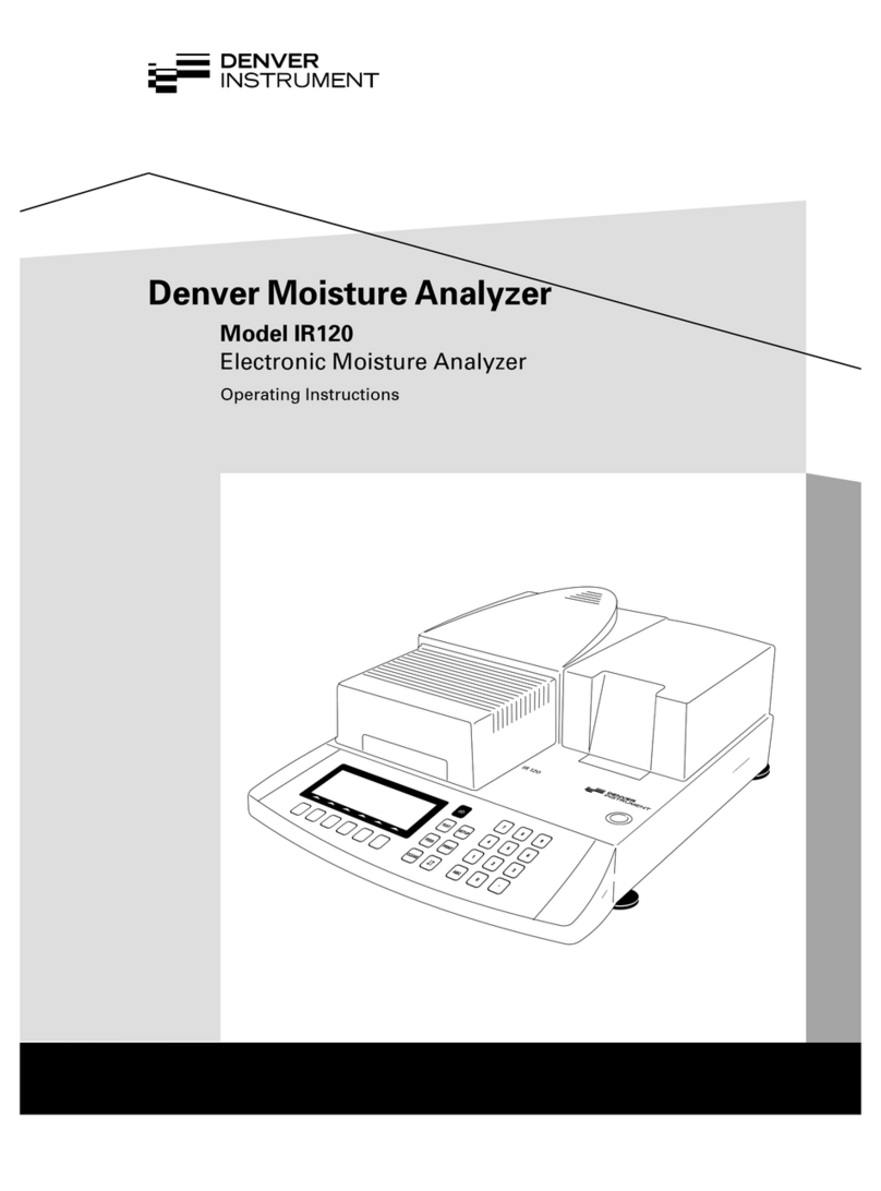
Denver Instrument IR-200 User manual

H
O
T
C
a
u
t
i
o
n
4 : 57 : 08 PM
3.48%
Denver Instrument
Operator: Dan
Sample ID # 138
Program): NonDairyCreamer
Denver Instrument
IR-200
4
123
56
789
•0
Test
Help
Zero
Paper
Feed
Denver Instrument Company
IR-200
Moisture Analyzer
Operation Manual
901119.1
Rev. F

You have purchased a quality precision weighing instrument that
requires handling with care.
Read entire contents of this Operation Manual prior to operating
your new Denver Instrument moisture analyzer.
Disclaimer Notice
“Calibrate your balance using the internal calibration weight or
a reference weight of the appropriate tolerance (class). An
instrument can be no more accurate than the standard to which
it has been compared. For assistance in the selection of refer-
ence weights, please contact the factory”.
Class A Digital Devices:
Notice: This equipment has been tested and found to comply
with the limits for a Class A digital device, pursuant to Part 15 of
the FCC rules. These limits are designed to provide reasonable
protection against harmful interference when the equipment is
operated in a commercial environment. The equipment gener-
ates, uses, and can radiate radio frequency energy and, if not
installed and used in accordance with the instruction manual,
may cause harmful interference to radio communications.
Operation of this device in a residential area is likely to cause
harmful interference in which the user will be required to correct
the interference at his own expense.
Caution!
Changes or modifications not expressly approved by the manu-
facturer could void the user’s authority to operate this equip-
ment.
Manufactured in the U.S.A. by:
Denver Instrument Company
6542 Fig Street • Arvada, Colorado 80004
(303) 431-7255 • (800) 321-1135 • Fax(303) 423-4831
!

Table Of Contents
Introduction . . . . . . . . . . . . . . . . . . . . . . . . . . . . . . . . . . . . . . . . . . . . . .1
Preparation . . . . . . . . . . . . . . . . . . . . . . . . . . . . . . . . . . . . . . . . . . . . . .2
Safety Precautions . . . . . . . . . . . . . . . . . . . . . . . . . . . . . . . . . . . . . . . . .2
Technical Specifications . . . . . . . . . . . . . . . . . . . . . . . . . . . . . . . . . . . .3
Help Feature . . . . . . . . . . . . . . . . . . . . . . . . . . . . . . . . . . . . . . . . . . . . . .3
Equipment Installation . . . . . . . . . . . . . . . . . . . . . . . . . . . . . . . . . . . . . .4
Pan Shield and Pan Support . . . . . . . . . . . . . . . . . . . . . . . . . . . . . . .4
Connecting to Power Source . . . . . . . . . . . . . . . . . . . . . . . . . . . . . .4
Connectors . . . . . . . . . . . . . . . . . . . . . . . . . . . . . . . . . . . . . . . . . . . . .5
Controls . . . . . . . . . . . . . . . . . . . . . . . . . . . . . . . . . . . . . . . . . . . . . . . .6
Display . . . . . . . . . . . . . . . . . . . . . . . . . . . . . . . . . . . . . . . . . . . . . . . . .6
Keypad . . . . . . . . . . . . . . . . . . . . . . . . . . . . . . . . . . . . . . . . . . . . . . . .7
Analyzer Operation . . . . . . . . . . . . . . . . . . . . . . . . . . . . . . . . . . . . . . . .8
Standby Mode . . . . . . . . . . . . . . . . . . . . . . . . . . . . . . . . . . . . . . . . . .8
Test Mode . . . . . . . . . . . . . . . . . . . . . . . . . . . . . . . . . . . . . . . . . . . . . .9
Recall . . . . . . . . . . . . . . . . . . . . . . . . . . . . . . . . . . . . . . . . . . . . . . . . .11
Setup Menus . . . . . . . . . . . . . . . . . . . . . . . . . . . . . . . . . . . . . . . . . . .13
Statistics . . . . . . . . . . . . . . . . . . . . . . . . . . . . . . . . . . . . . . . . . . . . . . .14
Develop . . . . . . . . . . . . . . . . . . . . . . . . . . . . . . . . . . . . . . . . . . . . . . .17
Units . . . . . . . . . . . . . . . . . . . . . . . . . . . . . . . . . . . . . . . . . . . . . . . . . .18
Slope . . . . . . . . . . . . . . . . . . . . . . . . . . . . . . . . . . . . . . . . . . . . . . . . .19
Standby Temperature . . . . . . . . . . . . . . . . . . . . . . . . . . . . . . . . . . . .20
System . . . . . . . . . . . . . . . . . . . . . . . . . . . . . . . . . . . . . . . . . . . . . . . .23
Printer . . . . . . . . . . . . . . . . . . . . . . . . . . . . . . . . . . . . . . . . . . . . . . . . .24
Sample Printouts . . . . . . . . . . . . . . . . . . . . . . . . . . . . . . . . . . . . . . . .26
Operator . . . . . . . . . . . . . . . . . . . . . . . . . . . . . . . . . . . . . . . . . . . . . .27
Sample Number . . . . . . . . . . . . . . . . . . . . . . . . . . . . . . . . . . . . . . . .28
Interval . . . . . . . . . . . . . . . . . . . . . . . . . . . . . . . . . . . . . . . . . . . . . . . .29
Clock . . . . . . . . . . . . . . . . . . . . . . . . . . . . . . . . . . . . . . . . . . . . . . . . .29
Interval . . . . . . . . . . . . . . . . . . . . . . . . . . . . . . . . . . . . . . . . . . . . . . . .30
Security . . . . . . . . . . . . . . . . . . . . . . . . . . . . . . . . . . . . . . . . . . . . . . .31
Clear Programs . . . . . . . . . . . . . . . . . . . . . . . . . . . . . . . . . . . . . . . . .33
Clear Data . . . . . . . . . . . . . . . . . . . . . . . . . . . . . . . . . . . . . . . . . . . .33
Conserve . . . . . . . . . . . . . . . . . . . . . . . . . . . . . . . . . . . . . . . . . . . . . .33
Program Transfer . . . . . . . . . . . . . . . . . . . . . . . . . . . . . . . . . . . . . . . .34
Beeper . . . . . . . . . . . . . . . . . . . . . . . . . . . . . . . . . . . . . . . . . . . . . . . .35
Operator . . . . . . . . . . . . . . . . . . . . . . . . . . . . . . . . . . . . . . . . . . . . . .35
Applications . . . . . . . . . . . . . . . . . . . . . . . . . . . . . . . . . . . . . . . . . . . . .37
Analytical Performance . . . . . . . . . . . . . . . . . . . . . . . . . . . . . . . . . . .39
Recommended Care . . . . . . . . . . . . . . . . . . . . . . . . . . . . . . . . . . . . .44
Printer Paper Installation . . . . . . . . . . . . . . . . . . . . . . . . . . . . . . . . . . .45
Troubleshooting . . . . . . . . . . . . . . . . . . . . . . . . . . . . . . . . . . . . . . . . . .46
Factory Defaults . . . . . . . . . . . . . . . . . . . . . . . . . . . . . . . . . . . . . . . . . .47
Accessories . . . . . . . . . . . . . . . . . . . . . . . . . . . . . . . . . . . . . . . . . . . . . .48
Warranty Information . . . . . . . . . . . . . . . . . . . . . . . . .Inside Back Cover
i

Declaration Of Conformity
Denver Instrument Company declares that the following products:
IR-200 Moisture Analyzer
conform to the European Union Council Directives and other stan-
dards listed below:
73/23/EEC, “Low Voltage Directive”
EN 61010-1, “Safety requirements for electrical equipment
for measurement, control, and laboratory use.
Part 1. General requirements”
89/336/EEC, “Electromagnetic Compatibility Directive”
EN 55011, Group 1, Class A, “Limits and methods of mea-
surement of radio disturbance characteristics
of industrial, scientific, and medical (ISM) radio-
frequency equipment”
EN 50082-1, “Electromagnetic compatibility - Generic
immunity standard; Part 1: Residential, com-
mercial, and light industry”
Further information may be obtained from the manufacturer, or from
the manufacturer’s representative:
manufacturer: manufacturer’s European represen-
tative:
Denver Instrument Company Denver Instrument Company, Ltd.
6542 Fig Street Denver house, Sovereign Way
Arvada, CO 80004 USA Trafalgar Business Park
Downham Market
Norfolk, UK PE38 9SW
Cautions and Warnings
Warning! - Prior to attempting to operate, read all accompany-
ing documents.
Risk of Shock! - Due to the electrical nature of this instrument, do
not attempt to disassemble unit. Contact Denver Instrument
Company Technical Support with any problems that arise.
High Temperature Parts - During operation use caution around
exhaust areas of the instrument.
!
ii

Introduction
Thank you for choosing the Denver Instrument Company IR-200 Moisture
Analyzer as your rapid moisture determination system. This state-of-the-
art, microprocessor based moisture/solids analyzer using the principle of
LOD (Loss On Drying). Samples are heated using infrared heat to liberate
moisture or other volatiles while continuously weighing the sample with
an integral precision electronic balance until endpoint conditions are
met. This unique product combines the performance and sophistication
of modern laboratory instrumentation in an analyzer designed for plant
floor operation.
Unpacking Instructions
Denver Instrument moisture analyzers are supplied in a boxed container.
Both the analyzer and the supplied accessories package are contained
in the box.
• Carefully unpack the carton.
• Check the contents of the box and verify that you have received the
following: • IR-200 Moisture Analyzer
• Operation Manual
• Pan Support
• Pan Shield
• Tweezers
• Disposable Sample Pans (1 pkg/50)
• Glass Sample Pads (1 pkg/25)
Lift up the printer over and you will find a roll of printer paper already
installed. Keep all parts of the packaging in a safe place. This packaging
guarantees the best possible protection for the transport of your moisture
analyzer. See instructions for repacking.
Except as noted in this manual, this analyzer contains no user ser-
viceable parts. Do not disassemble this unit. Unauthorized repair
attempts may void the warranty. For service or technical assis-
tance, call your distributor listed on the back cover of this manual.
Selecting the Location
Select a suitable work area which will allow your analyzer to work with
accuracy and dependability:
• This product is intended for indoor use.
• Area should be relatively free from drafts and vibrations.
• Surface should be rigid and level.
• Allow adequate ventilation ( at least one inch of free space on all
four sides of the analyzer).
• Do not locate near magnetic materials, or near equipment which
incorporate magnets in their design.
• Avoid areas which have variations in room temperature or have
excessive room temperature. Room temperature above 40°C/104°F
or below 15°C/59°F could affect the operation and accuracy of the
moisture analyzer.
1
Memo:
Note

2
Safety Precautions
Warning!
Use of this product in a manner not specified by the manufacturer may
impair any safety protection provided by the equipment!
Every attempt has been made to make this analyzer safe and easy to
use. However, like any laboratory instrument respect must be given to the
operation of the analyzer due to environmental conditions, the nature of
samples being tested and of the chemicals which might be near the
analyzer. To avoid personal injury or damage to the analyzer, please
observe the following precautions:
• Read all instructions in this Operations Manual prior to operating your
moisture analyzer.
Always use tweezers or tongs to remove the sample pan after comple-
tion of an analysis. The test sample and the pan are hot.
Do not touch the metal surfaces inside the drying chamber while remov-
ing or placing a sample into the analyzer since the surfaces are very hot.
Do not touch the heater hood ventilation dome at any time because it
will be very hot during and after the analysis.
• Do not test flammable or toxic materials.
• Use the analyzer in a fume hood if the samples emit fumes which could
be toxic, an irritant or corrosive.
• Know where the fire extinguisher is located. Use only an extinguisher
rated for use with electrical fires.
• Keep the analyzer clean. Always unplug the analyzer and cool it thor-
oughly before cleaning or servicing.
• Wear safety glasses, protective clothing and gloves.
• Do not block the ventilation dome on top of the heater hood.
• If necessary, press the TEST key during a test to abort the test. The ana-
lyzer will return to the Standby temperature and STANDBY screen.
• Locate the unit away from flammable materials. Allow at least 1” of
space around the unit.
!

Technical Specifications
Measurement method Infrared radiation and detection of weight
loss
Heat source Four parallel quartz infrared heaters
Temperature setting 30-210°C (86-410°F) in one degree increments
of Celsius
Temperature control Platinum temperature sensor, +/- 1°C with cali-
bration
Temperature steps Programmable one or two
Weighing pan (dia.) 100 mm (4 inches)
Balance capacity 100 grams
Balance readability 1 mg
Readability of results 0.01%
Working range 0.10 - 99.90 %
Units of results Percent moisture, solids, volatiles, moisture dry,
ppm and mg/l
End of analysis modes Time-out (max. 198 mins.), automatic slope
Display Backlit liquid crystal display, 30 characters by
8 lines
Controls Test, Zero, Paper Feed, Help, Enter and numer-
ic keypad
Program storage 99 programs with alphanumeric naming
Data storage 255 last results with statistical evaluation
Integral printer Thermal, 40 character graphical
External I/O One serial 25-pin bidirectional RS232C, and
One serial 9-pin uni-directional RS232C
Input Power 100 to 250 VAC 50/60 Hz 600 watts self adjus-
ing power supply
Fuse specifications Input - 2560V, 5A time-lag, type 3AG, 6.5mmm
diameter x 31.75mm length
Power Supply- 250V, 2A, quick acting, 5mm
diameter x 20mm length
Help Feature
The analyzer incorporates a Help feature unique to moisture analyzer
instrumentation. Help offers the user immediate, context-specific
advice on setup and operation. While lacking the level of detail possi-
ble in the operating instructions, help is conveniently available at the
touch of a key and is always “on the right page”. While becoming
familiar with the analyzer operation, the user is urged to explore and
use the broad range of help information offered.
Pressing the Help key produces a full-screen help message, with a
maximum of eight lines of text and thirty characters per line. If a help
message is being displayed, pressing any key immediately returns the
analyzer to its status when the Help key was pressed.
3

Installation
Pan Shield and Pan Support
Install the pan shield and pan support into the drying cham-
ber. Lift up the heater hood with the handle. Place the pan
shield so that the center hole fits over the center ring in the
base. Next, slip the stem of the pan support through the cen-
ter ring and into the pan receiver hole. The pan support which
holds the sample during testing should be level. This can be
checked by spinning the pan support.
Connecting to a Power Source
The moisture analyzer contains a universal self-adjusting power
supply rated from 100-250 VAC 50/60 Hz. Check that this volt-
age matches your local line voltage. If your voltage is not
within this rating, do not connect the power cord to the power
supply then contact your local distributor.
To connect the analyzer to a power source:
1. First insert the appropriate power cord into the power input
on the rear panel of the analyzer.
2. Then plug the power cord into a convenient wall socket.
3. To turn the analyzer ON, place the ON/OFF switch on the
back of the analyzer into the ON position (marked "1" on the
switch). The analyzer will proceed through a self-diagnostic
routine and then display the STANDBY Screen. If the analyzer
displays any diagnostic warning, consult the troubleshooting
section of this manual, or your local distributor.
4
Pan
Support
Pan
Shield
Air
Flow
Vents
Pan
Stem

Connectors
Power - Accepts the universal female end of the appropriate power cord.
Serial 1 - This input/output port supports a bi-directional RS232 interface via
a 25 pin, DB-25P type connector for intercommunication between two
moisture analyzers for the purpose of transferring drying procedures through
the PRG XMIT subroutine.
Serial 2 -This input/output port supports an uni-directional RS232 interface
via a 9 pin, DE-9S type connector. Any RS232 compatible device such as an
external printer can be connected to the analyzer.
Serial Characteristics
Connector: Serial bidirectional RS232C, 9 pin male subminiature D plug, DE-
9P uni-directional and a 25-pin bi-directional male subminature D plug DB-
25P (unspecified pins have no connectors)..
Pin
Call Out Function
1 case ground
2 serial data in
3 serial data out
4 CTS (Clear to Send)
5 RTS (Request to Send)
6 no connection
7 signal ground
8 no connection
9 no connection
Bidirectional Communication Number and alphanumeric entry
Key stroke assignments: require “Esc”
Start/Stop “R” Example:
Zero “Z” a) To enter Sample #: 1234,
Help “H” enter on commend line: 1234, Enter, Esc., Enter
Enter “Esc” b) To enter Program name: CORN,
Screen Status “*” enter on command line: Esc., CORN, Esc., Enter
Numeric: “1”, “2”,
“3”, “4”,“5”, “6”,“7”, “8”,“9”, “0”, “.”
Paper Feed “P”
5
4:57:08 PM
3.48% M
LCD
Display
Printer
Paper
Heater
Hood
Ventilation
Dome
Hood
Handle
Keypad
Printer
Cover

Controls
The following paragraphs briefly describe the location and functions of
all the analyzer controls. More detailed descriptions are provided in the
operations section of this manual.
Display
The moisture analyzer features a 1.5" x 5.25" (8 line by 30 character)
back lit liquid crystal display (LCD). This large, dot addressable LCD
allows the analyzer to convey a rich variety of detailed information in
plain English descriptive prompts, menus or help messages. There are
four different types of screens which will be displayed: STANDBY, TEST,
SETUP and setup entry screens. A title line on the top of every screen
identifies the specific screen displayed along with the date and time.
STANDBY - This screen will be displayed before and after a test. The
STANDBY Screen provides access to the Setup, Recall and Test modes.
TEST - This is a set of
screens which prompt
the operator through
testing a sample
including zeroing the
balance, adding
sample, getting the
initial weight, testing
and printing the result.
SETUP - Two setup
menu screens, SETUP
1 and SETUP 2, pro-
vide menu options of
all the available setup
subroutines for cus-
tomizing the analyzer
to the specific appli-
cation.
Setup entry Screens -
These screens which are sub-screens to the setup subroutines, guide
the operator through the entry or selection of specific desired choices.
At any point in these screens, pressing the “Help” key produces a full-
screen, context-sensitive help message supplying additional details and
guidance.
6
Denver Instrument
Test
Zero
Paper
Feed
Help
123
456
789
•0Enter
IR-200

Keypad
The analyzer features a sealed membrane keypad with numeric and
function keys as shown in the figure below. The keypad is best operat-
ed with a firm button press in the center of the key. With the beeper
setup option turned ON to either short (factory default) or long, an
audible beep will sound whenever a key has been pressed correctly.
Function keys include the following:
Zero - In the Standby mode allows the balance to be used as a
stand-alone 100 gram capacity to 1 mg resolution balance.
- In the Test mode, it can be used to rezero the balance if nec-
essary.
- On any screen which prompts for a numeric entry, it serves as
an erase key.
- In the Recall mode, it returns the screen to the first page of
programs.
Test - Initiates the test cycle to begin analyzing a sample.
- During a test, it serves as a stop key to abort a test in
progress.
– In the Recall subroutine, advances to the next page.
Paper - Key will feed the paper through the printer one line at a time.
Feed - In STATISTICS screen showing calculations, pressing this key will
print calculations.
- In the Recall mode, this key will activate a printout of all
stored programs.
- In the System subroutine, this key will print the system informa-
tion on the display.
Help - Causes display of context-sensitive “Help” messages provid-
ing details of current options available for the screen which
the key was pressed.
Enter - Causes the analyzer to accept entry of data keyed in by the
user in a setup entry screen.
- Used to accept the conditions on the screen when parame-
ter variables are present. The screen will then return to the
proceeding screen.
- Used to return to the proceeding screen when the display
shows a list of options.
- In the STATISTICS PRINT subroutine or Recall mode, this key will
stop the printing.
“.” - Used to enter numbers with a decimal point.
- In the Recall and STATISTICS subroutine, it advances to the
next page of choices.
7

Analyzer Operation
Standby Mode
After the self-diagnostic routine has been completed on power-up or
after a sample test has been completed, the analyzer goes into the
Standby mode. (Factory default is 60°C.) During standby, the tempera-
ture will go to the set standby temperature. The standby temperature is
set for each drying procedure in the Develop subroutine. While in the
Standby mode, the analyzer will display the STANDBY Screen. The ana-
lyzer will stay at the standby temperature until the Conserve mode
activates, turning OFF the heaters. The factory default for the Conserve
mode to turn OFF the heaters, is 60 minutes after the test. This can be
changed in the Conserve subroutine section described on page 33.
The STANDBY Screen will change to the CLOCK Screen when the
standby temperature turns off. The backlight of the LCD display will
also turn OFF automatically. The backlight OFF setting can be
changed in the Conserve subroutine. The default setting is 5 minutes.
The bottom line of the STANDBY Screen indicates the routines available
to the operator. In addition, the operator can always choose to test a
sample by pressing the Test key.
• Test - This routine is used to analyzer samples. On initial installation it
will use the Factory 1 program as the drying procedure. Otherwise, it
will use the last program which has been recalled in the Recall rou-
tine.
• Recall - This routine allow the operator to recall a stored drying pro-
cedure which has previously been saved. On initial delivery the unit
will have five factory default programs stored in program # one
through five. See Factory Default Settings screen on the following
page.
• Setup - This routine allows the operator to make changes to the ana-
lyzer including editing or developing new drying procedures, access-
ing stored data for printout or statistical evaluation, changing serial
interface parameters, setting date and time, formatting the results
printout, and many other parameters to customize the analyzer spe-
cific to an application or particular usage.
• Operator - This routine provides access for the user to select their
name from a list and will be included on the printout under operator.
Specific operator names must first be entered in the SETUP PRINTER,
CUSTOM subroutine.
8

1100::0000AAMMSSTTAANNDDBBYY1155NNOOVV0000
PPRRGG##0011FFAACCTTOORRYY11TTEEMMPP::6600CC
DDEENNVVEERRIINNSSTTRRUUMMEENNTTCCOOMMPPAANNYY
IIRR--220000MMOOIISSTTUURREEAANNAALLYYZZEERR
11>>RREECCAALLLL22>>SSEETTUUPP33>>OOPPEERRAATTOORR
9
In addition, several other functions are available from the STANDBY
Screen. Pressing the 0key displays the last test result on the TEST DONE
Screen. Pressing the Paper Feed key will print the last result and pressing
the Zero key displays the BALANCE screen.
Test Mode
Analyzing a sample on the moisture analyzer is intended to be simple
and rapid. However, to take full advantage of the performance and ver-
satility of the moisture analyzer the drying procedure should be optimized
for the sample material being tested and the analyzer settings estab-
lished for your conditions and objectives. To establish an optimized drying
procedure, see the Applications section of this manual or contact your
local distributor for assistance. To set up the analyzer to your specific
requirements, refer to the Setup Menus section, page 13.
Most samples can to tested for moisture using the Factory 1 default pro-
gram with reasonable results. However, if your distributor has tested your
sample and has developed an optimized drying procedure, you will first
want to establish a new program with these conditions as described in
the Develop subroutine section.
Standby Screen
TTeemmpp11==110055CC
TTiimmee11==OOFFFF
TTeemmpp22==OOFFFF
TTiimmee22==OOFFFF
SSllooppee==00..0055%%//11..00MMiinnuuttee
UUnniittss==MMooiissttuurree
SSttaannddbbyytteemmppeerraattuurree==6600CC
Factory 1 Default Settings

10
A. To test a sample, perform the following:
1). Open the heater hood using the handle on the front and place one
pan onto the pan support. Then close the heater hood.
2). At the STANDBY Screen, press the Test key. The display will change to
the SAMPLE ID Screen. (The Sample # prompt maybe turned OFF in
the Printer subroutine.)
3). Enter a sample ID with the number keys up to 16 digits and then press
the Enter key. (If a mistake is made on entry, pressing the Zero key will
erase the entry and allow a new entry.) The display will change to the
ZERO Screen showing zero grams and then prompt for the heater
hood to be opened and to add sample to the pan. (The Zero key is
functional if the balance should need re-zeroing.)
4). Open the heater hood. Begin adding sample. The display will show
the sample weight in grams. Close the heater hood when your
desired sample weight is reached. As the heater hood is closed, the
test will begin automatically and the display will change to the Test
screen. The TEST Screen will display the percent weight loss in the
selected units, the program # and name, the temperature and the
elapsed time. The printer will also begin printing the result report.
1100::0000AAMMSSAAMMPPLLEEIIDD1155NNOOVV0000
nnuummbbeerr::
eenntteerrssaammpplleennuummbbeerr
Sample ID Entry Screen
1100::0000AAMM1155NNOOVV0000
ooppeennhhooooddaannddaaddddssaammppllee
Weight Screen

11
5). The analyzer will process in determining the moisture in the sample
using the set drying procedure. When the endpoint condition is met,
the test will stop automatically. The Testing display will show the dry-
ing chamber temperature equilibrate at the set temperature.
To stop the test during analysis, press the Test key.
At the end of the test, the screen will change to the PRINT RESULT Screen.
After the result printout is completed, the display will return to the STAND-
BY Screen.
6). Raise the heater hood and carefully remove the hot sample with
tweezers or tongs.
Warning
The sample during and after analysis is hot. Remove sample with care.
Do not touch any internal part of the drying chamber or the dark grey
circular dome on the top of the drying chamber due to excessive heat.
Recall
Drying procedures can be stored as programs and then recalled to pro-
vide easy access to a procedure which is used frequently. This eliminates
having to reenter the test parameters to run a test. Up to 99 drying pro-
cedures can be stored. Creating and storing a new drying procedure is
described under the Develop subroutine. Each program is stored by
number, 1-99, and an alphanumeric program name (max. 19 charac-
ters). On initial setup, there will be 5 default programs stored under the
programs named Factory 1-5. Any or all of these programs can be delet-
ed by overwriting each with a newly developed program as described
in the Develop section.
1100::0000AAMMtteessttiinngg1155NNOOVV0000
##0011ffaaccttoorryy116655°°CC
00..0033%%MM
eellaappsseedd::00::1100
Test Screen
!
Memo:
Note

12
A. To recall a stored program, perform the following steps:
1). From the STANDBY Screen, press the 1key for Recall to access the
Recall routine. The screen will change and show the first page of
stored programs as shown below. Up to four programs are shown on
each screen.
2). To display programs on the next pages, press the “ . ” (decimal) key
for more. The next page of programs will be displayed each time the
“ . ” key is pressed.
3). If desired, press the Zero key to return to the first page of programs.
4). Press the number key next to the program to be recalled, then press
the Enter key. The analyzer will proceed to the STANDBY Screen and
use this program for the next test. The drying chamber temperature
will change to the newly recalled programs standby temperature.
As a shortcut, it is not necessary to have the program desired list-
ed on the display to recall it. Simply enter the desired program
number from the first page of listed programs and press the Enter
key.
B. To print a list of all stored drying procedures with the drying parame-
ters, perform the following:
1). From PROGRAMS Screen, press the Paper Feed key. The list of pro-
grams will be printed.
Pressing the Enter key will stop the printing.
1100::0000AAMMPPRROOGGRRAAMMSS1155NNOOVV0000
EENNTTEERRPPRRGG##
11>>FFAACCTTOORRYY11
22>>FFAACCTTOORRYY22
33>>FFAACCTTOORRYY33
44>>FFAACCTTOORRYY44
<<..>>NNEEXXTTPPAAGGEE
Recall Program Screen
Memo:
Note
Memo:
Note

13
Setup Menus
All changes to the analyzer are made in the Setup routine. Setup options
consist of two setup menus, SETUP 1 and SETUP 2, which lists the various
Setup options.
A. To enter the SETUP routine, perform the following:
1. From the Standby routine, press the 2key for SETUP. The display will
change to the SETUP 1 Screen as shown below.
An overview of each setup subroutine is described below:
• Statistics - A database of results which the operator can review stored
results, print all or selected results or perform statistical calculations of
all or selected results.
• Develop - Drying procedures can be developed by optimizing the dry-
ing parameters for specific applications.
• System - Provides a display or printout of important analyzer informa-
tion such as serial number, model and last calibration dates for both
the balance and heater.
• Calibrate - Procedure to calibrate the balance using a 50 gram weight.
• Printer - Allows customizing of the result printout including the activation
or deactivation of Operator, Sample ID and Custom 3 line alphanumer-
ic Header.
• Clock - For setting the time and date.
1100::0000AAMMSSEETTUUPP111155NNOOVV0000
11>>SSTTAATTIISSTTIICCSS66>>CCLLOOCCKK
22>>DDEEVVEELLOOPP77>>SSEERRIIAALL
33>>SSYYSSTTEEMM88>>SSEECCUURRIITTYY
44>>CCAALLIIBBRRAATTEE99>>SSEETTUUPP22MMEENNUU
55>>PPRRIINNTTEERR
Setup 1 Menu Screen
1100::0000AAMMSSEETTUUPP221155NNOOVV0000
11>>CCOONNSSEERRVVEE
22>>PPRRGGXXMMIITT
33>>BBEEEEPPEERR
99>>SSEETTUUPP11MMEENNUU
Setup 2 Menu Screen

14
• Serial - Allows set up of communication parameters for both serial
ports.
• Security - For activating or deactivating security protection of the ana-
lyzer.
• Conserve - Lets the operator control when the standby temperature
and backlight of the LCD display turn OFF.
• Prg Xmit - Allows the transfer of stored programs from one analyzer to
another.
• Beeper - Allows setting the audible tone to long, short or OFF.
B. To select a setup subroutine from the SETUP 1 menu, perform the follow-
ing:
1). Press the number key next to the setup subroutine to be selected. The
analyzer will proceed to the selected subroutine.
C. To select a setup subroutine from SETUP 2 menu, perform the following:
1). From the SETUP 1 Screen, press the 9key for SETUP 2 menu. The dis-
play will change to SETUP 2 menu.
D. To exit either SETUP 1 menu or SETUP 2 menu, perform the following:
1). Press the Enter key to exit. The analyzer will return to the STANDBY
Screen.
Statistics
The Statistics subroutine allows the analyzer to store the last 255 results
and to print or perform statistical calculations on all or selected results.
Data can be selected manually or automatically by date range, unit or
program #. Statistics include the count, average, standard deviation
(SD), relative standard deviation (RSD) and minimum and maximum val-
ues.
When the result memory is at full capacity (255 results), the analyzer will
automatically delete the oldest result as a new test is completed. Only
completed tests are added into the data storage. Therefore, a test
which has been stopped during analysis, will not be added to the data
storage. The Statistics subroutine is ON in the default factory setup.
However, statistics can be turned OFF, preventing data from being
stored. Statistics can be turned back ON when needed.

15
Definition of Statistics:
Count = the number of test results selected for statis-
tical evaluation
Average = Sum of test results/Count
Standard Deviation (SD) = Σ(X - X1)2
N-1
Relative Standard
Deviation (RSD) = Standard Deviation/Average x 100
Minimum = the smallest value of the selected test results
Maximum = the largest value of the selected test results
A. To enter the STATISTICS subroutine, perform the following:
1).Press the 1key for STATISTICS from SETUP 1 menu. The screen will display
the Statistics menu as shown:
B. To select results for statistical evaluation or printing of data, perform the
following:
1). Press the 1key for SELECT. The screen will display the Select menu.
1100::0000AAMMSSTTAATTIISSTTIICCSS1155NNOOVV0000
11>>SSEELLEECCTT66>>MMAANNUUAALL
22>>CCAALLCCUULLAATTEE
33>>PPRRIINNTTSSEELLEECCTTEEDDDDAATTAA
44>>EEXXPPOORRTTDDAATTAA
55>>SSTTAATTIISSTTIICCSS::OONN
DDaattaaEEnnttrriieess::4455
Statistics Menu Screen
1100::0000AAMMSSEELLEECCTT1155NNOOVV0000
11>>AALLLL66>>MMAANNUUAALL
22>>NNOONNEE
33>>UUNNIITTSS
44>>DDAATTEERRAANNGGEE99>>CCLLEEAARRDDAATTAA
55>>PPRRGG##
Select Menu Screen

16
2). Press the number key adjacent to the desired option:
1 key - for ALL to select all data results or
2 key - for NONE to deselect all data or
3 key - for UNITS to select data results by moisture, solids, etc. or
4 key - for DATE RANGE to select data tested between two dates or
5 key - for PRG # to select data tested using a particular program.
6 key - for MANUAL to selected data from the SELECT LIST Screen.
3). For ALL or NONE, the screen will immediately show the selecting
screen. For UNITS, DATE RANGE or PRG #, the screen will change to
an entry or selection screen to enter the desired selection criteria. The
display will return to the STATISTICS screen.
4). For MANUAL, the screen with show selection of number, status,
sequence number, date and result. Press the selection number to
toggle at ON or OFF. Use the " . " key to the next page or the Zero key
to returns to page 1. Pressing the 9key will toggle to the sample num-
ber field. After selecting data, press the Enter key to return to the STA-
TISTICS Screen.
C. To perform statistical calculations of selected results, perform the fol-
lowing:
1). Press the 2key for CALCULATE from the Statistics menu. The display will
change to STATS Screen showing the statistical calculations for the
selected results.
2). To print the statistical calculations, press the Paper Feed key, then
press the Enter key to return to the Statistics menu.
D. To print selected results, perform the following:
1). Press the 3 key from the Statistics Menu. The screen will show the PRINT
Screen and results will begin printing.
2). To stop the printing, press the Enter key.
E. To clear stored data results, perform the following:
1). Press the 1key for STATISTICS from SETUP 1 menu. The screen will dis-
play the Statistics menu.
2). Press the 9key for CLEAR DATA. The display will change to confirm the
selection.
3). Press the 1key to CLEAR ALL DATA or press the 2key to escape to the
Select menu without clearing data.
F. To turn statistics ON or OFF, perform the following:
1). Press the 5key for STATISTIC ON (or OFF). This prompt will change
depending if STATISTIC is OFF or ON. The screen will return to the SETUP
1 menu.
Table of contents
Other Denver Instrument Measuring Instrument manuals


