Desa RN30E-CAN Quick start guide

®
WARNING:Iftheinformationinthismanualisnotfollowed
exactly, a fire or explosion may result causing property
damage, personal injury, or loss of life.
— Donotstoreorusegasolineorotherflammablevapors
andliquidsin thevicinityof thisoranyotherappliance.
— WHAT TO DO IF YOU SMELL GAS
• Do not try to light any appliance.
• Do not touch any electrical switch; do not use any
phone in your building.
• Immediatelycall yourgas supplierfrom aneighbor’s
phone. Follow the gas supplier’s instructions.
• If you cannot reach your gas supplier, call the fire
department.
— Installation and service must be performed by a quali-
fied installer, service agency, or the gas supplier.
WARNING:Improperinstallation,adjust-
ment,alteration,service,ormaintenance
can cause injury or property damage.
Refertothis manualforcorrect installa-
tion and operational procedures. For
assistance or additional information
consult a qualified installer, service
agency, or the gas supplier.
Save this manual for future reference.
BLUE FLAME
VENT-FREE PROPANE AND NATURAL
GAS GREENHOUSE CO2 GENERATOR
OWNER’S OPERATION AND INSTALLATION MANUAL
WARNING: This is an unvented gas-
firedappliance.Itusesair(oxygen)from
the space in which it is installed. Provi-
sionsforadequatecombustionandven-
tilation air must be provided. Refer to
AirforCombustion and Ventilation
sec-
tion on page 3 of this manual.
WARNING: This appliance must not be washed. Use of a pressure washer, water or liquid cleaning
solution on this appliance can cause severe personal injury or property damage due to water and/or
cleaning solution:
• In electrical components, connections and wires causing electrical shock or component failure.
• On gas control components causing corrosion which can result in gas leaks and fire or explosion
from the leak.
Appliance must be cleaned without being subjected to liquid spray or excessive wetting.
This appliance is only for use with the type of gas indicated on the rating plate.
This appliance is not convertible for use with other gases.
This appliance is not for residential use.
DESA International • 2701 Industrial Drive • P.O. Box 90004 • Bowling Green, KY • 42102-9004
RN30E-CAN - Natural Gas
RP30E-CAN - Propane/LP Gas

2
105056
BLUE-FLAME VENT-FREE PROPANE/LP AND
NATURAL GAS GREENHOUSE CO2 GENERATOR
SAFETY
INFORMATION
WARNING ICON G 001
WARNINGS
IMPORTANT: Read this Owner’s
Manual carefully and completely
beforetryingtoassemble,operate,
orservicethisappliance.Improper
use of this appliance can cause
seriousinjuryordeathfromburns,
fire,explosion,electricalshock,and
carbon monoxide poisoning.
DANGER: Carbon monoxide
poisoning may lead to death!
Carbon Monoxide Poisoning: Early
signs of carbon monoxide poisoning re-
semble the flu, with headaches, dizziness,
ornausea.Ifyouhavethesesigns,theappli-
ance may not be working properly. Get
freshairatonce!Have applianceserviced.
Some people are more affected by carbon
monoxide than others. These include preg-
nant women, persons with heart or lung
diseaseoranemia,thoseundertheinfluence
of alcohol, and those at high altitudes.
Propane/LPandNaturalGas:Propane/
LP and Natural gas are odorless. An odor-
making agent is added to both gases. The
odor helps you detect a gas leak. However,
the odor added to these gases can fade. Gas
may be present even though no odor exists.
Make certain you read and understand all
Warnings. Keep this manual for reference.
It is your guide to safe and proper operation
of this appliance.
GENERALHAZARDWARN-
ING:Failuretocomplywiththe
precautions and instructions
provided with this appliance,
can result in death, serious
bodilyinjuryandpropertyloss
ordamagefromhazardsoffire,
explosion,burn,asphyxiation,
carbon monoxide poisoning,
and/or electrical shock.
If you need assistance or ap-
pliance information such as
aninstructionsmanual,labels,
etc.Contactthemanufacturer.
WARNING: Fire, burn, in-
halation, and explosion haz-
ard.Keepsolidcombustibles,
such as building materials,
paper or cardboard, feathers,
strawanddustasafedistance
away from the appliance as
recommended by the instruc-
tions.Neverusetheappliance
in spaces which contain or
may contain volatile or air-
borne combustibles, or prod-
ucts such as gasoline, sol-
vents, paint thinner, dust par-
ticles or unknown chemicals.
WARNING: Not for home
or recreational vehicle use
WARNING:Anychangetothis
appliance or its controls can be
dangerous.
1. This appliance is only for use with the
typeofgas indicated ontheratingplate.
Thisapplianceis not convertibleforuse
with other gases.
2. Do notplacepropane/LP supplytank(s)
inside any structure. Locate propane/
LP supply tank(s) outdoors.
3. If you smell gas
• shut off gas supply
• do not try to light any appliance
• do not touch any electrical switch;
do not use any phone in your building
• immediately call your gas supplier
from a neighbor’s phone. Follow the
gas supplier’s instructions
• ifyoucannotreach your gassupplier,
call the fire department
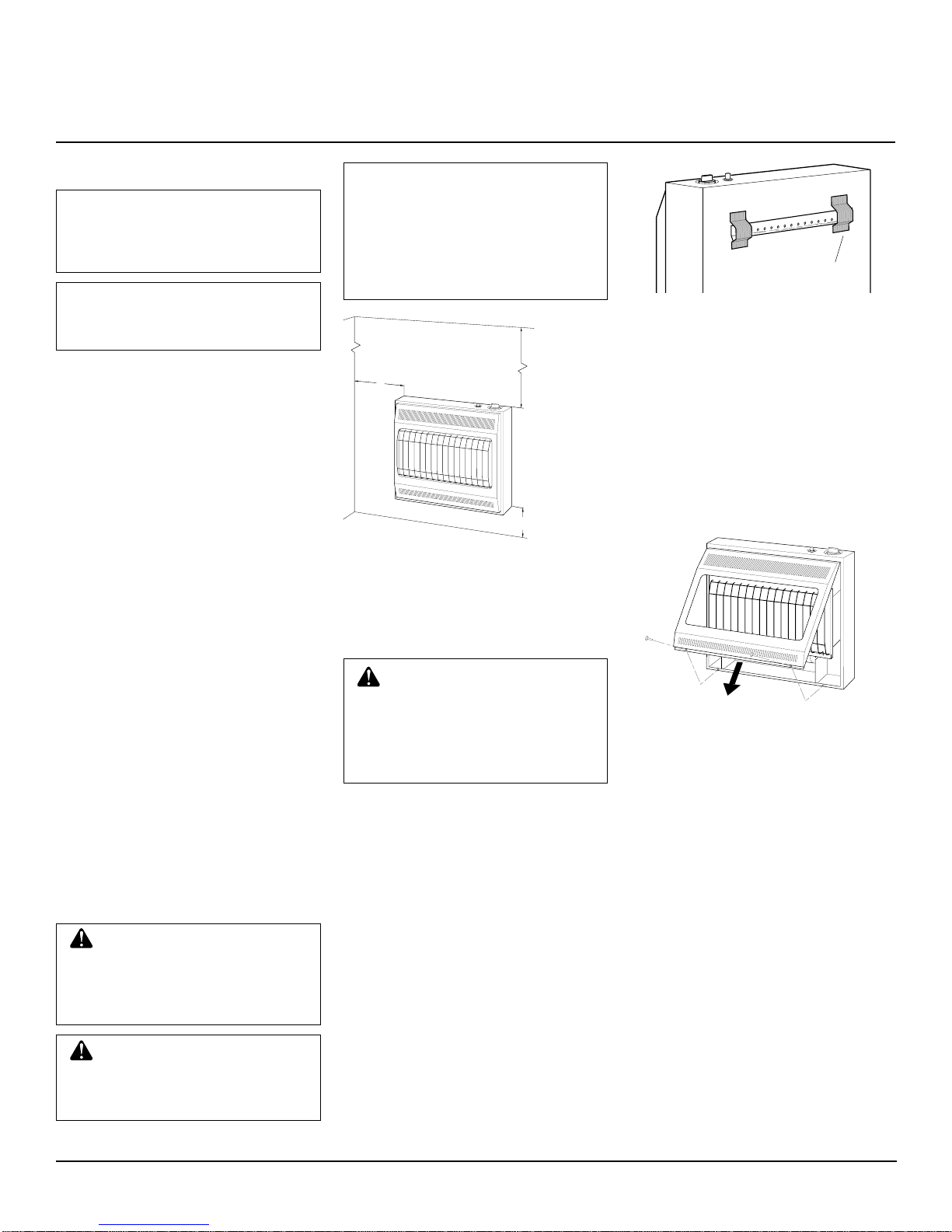
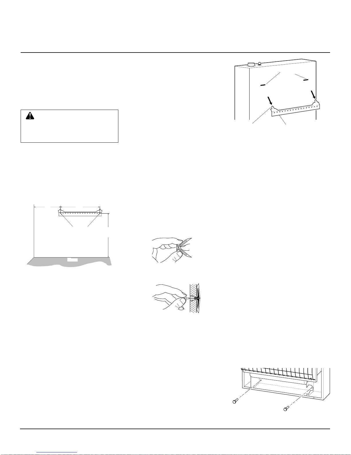
4. Never install the CO2 generator
• in a home
• in a recreational vehicle
• where flammable objects are less
than 36 inches from the front, top, or
sides of the appliance
• in high traffic areas
• in windy or drafty areas
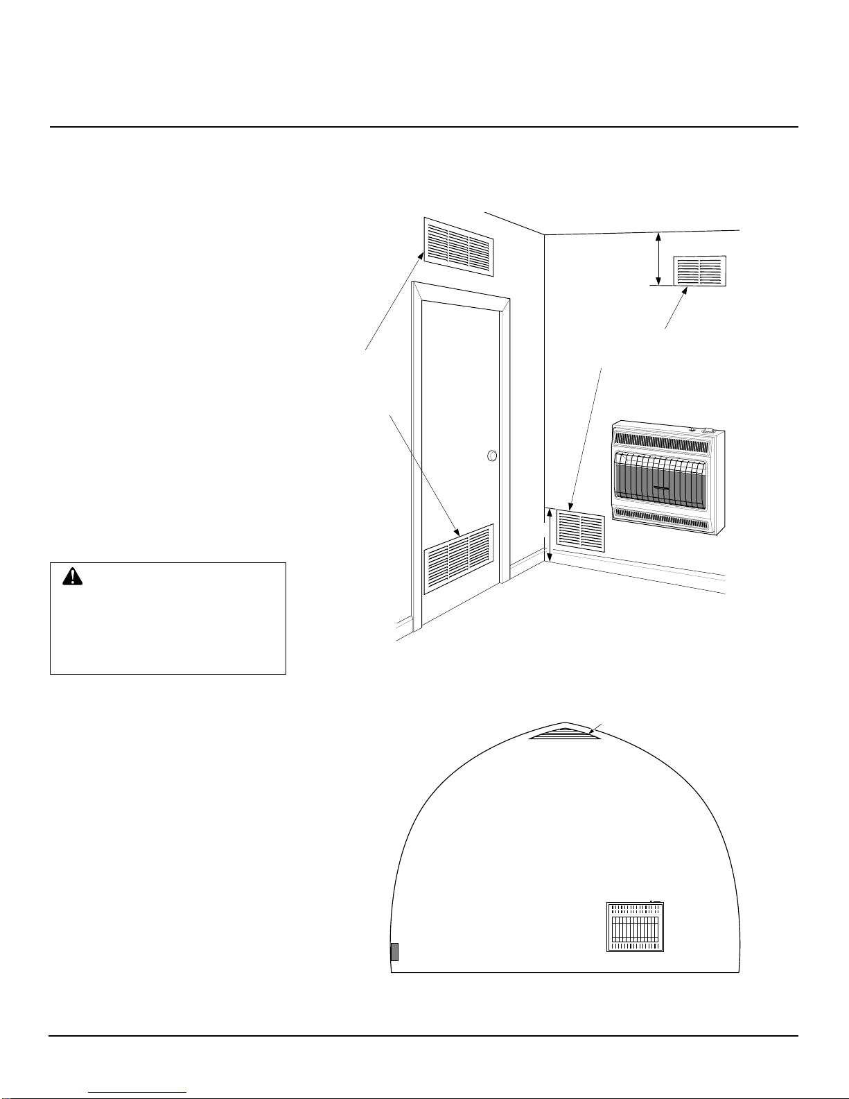
5. This appliance needs fresh, outside air
ventilation to run properly. This appli-
ance has an oxygen depletion sensor
(ODS) pilot light safety system. The
ODS shuts down the appliance if not
enough fresh air is available. See Air
for Combustion and Ventilation, pages
3 through 5.
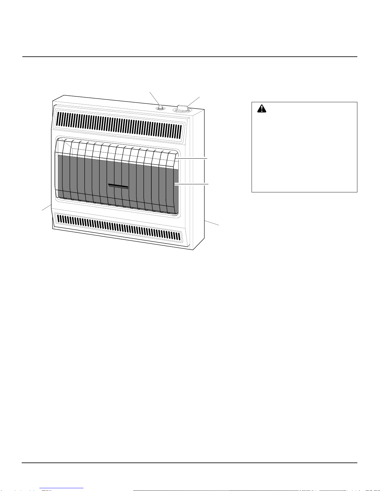
6. Keep all air openings in the front and
bottom of appliance clear and free of
debris. This will insure enough air for
proper combustion.
7. If appliance shuts off, do not relight
until you provide fresh, outside air. If
appliance keeps shutting off, have it
serviced.
8. Do not run CO2 generator
• where flammable liquids or vapors
are used or stored
• under dusty conditions
9. Never place any objects on the appli-
ance.
10. Surface of appliance becomes very hot
whenrunningappliance.Keep children
and adults away from hot surface to
avoid burns and clothing ignition. CO2
generator will remain hot for a time
after shutdown. Allow surface to cool
before touching.
11. Make sure grill guard is in place be-
fore running appliance.
12. Carefully superviseyoungchildrenwhen
they are in same area with appliance.
13. Do not use appliance if any part has
been under water. Immediately call a
qualified service technician to inspect
the appliance and to replace any part
of the control system and any gas con-
trol which has been under water.
14. Turn off appliance and let cool before
servicing. Only a qualified service per-
son should service and repair CO2
generator.
15. Operating appliance above elevations
of 4,500 feet could cause pilot outage.
16. To prevent performance problems, do
not use propane fuel tank of less than
100 lbs. capacity.
17. The CO2 generatorshouldbe inspected
at least annually by a qualified service
agency.
18. Do not operate appliance with front
panel removed.

3
105056
OWNER’S MANUAL
PRODUCT
IDENTIFICATION
Figure 1 - Vent-Free Propane/LP or Natural Gas Appliance
PRODUCT
FEATURES
Safety Device
This appliance has a pilot with an Oxygen
Depletion Sensor Shutoff System (ODS).
TheODS/pilotisarequiredfeatureforvent-
free CO2 generators. The ODS/pilot shuts
off the CO2 generator if there is not enough
fresh air.
Piezo Ignition System
ThisCO2generatorhasapiezoignitor.This
system requires no matches, batteries, or
other sources to light appliance.
UNPACKING
1. Remove CO2 generator from carton.
2. Remove all protective packaging ap-
plied to CO2 generator for shipment.
3. Check CO2 generator for any shipping
damage. If unit is damaged, promptly
inform dealer where you bought it.
LOCAL CODES
Installanduseappliancewithcare.Followall
localcodes.Intheabsenceoflocalcodes,use
the latest edition of National Fuel Gas Code
ANSI Z223.1, also known as NFPA 54* and
Canadian Gas Code B-149.1 and 2-M95,
Section 6.3 gas installation code
.
*Available from:
American National Standards Institute, Inc.
1430 Broadway
New York, NY 10018
National Fire Protection Association, Inc.
Batterymarch Park
Quincy, MA 02269
Ignitor Button Control Knob
Cabinet
Front
Panel
Heat Shield
Grill
Guard
AIR FOR
COMBUSTION AND
VENTILATION
PROVIDING ADEQUATE
VENTILATION
Unconfined Space
Can Gas Code B-149.1 and 2-M95, Section
6.3.3 states “An appliance installed for the
production of carbon dioxide in a green-
house may take its combustion air from
insidethegreenhousewhentherateofcom-
bustion does not exceed 20 Btuh per ft3 (0.2
kW per m3) of greenhouse volume and the
concentration of carbon monoxide in the
atmosphere does not exceed 35 ppm. The
concentrationofcarbon dioxide andcarbon
monoxide shall be verified upon initial
startup.
Confined Space
Ventilation air shall be supplied in accor-
dance with Can Gas Code B-149.1 and 2-
M95,Sections7.2and7.3and/orlocalcodes.
This CO2 generator is intended for installa-
tion in a greenhouse only.
This appliance shall not be installed in a
confined space or unusually tight construc-
tion unless provisions are provided for ad-
equate combustion and ventilation air.
Produce Storage Areas
Can Gas Code B-149.1 and 2-M95, Section
6.3.2 states “An appliance used in a produce
storage area shall take its combustion air
from outside the storage area”.
WARNING: This CO2 genera-
torshallnotbeinstalledina con-
finedspaceunlessprovisionsare
provided for adequate combus-
tion and ventilation air. Read the
following instructions to insure
properfreshairforthisandother
fuel-burning appliances in your
greenhouse.Installinaccordance
with
Can Gas Code B-149.1 and
2-M95, Section 6.3
Gas Installa-
tion Code and/or local codes.
Continued

4
105056
BLUE-FLAME VENT-FREE PROPANE/LP AND
NATURAL GAS GREENHOUSE CO2 GENERATOR
Continued
WARNING: If the area in which the CO2 generator may be operated is smaller than that defined as an
unconfined space or if the building is of unusually tight construction, provide adequate combustion and
ventilation air by one of the methods described in the
National Fuel Gas Code, ANSI Z223.1, 1992, Section 5.3,
Canadian Gas Code B-149.1 and 2-M95, Section 7.2 and 7.3,
or applicable local codes.
AIR FOR
COMBUSTION AND
VENTILATION
Continued
DETERMINING FRESH-AIR FLOW FOR APPLIANCE LOCATION
Determining if You Have a Confined or Unconfined Space
Use this worksheet to determine if you have a confined or unconfined space.
Space: Includes the room in which you will install appliance plus any adjoining rooms with doorless passageways or ventilation grills
between the rooms.
1. Determine the volume of the space (length x width x height).
Length x Width x Height = ____________________ cu. ft. (volume of space)
Example:
Space size 20 ft. (length) x 16 ft. (width) x 8 ft. (ceiling height) = 2560 cu. ft. (volume of space)
If additional ventilation to adjoining room is supplied with grills or openings, add the volume of these rooms to the total volume of
the space.
2. Divide the space volume by 50 cubic feet to determine the maximum Btu/Hr the space can support.
________________ (volume of space) ÷50 cu. ft. = (Maximum Btu/Hr the space can support)
Example:
2560 cu. ft. (volume of space) ÷50 cu. ft. = 51.2 or 51,200 (maximum Btu/Hr the space can support)
3. Add the Btu/Hr of all fuel burning appliances in the space.
CO2 generator ______________________ Btu/Hr
Gas water heater* ______________________ Btu/Hr
Gas furnace ______________________ Btu/Hr
Vented gas heater ______________________ Btu/Hr
Other gas appliances* +______________________ Btu/Hr
Total = ______________________ Btu/Hr
* Do not include direct-vent gas appliances. Direct-vent draws combustion air from the outdoors and vents to the outdoors.
4. Compare the maximum Btu/Hr the space can support with the actual amount of Btu/Hr used.
_____________ Btu/Hr (maximum the space can support)
_____________ Btu/Hr (actual amount of Btu/Hr used)
Example:
51,200 Btu/Hr (maximum the space can support)
70,000 Btu/Hr (actual amount of Btu/Hr used)
ThespaceintheaboveexampleisaconfinedspacebecausetheactualBtu/HrusedismorethanthemaximumBtu/Hrthespacecan support.
You must provide additional fresh air. Your options are as follows:
A. Rework worksheet, adding the space of an adjoining room. If the extra space provides an unconfined space, remove door to adjoin-
ing room or add ventilation grills between rooms. See Ventilation Air From Inside Building, page 5.
B. Vent room directly to the outdoors. See Ventilation Air From Outdoors, page 5.
C. Install a lower Btu/Hr appliance, if lower Btu/Hr size makes room unconfined.
If the actual Btu/Hr used is less than the maximum Btu/Hr the space can support, the space is an unconfined space. You will need no
additional fresh air ventilation.
Example:
Gas water heater 40,000 Btu/Hr
CO2 generator +30,000 Btu/Hr
Total =70,000 Btu/Hr

5
105056
OWNER’S MANUAL
Figure 2 - Ventilation Air From Inside Building If Applicable
Or
Remove
Door into
Adjoining
Room,
Option 3
Ventilation Grills
Into Adjoining Room,
Option 2
12"
12"
Ventilation
Grills
into Adjoining
Room,
Option 1
AIR FOR
COMBUSTION AND
VENTILATION
Continued
Outlet
Air
Inlet
Air
Figure 3 - Ventilation Air From Outdoors
Ventilation Air From Outdoors
Provide extra fresh air by using ventilation
grills or ducts. You must provide two per-
manent openings: one within 12" of the
ceiling and one within 12" of the floor.
Connecttheseitemsdirectlytotheoutdoors
orspacesopentotheoutdoors.Thesespaces
include attics and crawl spaces. Follow the
National Fuel Gas Code NFPA 54/ANSI
Z223.1,Section5.3,AirforCombustionand
Ventilation or Canadian Gas Code B-149.1
and 2-M95, Section 7.2 and 7.3 and/or appli-
cable local codes for required size of venti-
lation grills or ducts.
WARNING: Rework work-
sheet, adding the space of the
adjoiningunconfinedspace.The
combined spaces must have
enough fresh air to supply all
appliances in both spaces.
VENTILATION AIR
Ventilation Air From Inside
Building
Thisfreshairwouldcomefromanadjoining
unconfined space. When ventilating to an
adjoining unconfined space, you must pro-
vide two permanent openings: one within
12" of the ceiling and one within 12" of the
floor on the wall connecting the two spaces
(seeoptions1and2,Figure2).Youcanalso
remove door into adjoining room (see op-
tion 3, Figure 2). Follow the National Fuel
Gas Code NFPA 54/ANSI Z223.1, Section
5.3, Air for Combustion and Ventilation or
Canadian Gas Code B-149.1 and 2-M95,
Section 7.2 and 7.3 and/or applicable local
codes for required size of ventilation grills
or ducts.

6
105056
BLUE-FLAME VENT-FREE PROPANE/LP AND
NATURAL GAS GREENHOUSE CO2 GENERATOR
INSTALLING APPLIANCE TO
WALL
Mounting Bracket
The mounting bracket is located on back
panel of appliance. It has been taped there
forshipping.Removemountingbracketfrom
back panel.
Figure 5 - Mounting Bracket Location
Removing Front Panel Of CO2
Generator
1. Remove two screws near bottom cor-
ners of front panel.
2. Liftstraightupongrillguarduntilitstops.
Grill guard will slide up about 1/4".
3. Pull bottomoffront panel forward,then
down.
4. Remove cardboard packing from grill
and heat shield.
Figure 6 - Removing Front Panel Of CO2
Generator
Methods For Attaching
Mounting Bracket To Wall
Only use last hole on each end of mounting
bracket to attach bracket to wall. These two
holes are 16 inches apart from their centers.
Attach mounting bracket to wall in one of
two ways.
1. Attaching to wall stud
2. Attaching to wall anchor
Attaching to Wall Stud: This method
providesthestrongesthold.Insertmounting
screws through mounting bracket and into
wall studs.
AttachingtoWallAnchor: Thismethod
allows you to attach mounting bracket to
hollow walls (wall areas between studs) or
to solid walls (concrete or masonry).
Decidewhichmethodbettersuitsyourneeds.
Eithermethodwillprovideasecureholdfor
the mounting bracket.
Mounting
Bracket
CAUTION:
• appliance pilot and burner
must be at least 18 inches
above floor
• locate appliance where mov-
ing vehicle will not hit it
Forconvenienceandefficiency,installCO2
generator
• where there is easy access for operation,
inspection, and service
• where strong wind gusts from an open
door or ventilator can not blow directly
into appliance.
*16 3/4"
Figure4-MountingClearancesAsViewed
From Front of Appliance
INSTALLATION
NOTICE: A qualified service per-
son must install appliance. Fol-
low all local codes.
CHECK GAS TYPE
Only use gas type specified on rating plate.
Ifyourgassupply is different, do notinstall
appliance. Call dealer where you bought
appliance for proper type appliance.
INSTALLATION ITEMS
Before installing appliance, make sure you
have the items listed below.
• external regulator (Propane/LP Only,
supplied by installer)
• piping (check local codes)
• sealant (resistant to propane/LP gas)
• manual shutoff valve *
• ground joint union
• test gauge connection * (see Figure 13,
page 8)
• sediment trap
• tee joint
• pipe wrench
* An A.G.A. or C.G.A. design certified
manual shutoff valve with 1/8" NPT tap is
an acceptable alternative to test gauge con-
nection. Purchase the optional A.G.A. or
C.G.A.designcertifiedmanualshutoffvalve
fromyourdealer.SeeAccessories,page 15.
LOCATING APPLIANCE
Thisapplianceisdesignedtobemountedon
a wall.
Continued
WARNING:Maintainthemini-
mumclearancesshowninFigure
4.Ifyoucan,providegreaterclear-
ancesfromfloor,ceiling,andjoin-
ing wall.
WARNING: Never install the
CO2 generator
• in a home
• in a recreational vehicle
IMPORTANT:
Vent-freeCO2generatorsadd
carbon dioxide and moisture to the air.
36"
*
FLOOR
CEILING
Minimum
Minimum To Floor
6"
Minimum
From
Sides Of
Heater
Left
Side Right
Side
NOTICE:Theintendeduseofthis
applianceisthegenerationofcar-
bon dioxide inside greenhouses
for plant production.
• where flammable objects are
less than 36 inches from the
front,top,or sidesoftheappli-
ance
• in high traffic areas
• in windy or drafty areas

7
105056
OWNER’S MANUAL
INSTALLATION
Continued
Marking Screw Locations
1. Tape mounting bracket to wall where
appliance will be located. Make sure
mounting bracket is level.
WARNING:Maintainminimum
clearances shown in Figure 7. If
you can, provide greater clear-
ancesfromfloorandjoiningwall.
2. Mark screw locations on wall (see Fig-
ure 7).
Note:
Only mark last hole on each end
of mounting bracket. Insert mounting
screws through these holes only.
3. Remove tape and mounting bracket
from wall.
Figure 7 - Mounting Bracket Clearances
Attaching Mounting Bracket To
Wall
Note:
Wall anchors, mounting screws, and
spacers are in hardware package. The hard-
ware package is provided with appliance.
Attaching to Wall Stud Method
Forattachingmountingbrackettowallstuds
1. Drill holes at marked locations using
9/64" drill bit.
2. Place mountingbracketontowall. Line
uplastholeon each end of bracketwith
holes drilled in wall.
3. Insert mountingscrewsthrough bracket
and into wall studs.
4. Tighten screws until mounting bracket
is firmly fastened to wall studs.
Attaching to Wall Anchor
Method
For attaching mounting bracket to hollow
walls (wall areas between studs) or solid
walls (concrete or masonry)
1. Drill holes at marked locations using
5/16"drillbit.For solid walls (concrete
or masonry), drill at least 1" deep.
2. Fold wall anchor as shown in Figure 8.
3. Insert wall anchor (wings first) into
hole. Tap anchor flush to wall.
4. For thin walls (1/2" or less), insert red
key into wall anchor. Push red key to
“pop” open anchor wings.
IMPORTANT:
Do not hammer key!
Forthickwalls (over 1/2"thick)or solid
walls, do not pop open wings.
5. Place mountingbracketontowall. Line
uplastholeon each end of bracketwith
wall anchors.
6. Insert mountingscrewsthrough bracket
and into wall anchors.
7. Tighten screws until mounting bracket
is firmly fastened to wall.
Placing Appliance On Mounting
Bracket
1. Locate two horizontal slots on back
panel of appliance.
2. Place applianceontomounting bracket.
Slide horizontal slots onto stand-out
tabs on mounting bracket.
Figure 10 - Mounting Appliance Onto
Mounting Bracket
Figure 11 - Installing Bottom Mounting
Screws
Figure 8 - Folding Anchor
Figure 9 - Popping Open Anchor Wings
For Thin Walls
Stand-Out Tab Mounting Bracket
(attached to wall)
Horizontal Slots
Installing Bottom Mounting
Screws
1. Locate two bottom mounting holes.
These holes are near bottom on back
panel of appliance (see Figure 11).
2. Mark screw locations on wall.
3. Remove appliance from mounting
bracket.
4. Ifinstallingbottommounting screwsinto
hollowor solidwall, installwall anchors.
Follow steps 1 through 4 under Attach-
ing To Wall Anchor Method, column 1.
If installing bottom mounting screw
into wall stud, drill holes at marked lo-
cations using 9/64" drill bit.
5. Replace appliance onto mounting
bracket.
6. Place spacers between bottom mount-
ingholesandwallanchorordrilled hole.
7. Hold spacer in place with one hand.
With other hand, insertmountingscrew
through bottom mounting hole and
spacer. Place tip of screw in opening
of wall anchor or drilled hole.
8. Tighten both screws until appliance is
firmly secured to wall. Do not over
tighten.
Note:
Do not replace front panel at this
time. Replace front panel after making
gas connections and checking for leaks
(see pages 8 and 9).
32 1/2"
Min.
11"
Min. 16"
Adjoining Wall
Only Insert Mounting
Screws Through Last
Hole On Each End
Floor

8
105056
BLUE-FLAME VENT-FREE PROPANE/LP AND
NATURAL GAS GREENHOUSE CO2 GENERATOR
Figure 13 - Gas Connection
* An A.G.A. or G.G.A. design certified manual shutoff valve with 1/8" NPT tap is an
acceptable alternative to test gauge connection. Purchase the optional A.G.A. or G.G.A.
design certified manual shutoff valve from your dealer. See Accessories, page 15.
Installsedimenttrapinsupplylineasshown
in Figure 13. Locate sediment trap where it
is within reach for cleaning. Locate sedi-
menttrapwheretrapped matter is notlikely
to freeze. A sediment trap traps moisture
and contaminants. This keeps them from
going into appliance controls. If sediment
trap is not installed or is installed wrong,
appliance may not run properly.
IMPORTANT:
Hold pressure regulator
with wrench when connecting it to gas pip-
ing and/or fittings.
CAUTION:Usepipejointseal-
ant that is resistant to liquid pe-
troleum (LP) gas.
Typical Inlet Pipe Diameters
30,000 Btu/Hr models 1/2" or greater
CONNECTING TO GAS
SUPPLY
Propane/LPOnly:Theinstallermustsupply
anexternalregulator.Theexternalregulator
will reduce incoming gas pressure. You
must reduce incoming gas pressure to be-
tween 11 and 14 inches of water. If you do
not reduce incoming gas pressure, appli-
ance regulator damage could occur. Install
external regulator with the vent pointing
down as shown in Figure 12. Pointing the
vent down protects it from freezing rain or
sleet. Minimum inlet pressure shall be no
less than 11 inches of water.
NOTICE: A qualified service per-
sonmustconnectCO2generator
to gas supply. Follow all local
codes.
CAUTION: (Propane/LP Only)
Never connect appliance directly
to the propane/LP supply. This
appliance requires an external
regulator(notsupplied).Installthe
external regulator between the
applianceandpropane/LPsupply.
Figure 12 - External Regulator with Vent
Pointing Down (Propane/LP Only)
CAUTION: Use only new,
black iron or steel pipe. Inter-
nally-tinned copper tubing may
be used in certain areas. Check
yourlocalcodes.Usepipeof1/2"
diameter or greater to allow
proper gas volume to appliance.
If pipe is too small, undue loss of
pressure will occur.
INSTALLATION
Continued
External
Regulator
Propane/
LP Supply
Tank
Vent
Pointing
Down 3" Minimum
Tee Joint
Reducer Bushing
to 1/8" NPT
1/8" NPT Plug Tap
Test
Gauge
Connection *
Tee Joint
Pipe Nipple
Cap
Cabinet
Pressure
Regulator
3/8" NPT
Pipe
Nipple
Ground Joint
Union
Manual
Shutoff
Valve *
Propane/LP Only:
Typical Inlet
Pipe From
External Regulator
(11" W.C. to 14"
W.C. Pressure)
Sediment
Trap
Note:
Burner bracket
not shown for clarity
Continued
Natural Only:
Typical Inlet
Pipe From Gas
Meter
(4" W.C. to 10.5"
W.C. Pressure)
WARNING: Never connect
appliance to private (non-utility)
gas wells. This gas is commonly
known as wellhead gas.
NaturalGasOnly:
IMPORTANT:
Checkgas
linepressurebeforeconnectingapplianceto
gasline.Gaslinepressuremustbenogreater
than 10.5 inches of water. If gas line pres-
sure is higher, appliance regulator damage
could occur. Minimum inlet pressure shall
be no less than 4 inches of water.
Installation must include a manual shutoff
valve, union, and plugged 1/8" NPT tap.
Locate NPT tap within reach for test gauge
hook up. NPT tap must be upstream from
appliance (see Figure 13).
Apply pipe joint sealant lightly to male
threads. This will prevent excess sealant
fromgoinginto pipe. Excesssealantin pipe
could result in clogged appliance valves.

9
105056
OWNER’S MANUAL
ON
POSITION
OFF
POSITION
INSTALLATION
Continued
CHECKING GAS
CONNECTIONS
WARNING: Test all gas pip-
ing and connections for leaks
after installing or servicing. Cor-
rect all leaks at once.
WARNING:Neveruseanopen
flame to check for a leak. Apply a
mixture of liquid soap and water
toalljoints.Bubblesformingshow
a leak. Correct all leaks at once.
CAUTION: (Propane/LP Only)
Make sure external regulator has
been installed between propane/
LP supply and appliance. See
guidelines under
Connecting to
Gas Supply
, page 8.
Pressure Testing Gas Supply
Piping System
Note:
Pressuretesting shall beperformedin
accordance with Canadian Gas Code B-
149.1 and 2-M95, Section 5.22.
TestPressuresInExcessOf1/2PSIG
1. Disconnect appliance and its individual
manual shutoff valve from gas supply
pipingsystem.Pressuresinexcess of1/2
PSIG will damage appliance regulator.
2. Cap off open end of gas pipe where
manual shutoff valve was connected.
3. Pressurize supply piping system by ei-
therusingcompressedairoraninert gas.
4. Check all joints of gas supply piping
system. Apply mixture of liquid soap
and water to gas joints. Bubbles form-
ing show a leak.
5. Correct all leaks at once.
TestPressuresEqualToorLessThan
1/2 PSIG
1. Close manual shutoff valve (see Fig-
ure 14).
2. Pressurize supply piping system by ei-
therusingcompressedairoraninert gas.
3. Check all joints from propane/LP sup-
ply tank or main gas valve to manual
shutoff valve (see Figure 15). Apply
mixture of liquid soap and water to gas
joints. Bubbles forming show a leak.
4. Correct all leaks at once.
Pressure Testing Appliance Gas
Connections
1. Open manual shutoff valve (see Fig-
ure 14).
2. Open propane/LP supply tank valve
(Propane/LP Only) or main gas valve
(Natural Gas Only) located on or near
gas meter.
3. Make sure control knob of appliance is
in the OFF position.
4. Check all joints from manual shutoff
valve to control valve (see Figure 15).
Apply mixture of liquid soap and wa-
ter to gas joints. Bubbles forming show
a leak.
5. Correct all leaks at once.
6. Light appliance (see Operating CO2
Generator, page 10). Check the rest of
the internal joints for leaks.
7. Turn offappliance (seeTo Turn Off Gas
to Appliance, page 10).
8. Replace front panel.
Figure 14 - Manual Shutoff Valve
Manual
Shutoff
Valve
Closed
Open
Propane/
LP Supply
Tank
Control Valve
Location
Manual
Shutoff Valve
Control Valve
Location
Figure 15 - Checking Gas Joints
Gas Meter
Manual
Shutoff
Valve
NATURAL GAS
PROPANE/LP

10
105056
BLUE-FLAME VENT-FREE PROPANE/LP AND
NATURAL GAS GREENHOUSE CO2 GENERATOR
OFF
HIGH
PILOT
LOW
IGNITOR
OPERATING CO2
GENERATOR
FOR YOUR
SAFETY READ
BEFORE LIGHTING
WARNING: If you do not fol-
low these instructions exactly, a
fireorexplosionmayresultcaus-
ing property damage, personal
injury or loss of life.
A. Thisappliancehasapilotwhichmust
belightedby hand.Whenlightingthe
pilot, follow these instructions
exactly.
B. BEFORE LIGHTING smell all
aroundthe applianceareaforgas.Be
sureto smellnexttothefloorbecause
some gas is heavier than air and will
settle on the floor.
WHAT TO DO IF YOU SMELL
GAS
• Do not try to light any appliance.
•
Donottouch anyelectricswitch;do
not use any phone in your building.
• Immediatelycallyourgassupplier
from a neighbor’s phone. Follow
the gas supplier’s instructions.
• If you cannot reach your gas sup-
plier, call the fire department.
C. Useonlyyourhandto pushinorturn
thegascontrolknob.Neverusetools.
If the knob will not push in or turn
by hand, don’t try to repair it, call a
qualified service technician or gas
supplier. Force or attempted repair
may result in a fire or explosion.
D. Do not use this appliance if any part
has been under water. Immediately
call a qualified service technician to
inspect the appliance and to replace
any part of the control system and
any gas control which has been un-
der water.
LIGHTING
INSTRUCTIONS
1. STOP! Read the safety information
above.
2. Make sure manual shutoff valve is
fully open.
CAUTION: Do not try to ad-
just high/low level by using the
manual shutoff valve.
TO TURN OFF GAS
TO APPLIANCE
Shutting Off Appliance
1. Turncontrol knobclockwise
to the PILOT position.
2. Pressin controlknobandturnclock-
wise to the OFF position.
Shutting Off Burner Only (pilot
stays lit)
Turn control knob clockwise to
the PILOT position.
1. Remove front panel (see Figure 6,
page 6).
2. Followsteps1through5under Light-
ing Instructions.
3. With control knob pressed in, strike
match. Hold match to pilot until pi-
lot lights.
4. Keep control knob pressed in for 30
seconds after lighting pilot.After 30
seconds, release control knob.
5. Replace front panel.
MANUAL LIGHTING
PROCEDURE
Thermocouple Ignitor Electrode
Pilot Burner
Figure 16 - Control Knob In The OFF
Position
Ignitor Button Control Knob
Figure 17 - Pilot
3. Turncontrol knobclockwise
to the OFF position (see Figure 16).
4. Wait five(5)minutestoclearout any
gas. Then smell for gas including
near the floor. If you smell gas,
STOP! Follow “B” in the safety in-
formation at left. If you don’t smell
gas, go to the next step.
5. Pressin controlknobandturncoun-
terclockwise to the PILOT
position. Keep control knob pressed
infor five(5)seconds (see Figure16).
Note:
You may be running this ap-
pliance for the first time after hook-
ing up to gas supply. If so, the con-
trol knob may need to be pressed in
for 30 seconds. This will allow air to
bleed from the gas system.
• If control knob does not pop up
when released, contact a qualified
service person or gas supplier for
repairs.
6. With control knob pressed in, push
downand releaseignitor button.This
will light pilot. The pilot is attached
to the front of burner. The burner
and pilot are located behind the heat
shield. If needed, keep pressing igni-
tor button until pilot lights.
Note:
If pilot does not stay lit, refer
toTroubleshooting,pages12through
14. Also contact a qualified service
person or gas supplier for repairs.
Until repairs are made, light pilot
withmatch.Tolightpilot withmatch,
see Manual Lighting Procedure.
7. Keep control knob pressed in for 30
seconds after lighting pilot.After 30
seconds, release control knob.
Note:
If pilot goes out, repeat steps
3 through 7.
8. Turn control knob counterclockwise
to the LOW position. The
mainburnershouldlight. Set control
knobtoanylevelbetweenHIGH and
LOW. To turn control knob from
LOW to a higher setting, pressinthe
controlknoband turncounterclock-
wise .
Note:
Both HIGH and LOW are
locked positions. You must press in
control knob before turning it from
these positions.

11
105056
OWNER’S MANUAL
1/2 HEAT SHIELD
HEIGHT
INCORRECT FLAME PATTERN
AT HIGH POSITION
INSPECTING
BURNER
Check pilot flame pattern and burner flame
pattern often.
PILOT FLAME PATTERN
Figure 18 shows a correct pilot flame pat-
tern. Figure 19 shows an incorrect pilot
flame pattern. The incorrect pilot flame is
not touching the thermocouple. This will
cause the thermocouple to cool. When the
thermocouplecools,theappliance will shut
down.
If pilot flame pattern is incorrect, as shown
in Figure 19
• turn appliance off (see To Turn Off Gas
to Appliance,page 10)
•
seeTroubleshooting, pages12through 14
Figure 18 - Correct Pilot Flame Pattern
Figure 19 - Incorrect Pilot Flame Pattern
NOTICE: Do not mistake orange
flames with yellow tipping. Dirt
or other fine particles enter the
applianceandburncausingbrief
patches of orange flame.
Thermocouple Pilot Burner
Pilot Burner
Thermocouple
Figure 20 - Correct Burner Flame Pattern
Figure21-IncorrectBurnerFlamePattern
BURNER FLAME PATTERN
Figure 20 shows a correct burner flame
pattern.Figure21showsanincorrectburner
flame pattern. The incorrect burner flame
patternshowsyellowtippingoftheflame.It
also shows the flame higher than 1/2 the
heat shield height.
Ifburnerflamepatternisincorrect,asshown
in Figure 21
• turn appliance off (see To Turn Off Gas
to Appliance, page 10).
•
seeTroubleshooting, pages12through 14
WARNING: If yellow tipping
occurs,yourCO2generatorcould
produce increased levels of car-
bon monoxide. If burner flame
patternshowsyellowtipping,fol-
lowinstructionsatbottomofthis
page.
Yellow
Tipping
CLEANING AND
MAINTENANCE
WARNING:Turnoffappliance
and let cool before cleaning.
CAUTION:Youmustkeepcon-
trolareas,burner,andcirculating
air passageways of appliance
clean. Inspect these areas of ap-
pliance before each use. Have
CO2 generator inspected yearly
byaqualifiedserviceperson.Ap-
pliance may need more frequent
cleaning due to excessive saw-
dust, cobwebs, etc.
ODS/PILOT AND BURNER
• Use a vacuum cleaner, pressurized air, or
small, soft bristled brush to clean.
CABINET
Air Passageways
• Use a vacuum cleaner or pressurized air
to clean.
Exterior
• Use a soft cloth dampened with a mild
soap and water mixture. Wipe the cabi-
net to remove dust.
CORRECT FLAME PATTERN
AT HIGH POSITION
1/2 HEAT SHIELD
HEIGHT

12
105056
BLUE-FLAME VENT-FREE PROPANE/LP AND
NATURAL GAS GREENHOUSE CO2 GENERATOR
TROUBLESHOOTING
Note:
All troubleshooting items are listed
in order of operation.
WARNING: Turn off and
unplug appliance and let cool
before servicing. Only a quali-
fied service person should ser-
vice and repair appliance.
CAUTION: Never use a wire,
needle, or similar object to clean
ODS/pilot.ThiscandamageODS/
pilot unit.
OBSERVED PROBLEM
When ignitor button is pressed, there is no
spark at ODS/pilot
When ignitor button is pressed, there is
spark at ODS/pilot but no ignition
ODS/pilot lights but flame goes out when
control knob is released
Burner does not light after ODS/pilot is lit
POSSIBLE CAUSE
1. Ignitor electrode positioned wrong
2. Ignitor electrode broken
3. Ignitorelectrodenotconnectedto igni-
tor cable
4. Ignitor cable pinched or wet
5. Broken ignitor cable
6. Bad piezo ignitor
1. Gassupplyturnedofformanualshutoff
valve closed
2. Control knob not in PILOT position
3. Control knob not pressed in while in
PILOT position
4. Air in gas lines when installed
5. Depletedgassupply(Propane/LPOnly)
6. ODS/pilot is clogged
7. Gas regulator setting is not correct
1. Control knob not fully pressed in
2. Controlknobnotpressedinlongenough
3. Manual shutoff valve not fully open
4. Thermocoupleconnectionlooseatcon-
trol valve
5. Pilotflamenottouchingthermocouple,
which allows thermocouple to cool,
causing pilot flame to go out. This
problemcouldbecausedbyoneorboth
of the following:
A) Low gas pressure
B) Dirty or partially clogged ODS/
pilot
6. Thermocouple damaged
7. Control valve damaged
1. Burner orifice is clogged
2. Burner orifice diameter is too small
3. Inlet gas pressure is too low
REMEDY
1. Replace ignitor
2. Replace ignitor
3. Reconnect ignitor cable
4. Free ignitor cable if pinched by any
metal or tubing. Keep ignitor cable dry
5. Replace ignitor cable
6. Replace piezo ignitor
1. Turn on gas supply or open manual
shutoff valve
2. Turn control knob to PILOT position
3. Press in control knob while in PILOT
position
4. Continue holding down control knob.
Repeat igniting operation until air is
removed
5. Contactlocalpropane/LPgascompany
6. Clean ODS/pilot (see Cleaning and
Maintenance,page11)orreplaceODS/
pilot assembly
7. Replace gas regulator
1. Press in control knob fully
2. After ODS/pilot lights, keep control
knob pressed in 30 seconds
3. Fully open manual shut-off valve
4.
Hand tighten until snug, then tighten 1/4
turn more
5. A) Contact local gas company
B) Clean ODS/pilot (see Cleaning and
Maintenance,page11)orreplaceODS/
pilot assembly
6. Replace thermocouple
7. Replace control valve
1. Clean burner (see Cleaning and Main-
tenance, page 11) or replace burner
orifice
2. Replace burner orifice
3. Contact local gas company

13
105056
OWNER’S MANUAL
TROUBLESHOOTING
Continued
OBSERVED PROBLEM
Delayed ignition of burner
Burner backfiring during combustion
Yellow flame during burner combustion
Slightsmokeorodorduringinitialoperation
Applianceproducesa whistlingnoisewhen
burner is lit
POSSIBLE CAUSE
1. Manifold pressure is too low
2. Burner orifice is clogged
1. Burner orifice is clogged or damaged
2. Inlet gas pressure is too low
3. Burner damaged
4. Gas regulator defective
1. Not enough air
2. Inlet gas pressure is too low
3. Gas regulator defective
1. Residuesfrommanufacturingprocesses
1. TurningcontrolknobtoHIGHposition
when burner is cold
2. Air in gas line
3. Air passageways on appliance blocked
4.
Dirtyorpartiallycloggedburnerorifice
REMEDY
1. Contact local gas company
2. Clean burner (see Cleaning and Main-
tenance, page 11) or replace burner
orifice
1. Clean burner (see Cleaning and Main-
tenance, page 11) or replace burner
orifice
2. Contact local gas company
3. Replace burner
4. Replace gas regulator
1. Check burner for dirt and debris. If
found, clean burner (see Cleaning and
Maintenance, page 11)
2. Contact local gas company
3. Replace gas regulator
1. Problem will stop after a few hours of
operation
1. Turn control knob to LOW position
and let warm up for a minute
2. Operate burner until air is removed
from line. Have gas line checked by
local gas company
3. Observe minimum installation clear-
ances (see Figure 4, page 6)
4. Clean burner (see Cleaning and Main-
tenance, page 11) or replace burner
orifice
Continued

14
105056
BLUE-FLAME VENT-FREE PROPANE/LP AND
NATURAL GAS GREENHOUSE CO2 GENERATOR
TROUBLESHOOTING
Continued
WARNING ICON G 001
WARNING: If you smell gas
• Shut off gas supply.
• Do not try to light any appliance.
• Do not touch any electrical switch; do not use any phone in your
building.
• Immediately call your gas supplier from a neighbor’s phone. Follow
the gas supplier’s instructions.
• If you cannot reach your gas supplier, call the fire department.
IMPORTANT:
Operating appliance where impurities in air exist may create odors.
Cleaning supplies, paint, paint remover, cigarette smoke, cements and glues, new carpet
ortextiles,etc.,createfumes.Thesefumesmaymixwithcombustionairandcreateodors.
POSSIBLE CAUSE
1. Metal expanding while heating or con-
tracting while cooling
1. Appliance burning vapors from paint,
solvents, glues, etc. See
IMPORTANT
statement above
2. Low fuel supply (Propane/LP Only)
3. Gas leak. See Warning statement
at top of page
1. Not enough fresh air is available
2. Low line pressure
3. ODS/pilot is partially clogged
1. Gas leak. See Warning statement
at top of page
2. Control valve defective
1. Foreign matter between control valve
and burner
2. Gas leak. See Warning statement
at top of page
1. Notenoughcombustion/ventilationair.
OBSERVED PROBLEM
Applianceproducesaclicking/tickingnoise
just after burner is lit or shut off
Appliance produces unwanted odors
Appliance shuts off in use (ODS operates)
Gas odor even when control knob is in OFF
position
Gas odor during combustion
Moisture/condensationnoticedonwindows
REMEDY
1. This is common with most CO2 gen-
erators. If noise is excessive, contact
qualified service person
1. Ventilate room. Stop using odor caus-
ingproductswhileapplianceisrunning
2. Refill supply tank
3. Locateandcorrectallleaks(seeCheck-
ing Gas Connections, page 9)
1.
Openwindowand/ordoorforventilation
2. Contact local gas company
3. Clean ODS/pilot (see Cleaning and
Maintenance, page 11)
1. Locateandcorrectallleaks(seeCheck-
ing Gas Connections, page 9)
2. Replace control valve
1. Take apart gas tubing and remove for-
eign matter
2. Locateandcorrectallleaks(seeCheck-
ing Gas Connections, page 9)
1. RefertoAirforCombustion andVenti-
lation requirements (page 3)

15
105056
OWNER’S MANUAL
REPLACEMENT
PARTS
Note:
Use only original replacement parts.
Thiswillprotectyourwarrantycoveragefor
parts replaced under warranty.
Parts Under Warranty
Contact authorized dealers of this product.
If they can’t supply original replacement
part(s) contact DESA International’s Tech-
nical Service Department at 1-800-323-
5190.
When calling, have ready
• your name
• your address
• model number of your CO2 generator
• how appliance was malfunctioning
• type of gas used (propane/LP or natural
gas)
• purchase date
Usually,wewillaskyoutoreturnthedefec-
tive part to the factory.
Parts Not Under Warranty
Contact authorized dealers of this product.
If they can’t supply original replacement
part(s) contact DESA International’s Parts
Department at 1-800-972-7879 for referral
information.
When calling, have ready
• model number of your CO2 generator
• the replacement part number
TECHNICAL
SERVICE
You may have further questions about in-
stallation, operation, or troubleshooting. If
so,contactDESAInternational’sTechnical
Service Department at 1-800-323-5190.
SPECIFICATIONS
RP30E-CAN RN30E-CAN
Btu (Variable) 15,000/30,000 15,000/30,000
Type Gas Propane/LP Only Natural Only
Ignition Piezo Piezo
Pressure Regulator Setting 8" W.C. 3" W.C.
Inlet Gas Pressure (inches of water)
Maximum 14" 10.5"
Minimum 11" 4"
Dimensions, Inches (H x W x D)
Appliance 23.5 x 25.9 x 8.0 23.5 x 25.9 x 8.0
Carton 26 x 27.75 x 9.63 26 x 27.75 x 9.63
Weight (pounds)
Appliance 30 30
Shipping 35 35
When Gas Pressure Is Too Low
• pilot will not stay lit
• burner will have delayed ignition
• appliancewill notproducemaximumCO2
• (Propane Only) propane/LP gas supply
may be low
When Gas Quality Is Bad
• pilot will not stay lit
• burner will produce flames and soot
• appliance will backfire when lit
Youmayfeelyourgaspressureistoolowor
gas quality is bad. If so, contact your local
propane/LP gas supplier.
SERVICE HINTS
ACCESSORIES
PurchasethisCO2generatoraccessoryfrom
your local dealer. If they can not supply this
accessorycontactDESAInternational’sParts
Department at 1-800-972-7879 for referral
information. You can also write to the ad-
dresslistedonthe back page of thismanual.
MANUAL SHUT OFF VALVE -
GA5010
Manual shutoff valve with 1/8" NPT tap.

16
105056
BLUE-FLAME VENT-FREE PROPANE/LP AND
NATURAL GAS GREENHOUSE CO2 GENERATOR
1
2
4
5
6
6
7
8
8
9
10
11
12
15
17
19
21
22
23
20
26
25
18
14
16
24
3
13
ODS/PILOT
10-1
10-2
ILLUSTRATED
PARTS
BREAKDOWN
RP30E-CAN
RN30E-CAN

17
105056
OWNER’S MANUAL
PARTS LIST
RP30E-CAN
RN30E-CAN
This list contains replaceable parts used in your appliance. When ordering parts, follow the instructions
listed under Replacement Parts on page 17 of this manual.
KEY PART
NO. NUMBER DESCRIPTION QTY.
1 098304-01 Screw, #10 x 3/8" 2
2 098345-01AC Front Panel 1
3 103476-02 Grill Guard 1
4 101108-01 Clip, Grill Guard 2
5 104658-01BR Heat Shield 1
6 M11084-26 Screw, #10 x 3/8" 6
7 104102-02BR Deflector Unit 1
8 098271-03 Ignitor Cable 1
9 098249-01 Nut, M5 2
10 099059-04 ODS/Pilot, L.P. 1
100701-01 ODS/Pilot, N.G. 1
10-1 098514-01 Thermocouple 1
10-2 098594-01 Ignitor Electrode 1
11 103447-01 Burner 1
12 099387-05 3/16" Pilot Tubing 1
13 103845-03 Injector, L.P. 1
103845-04 Injector, N.G. 1
14 099066-01 Mounting Bracket 1
15 099415-06 Pressure Regulator, L.P. 1
099415-11 Pressure Regulator, N.G. 1
16 099553-01 Pilot Shield 1
17 103570-01 3/8" Outlet (Burner) Tubing 1
18 103572-01 3/8" Inlet Tubing 1
19 100068-01 Pressure Tap Fitting 1
20 100047-02 Control Valve, L.P. 1
100047-01 Control Valve, N.G. 1
21 104617-09 Cabinet 1
22 097159-04 Piezo Ignitor 1
23 098303-02 Screw, #8 x 3/8" 2
24 098276-01 1/8" NPT Plug 1
25 098354-01 Control Knob 1
26 098508-01 Valve Retainer Nut 1
PARTS AVAILABLE — NOT SHOWN
098306-02 Control Position Decal 1
099261-02 Operating Instructions Decal 1
100642-01 Assembly, Hardware 1

KEEP THIS WARRANTY
WARRANTY INFORMATION
Always specify model and serial numbers when communicating with the factory.
We reserve the right to amend these specifications at any time without notice. The only warranty applicable is our standard
written warranty. We make no other warranty, expressed or implied.
Model
Serial No.
Date Purchased
LIMITED WARRANTY
BLUE FLAME VENT-FREE CO2 GENERATOR
DESA Industries warrants this product to be free from defects in materials and components for two (2) years from the date
of first purchase, provided that the product has been properly installed, operated and maintained in accordance with all
applicable instructions. To make a claim under this warranty the Bill of Sale or cancelled check must be presented.
Thiswarrantyisextendedonlytotheoriginalretailpurchaser.Thiswarrantycoversonlythecostofpart(s)requiredtorestore
this appliance to proper operating condition. Warranty part(s) MUST be obtained through authorized dealers of this product
and/orDESAIndustrieswhowillprovideoriginalfactoryreplacementparts.Failuretouseoriginalfactoryreplacementparts
voids this warranty. The appliance MUST be installed by a qualified installer in accordance with all local codes and
instructions furnished with the unit.
This warranty does not apply to parts that are not in original condition because of normal wear and tear, or parts that fail or
become damaged as a result of misuse, accidents, lack of proper maintenance or defects caused by improper installation.
Travel, diagnostic cost, labor, transportation and any and all such other costs related to repairing a defective appliance will
be the responsibility of the owner.
TO THE FULL EXTENT ALLOWED BY THE LAW OF THE JURISDICTION THAT GOVERNS THE SALE OF THE
PRODUCT; THIS EXPRESS WARRANTY EXCLUDES ANY AND ALL OTHER EXPRESSED WARRANTIES AND
LIMITS THE DURATION OF ANY AND ALL IMPLIED WARRANTIES, INCLUDING WARRANTIES OF MER-
CHANTABILITYANDFITNESSFORAPARTICULARPURPOSETOTWO(2)YEARS FROMTHEDATEOFFIRST
PURCHASE: AND DESA INDUSTRIES’ LIABILITY IS HEREBY LIMITED TO THE PURCHASE PRICE OF THE
PRODUCT AND DESA INDUSTRIES SHALL NOT BE LIABLE FOR ANY OTHER DAMAGES WHATSOEVER
INCLUDING INDIRECT, INCIDENTAL OR CONSEQUENTIAL DAMAGES.
Some states do not allow a limitation on how long an implied warranty lasts or an exclusion or limitation of incidental or
consequential damages, so the above limitation on implied warranties, or exclusion or limitation on damages may not apply
to you.
This warranty gives you specific legal rights, and you may also have other rights that vary from state to state.
For information about this warranty write:
105056-01
REV. A
09/98
NOT A UPC
105056 01
DESA INDUSTRIES OF CANADA, INC.
Mississauga, Ontario, Canada L5N 2K7
Telephone/Téléphone 905-826-8010
Fax/Télécopieur 905-826-8236
Email [email protected]
This manual suits for next models
1
Table of contents
Popular Inverter manuals by other brands

Sofar
Sofar 1100TL user manual

SMA
SMA SUNNY BOY 3.0 operating manual

Briggs & Stratton
Briggs & Stratton 30000 Series Installation & start-up manual

Control Techniques
Control Techniques Mini Maestro Drive user guide

Generac Portable Products
Generac Portable Products 1654-0 owner's manual

Vacon
Vacon FI9 user manual

Huawei
Huawei SUN2000-50KTL-ZHM3 quick start guide

Briggs & Stratton
Briggs & Stratton 7000 Installation, start-up and operator's manual

Fuji Electric
Fuji Electric Frenic Mini FRNF12C1S-2U instruction manual

Islandaire
Islandaire EZ Series Engineering manual

Generac Power Systems
Generac Power Systems Guardian 004373-3 owner's manual

APT
APT VEYRON E 8KW user manual