HD Electric FACT-1 Instruction Manual


2
MPORTANT SAFETY NOTES
IMPORTANT! Please read the Operator's Manual thoroughly before operating the unit.
Having a complete understanding of the Feeder Ammeter Clear Test (FACT-1) operation
and issues that may influence its performance is key to obtaining the maximum
effectiveness of this unit.
The FACT-1 outputs 120VAC to the cable under test and therefore extreme caution must
be exercised to prevent electrical shock.
Never obstruct the intake or exhaust grills in the cord storage compartment.
Never attempt to close the cover while the unit is operating or while any cables are
connected.
Do not connect the FACT-1 unit to a GF protected circuit.
Before connecting the FACT to any circuit, test and ground that circuit to verify it is both
de-energized and discharged.
DO NOT use the FACT-1 if any chance of a back feed exists.
The FACT-1 contains sensitive electronic parts. Although the housing is rugged, care
should be taken to prevent any impact to the unit. An impact could damage the internal
circuitry or display. The unit should never be opened except by the manufacturer. No user
serviceable parts are inside.

3
FACT-1 DESCR PT ON
Alternating Current (AC) Ammeter Clear tests are used to indicate the presence of either
grounds or short circuits on a primary feeder's three phase conductors or either grounds
or short circuits on transformer secondaries.
ntentional grounding of the feeder cables may occur during some types of maintenance.
Failure to remove these grounds at the end of the maintenance procedure is unintentional
but nevertheless could cause potential damage if an attempt is made to put the feeder
back in service.
The Feeder Ammeter Clear Test Set has been specifically designed for utilities that do not
or cannot disconnect their transformers from the primary cable under test. A 120V AC,
60Hz source is used to check for grounds or short circuits. The AC signal is also adequate
to energize the transformers connected to the feeder sufficiently enough to detect
grounds left on the secondary side of a transformer.
n the primary phase-to-ground fault scenario, the LCD ammeter display will indicate a
fault current of approximately 5 Amps with a nominal line voltage of 120V. A maximum of
5 Amps is provided by the Test Set and is limited by an internal 24 ohm power resistor. n
the primary phase-to-phase fault scenario, the LCD ammeter display will also indicate a
fault current of approximately 5 Amps with a nominal line voltage of 120V.
n the secondary side fault scenario, a short circuit fault from a feeder transformer
secondary conductor to ground occurs. This allows more current to flow through the
primary windings of this transformer which current then flows through the primary
feeder. The value of the current flowing will depend on the nominal voltage of the
feeder being tested since the turns ratio of the transformer will vary. For example,
when a 13.8kV primary feeder connected to a transformer with a 120V secondary
is tested, the LCD ammeter display reading would be about four amperes while on
a 27kV feeder with a transformer to 120V, the LCD ammeter display reading would
be about 1.4 amperes. These are only estimates and can vary depending on feeder
voltage and the type of wire (impedance) used to ground the feeder.
Under a "No Fault" condition, the LCD ammeter display will generally indicate a fault
current of less than about O.3A and will indicate that No Fault has occurred. This ammeter
reading would then represent the sum of transformer excitation currents on a given typical
feeder should said transformers not be disconnected from feeder on the primary side.
4
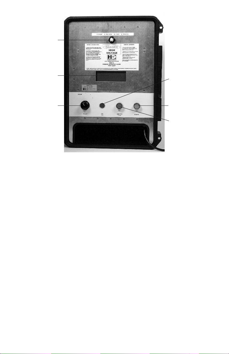
FACT-1 FRONT PANEL DESCR PT ON
1. TEST CABLE CONNECTOR - 3 binding posts for making connections to the individual
phases of the feeder. Each post is labeled to correspond to a particular phase of the feeder.
2. LCD DISPLA - The Liquid Crystal Display (LCD) for displaying instructions, messages,
and ammeter current.
3. SELECTOR KNOB - This rotary switch selects which phase is being tested at any
given time. When the knob is in the STANDBY position, no phase is selected.
4. SELF-TEST - Pressing this button initiates the Feeder All Clear Test Set the self-test
mode to assure proper operation. The test cable assembly must be removed during
the self test.
5. POWER - This button is the master power switch for the Feeder Ammeter Clear Test
Set. t is a latching pushbutton type. Pressing this button powers up all the electronics
and fan for operation
6. AMMETER CLEAR - Pressing this button provides 120V AC to the selected binding
post (Phase). t is a momentary pushbutton type. The button should not be pressed for
long periods of time since substantial heat can develop in the unit when there is a
ground on the feeder.
7. POWER CORD - Power cord for the unit. Cord must only plug into a 120V AC, 60Hz,
non-GFC 15 ampere outlet.
1
2
3 5
4
6

5
US NG THE FACT-1
CAUTION: Steps 1 through 6 should he performed with the feeder "grounded".
1. Make sure test cable assembly is NOT connected to the FACT-1.
2. Plug the FACT-1into a 120V, 60Hz, 3-prong outlet. The outlet should be rated for
a minimum of 15 Amps. Press the Red POWER switch to turn on the unit. The
POWER switch should illuminate and the fan located in the cord cavity should start.
IMPORTANT: The FACT-1 is not designed to work with any type of GFC protection device.
n a situation where a ground is left connected to the feeder, the FACT-1 will output current
on the corresponding phase however, the return current will be on the neutral/sheath of
the feeder and/or earth ground. Therefore the GFC device will detect the large differential
in current and open the circuit, prohibiting the unit from operating.
3. Perform a "Self-Test" of the unit prior to normal operation (see "Diagnostics").
IMPORTANT: The test cable assembly should NOT be connected to the FACT-1
during the Self-Test or the results may be incorrect and the test leads will become
energized with 120V.
4. Turn off the power to the unit by pressing the POWER switch again. The POWER switch
should no longer be illuminated and the fan will stop.
CAUTION: Assure that the feeder cable being connected to the FACT-1 is not energized.
The Feeder Ammeter Clear Test Set is not designed to be used or connected in the presence
of voltages greater than 300V.
5. Connect the test cable assembly to the FACT-1. Connect the appropriate test leads to
the A, B and C phase of the cables under test. Connect the ground lead to the neutral.
6. Turn the power on to the unit by pressing the POWER button.
NOTE: f for some reason the 3rd prong safety ground is not connected properly, a
message will be displayed on the LCD to repair the 3rd prong ground before operating.
CAUTION: The Feeder grounds need to be removed at this point. Assure there is no back
feed condition or voltage being applied to the feeder prior to the removal of the grounds.
IMPORTANT: The FACT-1 has been designed to also operate in situations where the polarity
of the 120 VA C outlet is "reversed". When the polarity is reversed, the output post that
becomes "live" when the AMMETER CLEAR button is pressed is also reversed. This will
be indicated on the LCD so that the operator does not have to remember; he simply
rotates the selector knob until the phase he wishes to test is indicated on the display.
The table below describes the internal logic:

6
120V Source Rotary Switch Phase to Ground Test Phase to Phase Test
Polarity Position (Output Phase) (Output Phase/Return Phase)
Correct Standby OFF OFF
Correct A PHASE A PHASE A to PHASE B
Correct B PHASE B PHASE B to PHASE C
Correct C PHASE C PHASE C to PHASE A
Reversed Standby OFF OFF
Reversed A PHASE B PHASE B to PHASE A
Reversed B PHASE C PHASE C to PHASE B
Reversed C PHASE A PHASE A to PHASE C
7. After the unit initializes, rotate the Selector Knob to Position A. The LCD will indicate
which phase the 120V AC voltage will be applied to.
8. Press and hold the AMMETER CLEAR button for several seconds. f there is any significant
current flow, the digital ammeter will display the current flow in 0.25Amp increments. f
there are no grounds connected to the phase either on the primary or secondary of a
transformer, and the phase indicated is not shorted to another, then the "NO FAULT"
message will be displayed:
A-ALIVE
NO FAULT DETECTED
Depending on the number of transformers connected to the network feeder during the
test, some small current (<0.3Amp) could be detectable due to the excitation currents of
the transformers. f the FACT-1 detects maximum current flow in the "live" (selected)
phase only, a phase to ground fault exists and is displayed:
A-ALIVE
PHASE A TO GND FAULT
f the FACT-1 detects maximum equal current in the output phase and the return phase,
then a phase-to-phase fault exists and is displayed:
B-ALIVE
PHASE B TO C FAULT
f the FACT-1 is operating with the transformer primaries connected to a feeder and a
ground is present on the secondary, the FACT-1 will detect its presence and display only
a partial reading. The actual reading obtained for a secondary fault will be dependent on
the windings of the transformer (turns-ratio) and the size (gauge) of the grounding
conductor. The heavier the grounding wire, the higher the current will be for secondary
faults. When secondary faults exist, they will be displayed as a phase-to-phase fault.
B-ALIVE
PHASE B TO C FAULT

7
9. After the selected phase has been tested and the AMMETER CLEAR button is released,
rotate the select knob to another position to test the other phases and repeat step 7
for each phase. The LCD will always indicate which phase that is being tested.
THERMAL OVERLOAD
The FACT-1 contains several resistors to limit the current supplied to the selected phase.
Since these resistors are required to dissipate several hundred watts, significant heat can
build up inside the case if the AMMETER CLEAR button is pressed for a long time on a
faulted cable. f the internal sensor detects a temperature that is too high, a message will
be displayed to the LCD:
Unit Temperature is Too High. Please Allow to Cool (with power switch on)
f this situation occurs, leave the FACT-1 plugged in with the POWER switch ON. This will
operate the fan and reduce the internal temperature. When the unit temperature' drops to
an operational level, the message will disappear and the unit may be used for testing again.
REVERSED POLARIT OPERATION
The FACT-1 has been designed to not only protect against an incorrectly wired outlet, but
to operate normally if such a situation arises. f the unit detects incorrect polarity, a message
is displayed to the operator to alert him of the situation. The operator must then press the
SELF-TEST button momentarily to clear the notice:
NOTICE: L NE CORD POLAR TY S REVERSED PRESS SELF-TEST TO CONT NUE
DIAGNOSTICS
The FACT-1 has built-in comprehensive diagnostics to assure that the FACT-1 is operating
correctly. The test cable assembly should NOT be connected to the FACT-1 during the Self-
Test. The Self Test mode is entered by pressing the SELF-TEST button. f at any time, you wish
to exit the Self-Test mode, simply press the SELF-TEST button a second time. The FACT-1 will
guide the operator through the Self-Test procedure using messages on the LCD.
Once Self-Test mode is entered, a message will be displayed to rotate the selector knob
to the correct position:
Rotate Switch to Pos A, then Press & Hold Ammeter Clear Button
(Self-Test to Cancel)
f the selector knob was already in that position or if the selector knob is rotated to that
position, the LCD will instruct the operator to press & hold the AMMETER CLEAR button
until a test PASS or test FA L message is displayed. Once the AMMETER CLEAR button
is released, the operator will be instructed to rotate the selector knob to each of the
remaining positions and to press the AMMETER CLEAR button.
At the conclusion of the test, an ALL TESTS PASSED or TEST FA LURE message will be
displayed before returning to normal operation.
The FACT-1 should never be operated outside of its maximum operating temperature
range of -20C to +60C (-4F to +140F). Operating the FACTS outside of its temperature
range may permanently damage the unit.

HD Electric Company is committed to ongoing review and improvement of its product lines,
and thus reserves the right to modify product design and specifications without notice.
HD Electric Company® products are available through HDE® sales representatives worldwide.
Printed in U.S.A. © HD Electric Company 2016 • Bulletin No. FACT M-200c
LIMITED WARRANT AND LIMITATION OF LIABILIT
This warranty applies to all products sold by HD Electric Company (the "Products"); provided, however, that the term Products does not include any
third party products purchased through HD Electric Company, for which no warranties are made (the "Third Party Products"). Third Party Products
may be subject to a separate manufacturer's warranty; [should you have any question regarding whether a separate warranty applies, please contact
HD Electric Company].
NOT CE: READ TH S L M TAT ON OF WARRANTY AND L AB L TY BEFORE BUY NG OR US NG THE PRODUCTS CONTA NED HERE N.
t is impossible to eliminate all risks associated with the use of the Products. Risks of serious injury or death, including risks associated with electrocution,
arcing and thermal burns, are inherent in work in and around energized electrical systems. Such risks arise from the wide variety of electrical systems
and equipment to which Products may be applied, the manner of use or application, weather and environmental conditions or other unknown factors,
all of which are beyond the control of HD Electric Company.
HD Electric Company does not agree to be an insurer of these risks, and shall have no liability for any claims arising from such risks.
WHEN YOU BUY OR USE THESE PRODUCTS, YOU AGREE TO ACCEPT THESE R SKS.
HD Electric Company warrants to the original purchaser that the Products (excluding any third party products purchased through HD Electric Company,
for which no warranties are made) will be free from defects in material and workmanship, under normal use and regular service, and preventative
maintenance for a period of one (1) year (ten (10) years for HDE Capacitor Controls) from the date of shipment (the “Warranty Period”). Should any failure
to conform with this warranty be found during the Warranty Period, you must notify HD Electric Company of your claim within thirty (30) days of discovery,
and within the Warranty Period. Your failure to give notice of claims of breach of warranty within the Warranty Period shall be deemed an absolute and
unconditional waiver of claims for such defects. HD Electric Company will have no responsibility to honor claims received after the date the applicable
Warranty Period expires.
Upon notice of your claim, HD Electric Company will provide a return authorization number, and further instructions on how to return the product for
service. You must follow HD Electric Company’s instruction. You are responsible for all Product removal, handling, re-installation, and shipping (both
to and from HD Electric Company). Products returned for repair, as well as repaired or replacement Products shall be sent postage / freight prepaid. After
receipt of a product which HD Electric Company determines is defective, HD Electric will, at its option, either (1) repair (or authorize the repair of) the
Product or (2) replace the Product, subject to the following: The Products are made using parts sourced from a variety of manufacturers. Due to the rapidly
changing technology environment, parts may become obsolete / unavailable over time (end of life). n the event that a Product cannot be repaired or
replaced due to unavailability of parts, HD Electric Company will use commercially reasonable efforts to obtain substitute parts or conduct work around
design, but cannot guarantee its ability to do so.
tems not found defective will be returned at your expense, or failing receipt of instruction from you on return of such items within five (5) business days
of our notice to you that the product is not defective, HD Electric may dispose of the product at its discretion and with no liability to you. HD Electric
Company’s determination of defects is final. Products repaired or replaced during the Warranty Period shall be covered by the foregoing warranties for
the remainder of the original Warranty Period or ninety (90) days from the date of delivery of the repaired or replaced Products, whichever is longer.
LIMITATIONS:
This warranty is void in the event of misuse, alteration, faulty installation, or misapplication of the product.
This warranty does not cover failure of product or components due to any ACT OF NATURE; lightning, floods, hurricanes, tornadoes or any other such
catastrophic events.
HD Electric Company does not warrant any third party products or associated hardware or their performance or suitability for use and application. Such
items are provided “as-is”.
All repairs must be authorized by HD Electric Company. Unauthorized repairs will not be reimbursed under any circumstances.
HD Electric Company is not required to make replacement or loaner equipment available while Products are being repaired or replaced, or to compensate
you for any in/out labor charges or expenses associated with removal, handling or re-installation of the Products.
TO THE MAX MUM EXTENT PERM TTED BY LAW, TH S WARRANTY AND THE REMED ES SET FORTH ABOVE ARE EXCLUS VE AND N L EU OF ALL OTHER
WARRANT ES, REMED ES AND COND T ONS, WHETHER ORAL OR WR TTEN, EXPRESS OR MPL ED. HD ELECTR C EXPRESSLY D SCLA MS ALL OTHER
WARRANT ES OF ANY K ND, EXPRESS OR MPL ED, NCLUD NG W THOUT L M TAT ON MPL ED WARRANT ES OF F TNESS FOR A PART CULAR PURPOSE,
MERCHANTAB L TY AND NON- NFR NGEMENT.
N NO EVENT SHALL HD ELECTR C COMPANY BE L ABLE FOR ANY ND RECT, NC DENTAL, CONSEQUENT AL OR SPEC AL DAMAGES RESULT NG FROM THE
USE OR HANDL NG OF THESE PRODUCTS. TH S SHALL NCLUDE BUT, NOT L M TED TO, LOST PROF TS OR REVENUE, LOSS OF USE OF THE PRODUCTS,
COST OF SUBST TUTE PRODUCTS, FAC L T ES OR SERV CES, OR DOWNT ME.
N NO EVENT SHALL HD ELECTR C COMPANY HAVE ANY L AB L TY FOR ANY TH RD PARTY PRODUCTS OR ASSOC ATED HARDWARE, OR
CUSTOMER-OWNED SYSTEMS, EQU PMENT OR SOFTWARE.
HD Electric Company must have prompt notice of any claim so that an immediate product inspection and investigation can be made. Buyer and all
users shall promptly notify HD Electric Company of any claims, whether based on contract, negligence, strict liability, or other tort or otherwise be barred
from any remedy.
Table of contents
Popular Test Equipment manuals by other brands


GW Instek
GW Instek GOS-6103C user manual

Project Fire
Project Fire Zonecheck Retrofit ZC450-R50 Instruction booklet

Agilent Technologies
Agilent Technologies N9360A Quick reference guide

Vega
Vega VEGAMET 381 Ex operating instructions

Klein Tools
Klein Tools VDV512-007 manual

Elcometer
Elcometer 139 user guide