Dantel 05615 User manual

CAUTION
•Install or remove modules from the shelf only when the power is off.
If you install a module in the shelf with the power on, the internal
circuitry may suffer damage and the product warranty will be void.
•Remove and install circuit boards only in a static-safe environment
(use antistatic wrist straps, smocks, footwear, etc.).
•Keep circuit boards in their antistatic bags when they are not in use.
•Do not ship or store circuit boards near strong electrostatic, electromag-
netic, magnetic, or radioactive fields.
•For more complete information on electrostatic discharge safety
precautions, refer to BellcoreTM Technical Reference # TR-NWT-000870.
Copyright 1998 by Dantel, Inc. • Dantel is a registered trademark of Dantel, Inc. • ISO 9001 Registered
Printed in the U.S.A.
INSTALLATION & OPERATION MANUAL
05615-0198 <90-00048>
05615 UNIVERSAL
ALARM TEST SET
About this Practice:
This practice has been reissued to:
• Meet ISO 9001 requirements.
Issue date: January 1998
Reissued Practices: Updated and
new content can be identified by a
banner in the right margin.
UPDATED
Table of Contents
Ordering Information ........................................................................... 2
General Description.............................................................................. 2
Installation............................................................................................ 3
Operation ............................................................................................ 13
Application Information ..................................................................... 14
Technical Specifications ..................................................................... 18
Warranty ............................................................................................. 20
44210-XX
460 MODEM
46020-XX
MULTI-ALARM
PROCESSOR
46022-3X
MULTI-ALARM
COMBINER
46090-01
RS-232
CONNECTOR
44210-XX 46022-XX 46090-01
46020-XX
1 432
RESET
XMT DATA
RESET
L
I
N
E
M
O
N
TD
OFF
HOOK
RING
DTR
RD
CD
CHAN
ENB
ESD
ESD
C2
C1
ESD

PAGE 2 05615-0198 <90-00048>
NOTE: This section lists the different options available for this product. To order any of the avail-
able options, contact Dantel Inside Sales through our toll-free number, 1-800-432-6835.
OPTION NUMBER FEATURES
A15-05615-01 Universal Alarm Test Set
A15-05615-21 Universal Alarm Test Set w/ A17-49023-00 Cable Kit
A15-05615-42 Universal Alarm Test Set w/ A17-49023-00 Cable Kit and A22-46508-02 40 MAP Editor
ORDERING INFORMATION
The 05615 Universal Alarm Test Set is a four-slot portable
400-type equipment shelf for testing alarm collection and
reporting equipment. It can poll equipment using DCP, DCPF,
TABS, TBOS, and DCM protocols, and can report alarm data in
DCP, DCPF, TABS, TBOS, and Printer (ASCII) protocols.
Alarm polling and reporting can be done through RS-232, RS-
422, RS-485, or 202 tone modem interfaces.
Configuration downloading to the 46020 Multiple Alarm Proces-
sor (MAP) requires Dantel’s 46508 40 MAP Editor. The configu-
ration can be downloaded:
♦Directly from a computer.
♦Through a dial-up modem in the test set.
♦Through a digital network connection.
A battery backup on the MAP module retains the configuration
when the test set is unplugged.
The test set housing features a carrying handle and non-slip
feet. It uses 120 VAC power.
GENERAL DESCRIPTION

05615-0198 <90-00048> PAGE 3
INSTALLATION
Installing the 05615 Universal Alarm Test Set consists of:
♦Setting switches and straps.
♦Connecting cables to external equipment.
♦Configuring the MAP.
♦Connecting the terminal to the MAP craft/printer port.
NOTE: Before beginning, verify that the Test Set is equipped as
illustrated on the front cover of this manual.
1. Set the switches and straps.
1. Refer to Fig. 1 and Table A for the 44210 460 Modem module strap
and switch settings. Set the straps as shown in Fig. 1.
2. Refer to Figs. 2 and Table B for the 46020 Multiple Alarm Proces-
sor (MAP) module switch settings. To download the configuration
file to the MAP, set the printer port protocol for DCPF or Printer
Protocol.
3. Refer to Fig. 3 and Table C for the 46022-30 Multiple Alarm Com-
biner (MAC) module switch settings. Set all switches on S1 OFF
(card and channel addresses are both 1).
4. Refer to Fig. 4 and Table D for the 49008 Current Loop Interface
subassembly strap settings.
5. Refer to Fig. 5 and Table E for the 49013 202 Modem subassembly
switch and strap settings.
6. Refer to Fig. 6 and Table F for the 49029 RS-232 Current Loop
Interface subassembly switch and strap settings.
7. There are no switch or strap settings for the 46090 RS-232 Connec-
tor module.
8. Install all modules in the test set.
NOTE: Each test set includes detailed A18-05615-42 application
drawings. You can also order application drawings as
necessary. These drawings show all connections and card
locations.
CONTINUED . . .

PAGE 4 05615-0198 <90-00048>
FIG. 1 - SWITCH AND STRAP LOCATIONS, 44210
TABLE A - SWITCH SETTINGS, 44210 (UP = OFF, DOWN = ON)
DESCRIPTION
Automated Answering Mode ON
Not used
1200 Baud Data Rate
1 Stop Bit
8 Bit Word Length
No Parity
SWITCH SETTING
S1-1 UP; S1-8 DOWN
S1-2 UP
S1-3 DOWN
S1-4 DOWN
S1-5 DOWN
S1-6 DOWN; S1-7 UP
FIG. 2 - SWITCH LOCATIONS, 46020
INSTALLATION
ON OFF
RTS
ON
DTR
EXT
GND TERM
422 DTR
422 TXD
485 TXD
1 2 3 4 5 6 7 8
VIEW
ROTATED
90 DEGREES
1 2 3 4 5 6 7 8 1 2 3 4 5 6 7 8 1 2 3 4 5 6 7 8 1 2 3 4 5 6 7 8
SWITCH 1 SWITCH 2 SWITCH 3 SWITCH 4
UP = OFF
DOWN = ON
1 2 3 4 5 6 7 8
1 2 3 4 5 6 7 8
1 2 3 4 5 6 7 8
S5
S6
S7
1 2 3 4 5 6 7 8
SWITCH 5

05615-0198 <90-00048> PAGE 5
TABLE B - SWITCH SETTINGS, 46020 (UP = OFF, DOWN = ON)
INSTALLATION
MASTER (S1) AND PRINTER (S2) PORT ADDRESSES
(Address 1 = Default) S1 = ALL DOWN
S2 = ALL DOWN
NOTE: For extended or additional information, refer to 46020-40 practice.
MASTER (S3) AND PRINTER (S4) PORT DATA RATES
S3-1 S3-2 S3-3 S3-4
S4-1 S4-2 S4-3 S4-4
1200 DOWN DOWN DOWN UP
2400 DOWN UP DOWN UP
9600 (Default) DOWN UP UP UP
MASTER (S3) AND PRINTER (S4) PORT PARITY
S3-5 S3-6
S4-5 S4-6
None (DCP, DCPF, Printer) (Default) DOWN DOWN
Odd (TBOS, TABS) UP DOWN
MASTER (S3) AND PRINTER (S4) PORT STOP BITS
S3-7
S4-7
1 Bit (Default) DOWN
MASTER (S3) AND PRINTER (S4) PORT WORD LENGTH
S3-8
S4-8
8 Bits (Default) UP
DATA PORT CONNECTED TO 46022-30 MAC
S5-1
MAC Select UP
POWER-UP OPERATION
S5-2 S5-3 S5-4 through S5-8
Cold Boot (erases memory) DOWN UP NOT USED ALL UP
Normal UP UP NOT USED ALL UP
MASTER PORT PROTOCOL
S6-1 S6-2 S6-3 S6-4
DCP DOWN DOWN DOWN DOWN
TBOS UP DOWN DOWN DOWN
DCPF UP UP DOWN DOWN
TABS DOWN DOWN UP DOWN
PRINTER PORT PROTOCOL
S6-5 S6-6 S6-7 S6-8
DCP DOWN DOWN DOWN DOWN
TBOS UP DOWN DOWN DOWN
Printer (Default) DOWN UP DOWN DOWN
DCPF UP UP DOWN DOWN
TABS DOWN DOWN UP DOWN
SWITCH S7
S7-1 through S7-8
Not Used All UP

PAGE 6 05615-0198 <90-00048>
FIG. 3 - SWITCH LOCATIONS, 46022-30
TABLE C - SWITCH SETTINGS, 46022-30
113
1
4
J5
J4
SUBASSEMBLY
OR
CARD ADDRESS CHANNEL ADDRESS
S1
O
N
O
F
1 2 3 4 5
FIG. 4 - STRAP LOCATIONS, 49008
P5 P4
J
E
AD
C
TABLE D STRAP SETTINGS, 49008
DESCRIPTION
CARD ADDRESS
Address 1
PORT ADDRESS
Port Address 1
SWITCH SETTINGS
S1-1 OFF; S1-2 OFF
S1-3 through 5 all OFF
OPTION
Unterminated Input
Terminated Input *
RS-422 *
RS-485
STRAP
J Strap removed
J Strap installed
Install straps A & C
Install straps C & E
NOTES: * = default setting. Remove J Strap
when using RS-422.
INSTALLATION

05615-0198 <90-00048> PAGE 7
FIG. 5 - SWITCH AND STRAP LOCATIONS, 49013
TABLE E - SWITCH AND STRAP SETTINGS, 49013
OPTION
S2
Normal Operation
MASTER/SLAVE STRAPS
Non-operative
RCV PAD STRAPS
IN (default - receive input level can
be between 0 and -20 dBm.)
OUT (receive input level can be
between -20 and -40 dBm.)
XMT PAD STRAPS
IN (transmit output level adjustable
between -20 and -40 dBm.)
OUT (default -transmit output level
adjustable between -1 and
-20 dBm.)
POSITION
NOR MASTER/SLAVE STRAPS
Remove straps from subassembly.
RCV PAD STRAPS
Place jumpers parallel to connector
P5.
Place jumpers perpendicular to
connector P5.
XMT PAD STRAPS
Place jumpers parallel to connector
P5.
Place jumpers perpendicular to
connector P5.
INSTALLATION
P5
P4
NOR
REV S2
XMT
MAS
SLA
NO STRAP
IN (DEFAULT)
IN
OUT
XMT RCV
OUT
(DEFAULT)
RCV
MAS
SLA
NO STRAP
IC2
NOTE: Dashed lines indicate default.

PAGE 8 05615-0198 <90-00048>
FIG. 6 - SWITCH AND STRAP LOCATIONS, 49029
TABLE F - SWITCH AND STRAP SETTINGS, 49029
OPTION
Mode (-00)
CTS Handshaking
Use CTS Handshaking
No CTS Handshaking
DCD Handshaking
Use DCD Handshaking
No DCD Handshaking
Paralleling (not used)
SWITCH/STRAP
Switch to -00 position (left)
X1 - THRU
X1 - ON
X2 - THRU
X2 - ON
X3 - jumper pins 1 & 2
INSTALLATION
X2 X1
X3
DCD CTS
THRU
ON
123
P5
P4
S1
-00 -01

05615-0198 <90-00048> PAGE 9
2. Connect the test set to external equipment.
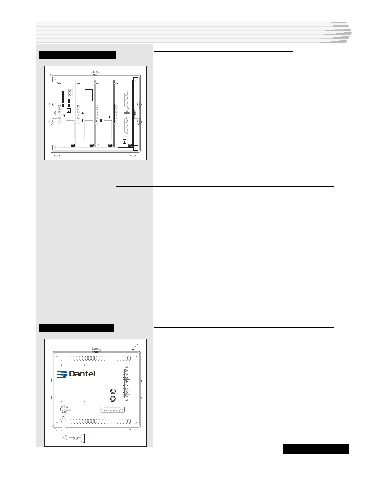
For the following steps refer to Figs. 7-9. Fig. 7 shows the test
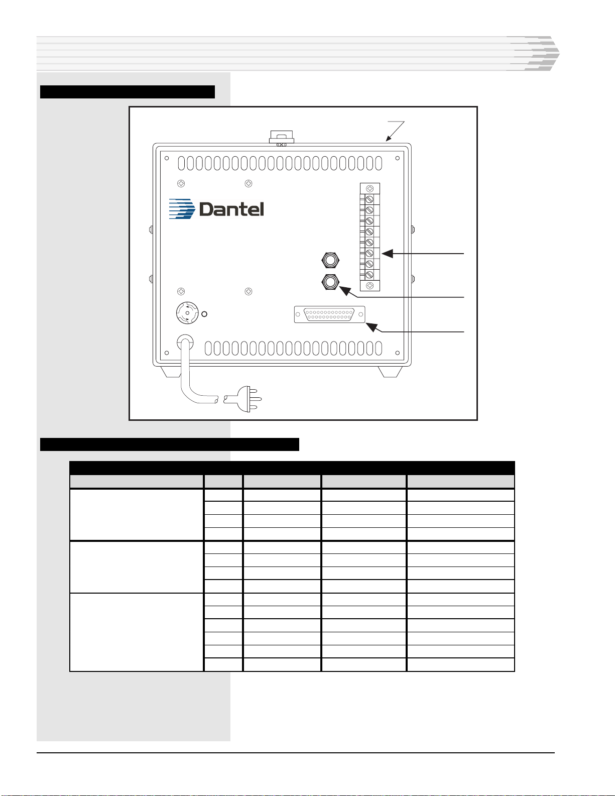
set front view. Fig. 8 shows the test set rear view. Fig. 10 shows
an interrogator/responder mode block diagram.
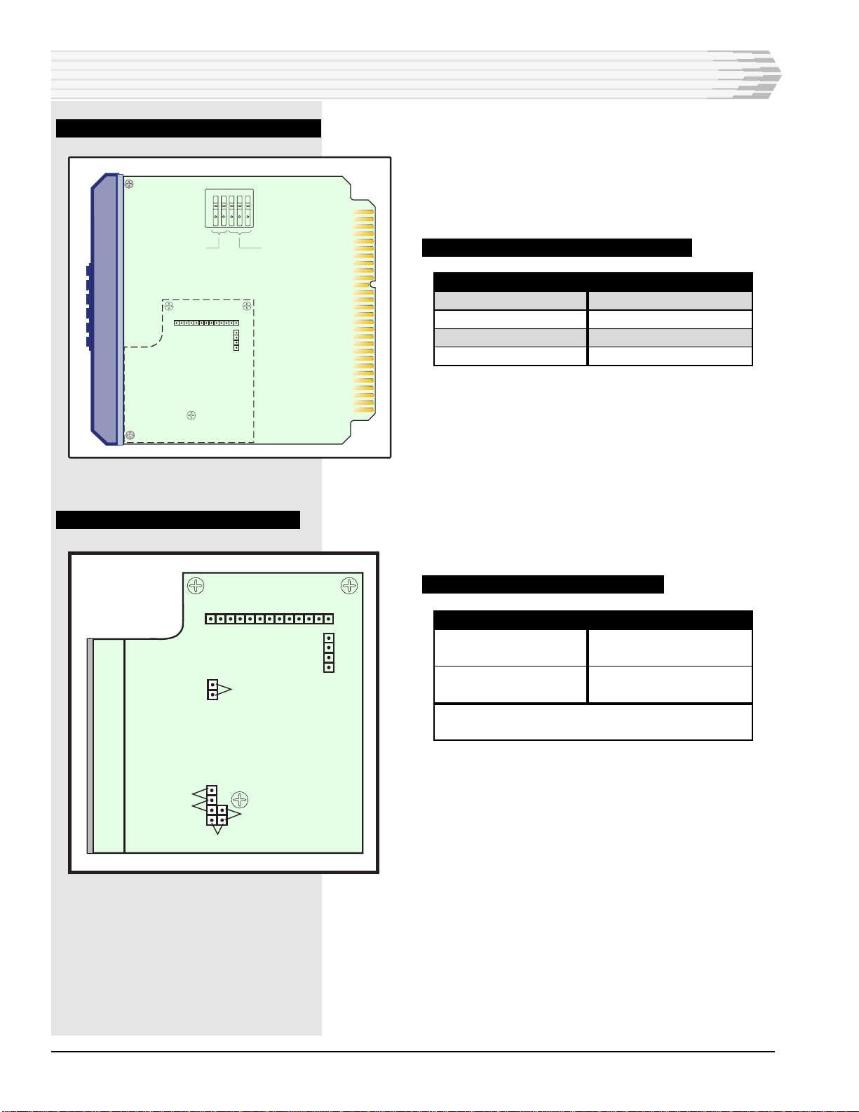
The MAP is the central module in the test set. Refer to Fig. 10.
The MAP has three ports – master, printer, and data – that
function as follows:
♦Master - Reports alarms to an alarm center.
♦Printer - Configuration port. It can also be used for local re-
porting of alarms because alarm information sent out the
printer port is a duplicate of the master port.
♦Data - Polls equipment for alarms.
Connect the master port to the alarm center. Use the top
DB25 connector on the 46090 module.
NOTE: Although the 46090 module says “RS-232” on the front panel, it
contains wiring only and will work with RS-422, RS-485, and
202 tone modem interfaces.
♦Connect the printer port to your computer so you can down-
load the configuration file to the MAP.
Refer to Fig. 10. To download the MAP remotely over a public
switched network, connect connectors 7 and 8 of TB-1 on the
back of the test set to tip and ring of a phone line. Or use the
bottom DB-25 connector on the 46090 module to connect the
printer port directly to your computer or to a digital network
connection.
Make sure the computer is set for the same baud, parity, and
stop bits as the MAP’s printer port.
NOTE: For a detailed explanation of the commands available to you
through the Printer Port, refer to the 46640 Firmware Manual.
♦The data port polls equipment for alarms through the
46022-30 MAC. Connect the MAC to alarm equipment at one
of three locations. See Figure 9 and Table G for pin designa-
tions.
FIG. 7 - FRONT VIEW
FIG. 8 - REAR VIEW
44210-XX
460 MODEM
46020-XX
MULTI-ALARM
PROCESSOR
46022-3X
MULTI-ALARM
COMBINER
46090-01
RS-232
CONNECTOR
44210-XX 46022-XX 46090-01
46020-XX
1 432
RESET
XMT DATA
RESET
L
I
N
E
M
O
N
TD
OFF
HOOK
RING
DTR
RD
CD
CHAN
ENB
ESD
ESD
C2
C1
ESD
F
U
S
E
F
U
S
E
F1
P
(
(
REAR PANEL
C1
J2
J1
TB-1
1
2
3
4
5
6
7
8
RX+
RX-
TX+
TX-
CONTINUED . . .
INSTALLATION

PAGE 10 05615-0198 <90-00048>
FIG. 9 - MAC CONNECTION POINTS
F
U
S
E
F
U
S
E
F1
P
(
(
REAR PANEL
C1
J2
J1
TB-1
1
2
3
4
5
6
7
8
RX+
RX-
TX+
TX-
Location #1
Location #2
Location #3
TABLE G - COMMUNICATION SUBASSEMBLY PIN DESIGNATIONS
MAC-30 E/W SUBASSEMBLY:
49008 (RS-422/485)
49013 (202 Tone)
49029 (RS-232)
TX+
TX-
RX+
RX-
TX+
TX-
RX+
RX-
RD
DTR
DCD
CTS
TD
RTS
LOCATION #1
(TB-1)
pin 4
pin 5
pin 1
pin 2
pin 4
pin 5
pin 1
pin 2
pin 1
pin 2
pin 3
pin 4
pin 5
pin 6
LOCATION #2
(310 JACKS)
J2-tip
J2-ring
J1-tip
J1-ring
J2-tip
J2-ring
J1-tip
J1-ring
J1-tip
J1-ring
n/a
J2-tip
J2-ring
n/a
LOCATION #3
C1 (BACK OF TEST SET
pin 5
pin 2
pin 3
pin 20
pin 5
pin 2
pin 3
pin 20
pin 3
pin 20
pin 8
pin 5
pin 2
pin 4
INSTALLATION

05615-0198 <90-00048> PAGE 11
3. Clear the memory in the MAP, if necessary.
Perform this step only if you are installing the MAP in the test
set for the first time or if you need to clear all memory.
1. Turn the test set off by flipping the rear panel power switch down.
Refer to Fig. 8.
2. Remove the 46020 MAP and place switch S5-2 DOWN.
3. Insert the MAP in the test set.
4. Turn the test set on by flipping the rear panel power switch up.
Refer to Fig. 8.
5. Wait ten seconds, then turn the test set off.
6. Remove the MAP and place switch S5-2 UP.
7. Insert the MAP in the test set.
4. Apply power to the test set.
Plug in the power cord and turn the test set on by flipping the
rear panel power switch up. Refer to Fig. 8.
5. Configure the MAP to operate.
Refer to the 46508 40 MAP Editor manual for instructions to
configure the MAP to operate.
6. Reconnect the printer port for alarm monitoring.
1. Flip the rear panel power switch off.
2. Set up the computer to operate as a terminal or remove the com-
puter and connect one of the following:
• A dumb terminal.
• A serial printer.
Change the switches on the MAP to set the printer port’s proto-
col for Printer (ASCII). Make sure the baud, parity, and stop bits
on the terminal or printer are the same as those for the printer
port of the MAP. Set S5-3, on the MAP, down. Insert the MAP in
the test set.
3. Flip the rear panel power switch on.
7. Align any modem subassemblies.
1. A modem must be connected to another modem at the other end of
the communications line.
2. Place the front panel switch in the TEST position.
3. Verify that the front panel CD (Carrier Detect) LED at the distant
end indicates data transmisssion activity.
4. With a dB meter (bridging), check the signal level at the XMT test
points. Adjust the XMT LVL to obtain the level required for your
application.
INSTALLATION
CONTINUED . . .

PAGE 12 05615-0198 <90-00048>
5. With a dB meter (bridging), check the incoming signal level at the
RCV test points. The signal level should be 0 to -40 dBm, depend-
ing on your application. There is no field adjustment for this circuit.
FIG. 10 - TEST SET
INSTALLATION
Serial
Printer
Dumb
Printer
F1
P
REAR PANEL
C1
J2
J1
TB-1
1
2
3
4
5
6
7
8
RX+
RX-
TX+
TX-
- DCM
- DCP
- DCP/F
- TBOS
- TABS
F
U
S
E
F
U
S
E
(
(
44210-XX
460 MODEM
46020-XX
MULTI-ALARM
PROCESSOR
46022-3X
MULTI-ALARM
COMBINER
46090-01
RS-232
CONNECTOR
44210-XX 46022-XX 46090-01
46020-XX
1 432
XMT DATA
L
I
N
E
M
O
N
TD
OFF
HOOK
RING
DTR
RD
CD
CHAN
ENB
MASTER
PRINTER
MASTER PORT
- DCP
- DCP/F
- TBOS
- TABS
PRINTER PORT
- DCP
- DCP/F
- TBOS
- TABS
- PRINTER
RESET
RESET
ESD
ESD
ESD
HOST
HOST
EQUIPMENT
UNDER TEST

05615-0198 <90-00048> PAGE 13
OPERATION
After you configure the test set it begins operation when you
plug the test set in and flip the rear panel power switch up.
The test set automatically interrogates equipment for alarms
based on the configuration in the MAP’s memory. The processed
alarms can be sent to the alarm center when requested or
monitored locally if a terminal or printer is connected to the
MAP’s printer port.
The MAP has a battery to retain the configuration when the test
set is unplugged or if power goes out. When power is restored,
the MAP resumes operation.
NOTE: You must configure the MAP with Dantel’s 40 MAP Editor
software (46508) to collect and process alarms correctly.
LEDs on the front panels of the modules and subassemblies
show the activity on the transmit and receive paths and the
handshaking lines.
There is a reset button on the front panel of the 44210 460
Modem module that you can push if you need to reinitialize the
modem.

PAGE 14 05615-0198 <90-00048>
APPLICATION INFORMATION
Connect the test set to other systems using the 05615 Univer-
sal Alarm Test Set Cables Package. Refer to Fig. 11. The
test set has multiple ports for communications with various
external alarm systems. Refer to Fig. 12. Use the types of cables
for connecting to different systems.
Fig. 13 shows a standalone alarm interrogator application. The
test set automatically interrogates alarms based on
preprogrammed instructions stored in non-volatile RAM
memory. The processed alarms route to the master computer
upon request. The MAP printer port has alarm information in
ASCII format.
Fig. 14 shows a TABS/TBOS responder application. The test set
connects to an alarm master system using TABS, TBOS or
another protocol through port C2 of the 46090 RS-232 Connec-
tor. Port C1 of the 46090 RS-232 Connector connects to a local
configuration or monitor port.
Use the 46022-3X Multiple Alarm Combiner for a four wire
connection to a local TABS or TBOS device being tested. You can
also use the 44210 460 Modem for a dial-up configuration.
Fig. 15 shows a TABS/TBOS interrogator application. The test
set connects to an alarm master system using DCP, DCPF or
another protocol through port C2 of the 46090 RS-232 Connec-
tor. All other connections are the same as the TABS/TBOS
responder application.
The test set automatically interrogates alarms based on
preprogrammed instructions stored in non-volatile RAM
memory. The processed alarms route to the master computer
upon request. The MAP printer port has alarm information in
ASCII format.

05615-0198 <90-00048> PAGE 15
FIG. 11 - UNIVERSAL ALARM TEST SET CABLE PACKAGE (A17-49023-00)
Red2
White3
Black4
Green20
3
2
7
8
6
5
1
9
4
Dantel Alarm Test Set: A18-05615-42
Various cables may be used to provide system connections depending on what customer
equipment is to be attached. See Block Diagram for pinouts
DB-25 Connector (Male) To Wire-wrap pins (Female)
4 conductors, multi-strand, shielded, with strain relief.
(P/N A25-00707-00)
DB-25 Connector (Male) To DB-9 Connector (Female)
Dantel P/N:999-00367-00
(Null Modem Cable)
"310" Connector (Male) To Wire-wrap pins (Female)
(P/N A25-00706-00)
ALARM EQUIPMENT INTERFACE
RS 422/RS 485
PC INTERFACE
RS 232
(P/N 929-00057-00)
RJ-11 plug to Spade Connectors
2
3
7
2
3
7
White
Black
Green
Red
"Spade Lug" Crimp Connector to
Wire-wrap pins (Female)
CP/N A25-00705-00
Yellow
Green
Red
Black
Yellow
Green
Red
Black
SIDE
VIEW
REAR
VIEW
ADAPTOR KIT
BLACK BOX P/N: 915-00068-00
DCE APPLICATION PIN OUT DTE APPLICATION PIN OUT
TYPICAL RJ-45 TO DB-25 KIT PIN OUTS (WIRED BY CUSTOMERS)
RJ-45S
R1
RTS
DCD/DSR
RD
CTS
SIG GND
DTR
TD
R1
RTS
DCD
DSR
RD
CTS
SIG GND
DTR
TD
1
2
3
4
5
6
7
8
22
4
8
6
3
5
7
20
2
MALE DB25 RJ-45S
R1
RTS
DCD/DSR
RD
CTS
SIG GND
DTR
TD
BUSY OUT
DCD
RTS
DTR
TD
PIN 11
SIG GND
DSR
RD
1
2
3
4
5
6
7
8
22
4
8
6
3
5
7
20
2
MALE DB25
Yellow
Green
Red
Black
2
3
4
5
6
7
8
22
20
DB-25 Connector (Male) To DB-25 Connector (Male
(Straight Ribbon Cable)
(P/N 929-00056-00)
ALARM EQUIPMENT INTERFACE
RS 232
APPLICATION INFORMATION

PAGE 16 05615-0198 <90-00048>
FIG. 12 - UNIVERSAL TEST SET CONNECTIONS
44210-XX
4
6
0
2
2
-3X
44210-XX
4
6
0
2
0
-40
44210-XX
4
4
2
1
0
From
equipment
being
monitored
To PC,
dumb terminal
or serial printer
Screw Terminal
DB-25 Connector
Female, (DCE)
Data Port Access
(Alarms In)
Printer Port Access
(Local Display/Config.)
DB-25 Connector
Female, (DTE)
DB-25 Connector
Female, (DTE)
Master Port Access
(Alarms Out)
To/From
Telephone jack
for remote
access
Dantel Universal Alarm Test Set: A18-05615-42
TEST SET CONNECTIONS:
The 5615 Test Set is equipped with multiple ports for communications with various external alarm systems.
The drawing below illustrates the input, output, and configuration connections.
To HOST
computer
Screw
Terminal
"310 Jack"
FIG. 13 - STANDALONE ALARM INTERROGATOR APPLICATION
46020-XX
4
6
0
2
0
-40
44210-XX
4
4
2
1
0
Dantel Universal Alarm Test Set: A18-05615-42
STANDALONE ALARM INTERROGATOR APPLICATION:
Test Set automatically Interrogates alarms based on pre-programmed instructions stored in
Non-Volatile RAM memory. The processed alarms are sent to the master computer when
requested. Alarm information is also available at the Printer port of the MAP in ASCII.
46022-XX
4
6
0
2
2
-30
46022-XX
4
6
0
9
0
Local Configuration/
Monitor Port:
Outputs ASCII Alarm
information to PC,
Terminal, or serial printer.
4-wire connection to
local TABS or TBOS
device under test.
(4K' maximum, RS-422
standard)
64 Alarm Displays or
4906 points.
Dial-Up
Configuration/Monitor
Modem (Optional)
APPLICATION INFORMATION

05615-0198 <90-00048> PAGE 17
FIG. 14 - TABS/TBOS RESPONDER APPLICATION
FIG. 15 - TABS/TBOS INTERROGATOR APPLICATION
APPLICATION INFORMATION
Dantel Universal Alarm Test Set: A18-05615-42
TABS/TBOS INTERROGATOR APPLICATION:
Test Set automatically Interrogates alarms based on pre-programmed instructions stored in
Non-Volatile RAM memory. The processed alarms are sent to the master computer when
requested. Alarm information is also available at the Printer port of the MAP in ASCII.
Local Configuration/
Monitor Port
DCP/DCPF (or other
protocol) output to
alarm master system.
(RS-232, RS-422/485,
202T Interfaces).
4-wire connection to
local TABS or TBOS
device under test.
(4K' maximum, RS-422
standard)
64 Alarm Displays or
4906 points.
Dial-Up
Configuration/Monitor
Modem (Optional)
46020-XX
4
6
0
2
2
-40
44210-XX
4
4
2
1
0
46022-XX
4
6
0
2
2
-30
46022-XX
4
6
0
9
0
REMOTE ACCESS OPTION
Local Configuration/
Monitor Port
Dantel Universal Alarm Test Set: A18-05615-42
TABS/TBOS RESPONDER APPLICATION:
DCP/DCPF (or other
protocol) output to
alarm master system.
(RS-232, RS-422/485,
202T Interfaces).
4-wire connection to
local TABS or TBOS
device under test.
(4K' maximum, RS-422
standard)
64 Alarm Displays or
4906 points.
Dial-Up
Configuration/Monitor
Modem
46020-XX
4
6
0
2
0
-40
44210-XX
4
4
2
1
0
46022-XX
4
6
0
2
2
-30
46022-XX
4
6
0
9
0
REMOTE ACCESS OPTION
Test Set simulates a TABS/TBOS Device when polled by an interrogator.

PAGE 18 05615-0198 <90-00048>
TECHNICAL SPECIFICATIONS
DESCRIPTION
Configuration
RS-232 Direct Connection
or
Dial-Up (212) Connection
Memory
Interface
Input Voltages
Weight
Physical Dimensions
Operating Temperature Range
DESCRIPTION
RS-232 Direct Connection
Dial-up (212) Connection
64 displays maximum (4096 alarm points)
RS-422/485 * * Depending on
RS-232 * subassemblies
202 Tone * used
117 VAC (0.5 Amps)
6.5 lbs.
7.0" x 7.0" x 10.0"
0° to 55° C.

05615-0198 <90-00048> PAGE 19
NOTES

PAGE 20
20 PAGES 05615-0198 <90-00048>
LIMITED WARRANTY
The Seller warrants that the standard hardware products sold will be free from defects in material and work-
manship and perform to the Seller’s applicable published specifications for a period of 18 months for hardware,
and 3 months for software, from the date of the original invoice. The liability of the Seller hereunder shall be
limited to replacing or repairing, at its option, any defective products which are returned F.O.B. to the Seller’s
plant, (or, at the Seller’s option, refunding the purchase price of such products). In no case are products to be
returned without first obtaining permission and a customer return authorization number from the Seller. In
no event shall the Seller be liable for any consequential or incidental damages.
Equipment or parts which have been subject to abuse, misuse, accident, alteration, neglect, unauthorized
repair or installation are not covered by warranty. The Seller shall make the final determination as to the
existence and cause of any alleged defect. No warranty is made with respect to custom equipment or products
produced to the Buyer’s specifications except as specifically stated in writing by the Seller in the contract for
such custom equipment.
This warranty is the only warranty made by the Seller with respect to the goods delivered hereunder, and may
be modified or amended only by a written instrument signed by a duly authorized officer of the Seller and
accepted by the Buyer.
Warranty and remedies on products not manufactured by the Seller are in accordance with warranty of the
respective manufacturer. THE SELLER MAKES NO OTHER WARRANTY OF ANY KIND WHATSOEVER,
EXPRESSED OR IMPLIED; AND ALL IMPLIED WARRANTY OF FITNESS FOR A PARTICULAR PUR-
POSE WHICH EXCEEDS THE AFORESAID OBLIGATIONS IS HEREBY DISCLAIMED BY THE SELLER.
INCASE OF DIFFICULTY
If you experience difficulty with this equipment, check the following, as appropriate:
1. Switch settings
2. Signal levels
3. Software configuration
4. Connections between Dantel’s equipment and your equipment.
If there is still a problem, substitute equipment that is known to be good. For additional assistance, call
Dantel’s Technical Field Service Department weekdays, 6 A.M. to 5 P.M. pacific time:
1-800-4DANTEL(1-800-432-6835).
If a thorough checkout shows a piece of equipment has malfunctioned, you may return it to the factory. For
repairs and emergency replacements, obtain a Return Material Authorization (RMA) number from the Cus-
tomer Service Representative at 1-800-4DANTEL (1-800-432-6835).
To ensure expedient processing of your order, provide a purchase order number and shipping and billing
information when requesting an RMA number. Also, when the units are returned to Dantel, include a descrip-
tion of the failure symptoms for each unit returned. Send defective equipment to:
Dantel, Inc. • 2991 North Argyle Avenue • Fresno, California 93727-1388
P.O. Box 55013 • Fresno, CA 93747-5013 Phone (209) 292-1111 Fax (209) 292-9355 http://www.dantel.com
WARRANTY
This manual suits for next models
3
Table of contents