BEAMEX CENTRICAL User manual
USER MANUAL - BEAMEX CENTRICAL AND
SUPPORTING MODULES
Dear user,
We have made every effort to ensure the accuracy of the contents of this manual.
Should any errors be detected, we would greatly appreciate to receive sugges-
tions to improve the quality of the contents of this manual.
For more detailed technical data about Beamex CENTRiCAL, please contact the
manufacturer.
8888200 / CENTRiCALuEng / Version 1
© Beamex 2019
BEAMEX OY AB
Ristisuonraitti 10
FIN-68600 Pietarsaari
FINLAND
Tel +358 - 10 –5505000
Fax +358 - 10 –5505404
E-mail: [email protected]m
service@beamex.com
Internet: http://www.beamex.com


User Manual - Beamex®CENTRiCAL and Supporting Modules - Contents i
CONTENTS
Part 1, Introduction
General 2
About This Manual..................................................................2
Where Am I?....................................................................3
Typographical Conventions .............................................3
Unpacking and Inspection ......................................................4
Part 2, CENTRiCAL
CENTRiCAL 6
General ..................................................................................6
CENTRiCAL M and F models.................................................7
Corner Unit, models CM and CF.............................................7
Dimensions.............................................................................8
Connecting the CENTRiCAL to the Electrical Network .........10
Pressure Supply Connections...............................................11
Electrical Connections..........................................................12
Part 3, CENTRiCAL Trolley
About CENTRiCAL Trolley 14
CENTRiCAL Trolley's Contents............................................15
Connecting the CENTRiCAL to the Electrical Network .........15
Pressure Supply Connections...............................................16
Electrical Connections..........................................................16
Part 4, Pressure Measurement Modules
General 18
Available Pressure Measurement Module Types and
Their Measurement Ranges................................................. 19
Installing and Uninstalling Pressure Measurement
Modules............................................................................... 20
Removing a Pressure Measurement Module................. 20
Adding a Pressure Measurement Module...................... 21
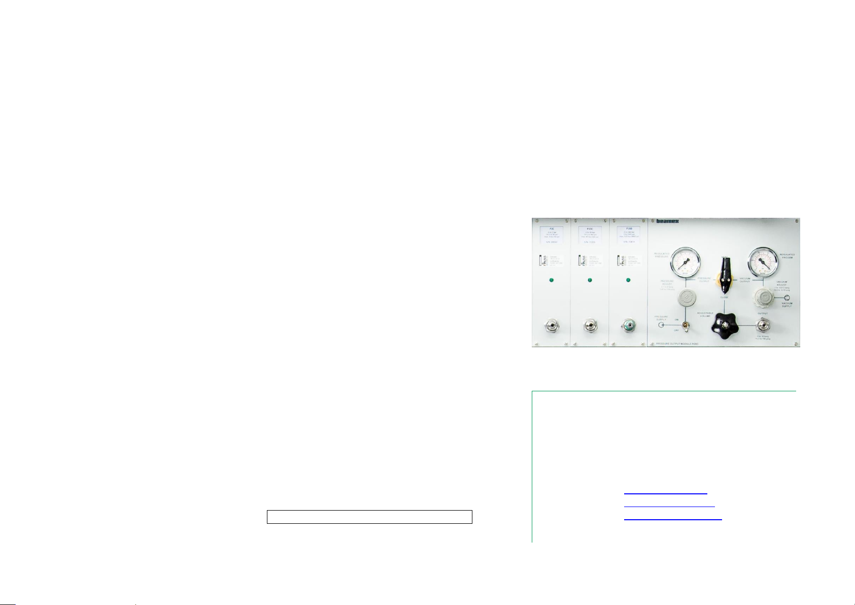
Part 5, Pressure Output Modules
General 24
Diagrams of Pressure Output Modules ................................ 25
PO8C 26
Connections......................................................................... 27
Specifications....................................................................... 28
General......................................................................... 28
Pressure Adjuster.......................................................... 28
Vacuum Adjuster........................................................... 29
Adjustable Volume........................................................ 29
Output Connector.......................................................... 29
Service................................................................................. 30
Selector Valve............................................................... 30
Operation............................................................................. 31
PO20 32
Operation............................................................................. 33
Connections......................................................................... 34
PO210 35
Preparation.......................................................................... 36
Operation............................................................................. 36
Connections......................................................................... 37
Maintenance of the Pressure Output Modules 38

ii User Manual - Beamex®CENTRiCAL and Supporting Modules - Contents
Appendix
Pressure Connections 36
Safety 38
Symbols Used...................................................................... 38
Environmental Specifications ...............................................38
Standard, Desktop, Heavy Duty & Low
Workstations .................................................................38
Safety Precautions and Warnings........................................ 39
General Warnings......................................................... 40
General Warnings Concerning Pressure
Measurement................................................................ 41
Warnings Concerning High Pressure ............................42
Disposal of Waste Electrical and Electronic Equipment 43
Beamex and WEEE ............................................................. 43
Service 44
General................................................................................ 44
Statements 45
Disclaimer............................................................................45
EU........................................................................................45
Intellectual Property Rights ..................................................46
Copyright....................................................................... 46
Trademarks................................................................... 46
Index 39

User Manual - Beamex®CENTRiCAL and Supporting Modules - Feedback iii
FEEDBACK
We want to improve our products and services constantly. Therefore we’d like to
know Your opinion of the product You use. Please spend a moment of Your val-
uable time in filling this form. All respondents will receive a surprise gift in return.
Certain questions can be answered immediately after receiving the product. Oth-
ers require some use of the product before You are able to answer them. The
best way to fill the form is to answer the items as it applies, and send the form to
us when all items are answered. There are however no definite restrictions; fill in
the form when you feel like it (all items need not be answered). Then send it to
Beamex using one of the possibilities listed to the right.
Mail: Beamex Oy Ab
Quality Feedback
Ristisuonraitti 10
FIN-68600 Pietarsaari
FINLAND
Fax: +358 - 10 - 5505404
Only the next page needs to be
faxed to us.
Internet: http://www.beamex.com
A similar form is available as a web page
E-mail: [email protected]
Refer to the numbered items on the next
page in Your e-mail message.
iv User Manual - Beamex®MCS200 Calibration Workstation, Supporting Modules - Feedback
1. Name of the product you give feedback of:
_____________
2. Serial number and software version number
_____________ / _____________ (if applicable)
3. Any comments when receiving the product. Did the package con-
tain all required items and was it as expected?
____________________________________________
____________________________________________
____________________________________________
4. For how long have you been using the product?
_____________
5. How helpful was the manual in using the product?
(Tick a box in the percentage scale below)
6. How well did the product suit your needs?
7. How satisfied are you with the product?
8. Did anything in the product exceed your expectations? In that
case, what was it?
____________________________________________
____________________________________________
____________________________________________
9. Did anything in the product disappoint you? In that case, please
specify.
____________________________________________
____________________________________________
____________________________________________
10. Any ideas You want to propose to Beamex so that we can im-
prove our products, operations and/or services.
____________________________________________
____________________________________________
____________________________________________
Please fill in these fields in order to receive your surprise gift.
Title & Name: ______________________________________
Address: ______________________________________
_________________________________________________
_________________________________________________
Please contact me concerning the Feedback I have given.
I want to receive more information on Beamex products.
Size (tick one)
XS S M L XL XXL

Things discussed in this part:
About this manual.
Unpacking CENTRiCAL.
Part 1
INTRODUCTION

2 User Manual - Beamex CENTRiCAL and Supporting Modules –Part 1, Introduction
GENERAL
This manual presents information of Beamex®CENTRiCAL's Supporting Mod-
ules. The modules in the CENTRiCAL can be grouped into four main types:
1. Host modules (Calibrator modules):
MC6 Workstation calibration host module
2. Supporting modules, divided into:
P’s, i.e. Pressure Measurement Modules,
PO’s, i.e. Manual Pressure Output Modules,
3. HERA and third party modules
4. POC8 Automatic Pressure Controller module
Using MC6 Workstation calibration host module, POC8 Automatic Pressure
Controller, Power Supplies, Measuring instruments and other modules are cov-
ered in separate manuals.
Attention!
Before taking CENTRiCAL and its Modules into use, please
read the warnings available in Part A, Appendix.
ABOUT THIS MANUAL
CENTRiCAL User Manual for Supporting Modules is divided into several parts as follows:
Part 1, Introduction discusses general matters.
Part 2, CENTRiCAL discusses CENTRiCAL related matters
Part 3, CENTRiCAL Trolley discusses movable Calibration System re-
lated matters
Part 4, Pressure Measurement Modules discusses Pressure Measure-
ment Modules used in conjunction with MC6 Workstation.
Part 5, Pressure Output Modules are tools for
creating exact pressures for calibration needs.
Part A, Appendix discusses pressure connec-
tions, safety, warnings etc.

General - About This Manual 3
WHERE AM I?
The header of each spread in CENTRiCAL User Manual informs you of where
you are: The even page shows the part you are in and the odd page shows the
main topic you are currently viewing.
Example of even page header:
2 CENTRiCAL User Manual –Part 1, Introduction
Example of odd page header:
General - About This Manual 3
TYPOGRAPHICAL CONVENTIONS
The following typographical conventions apply to CENTRiCAL User Manual:
Bold text is used in following situations:
References to User Manual topics and parts and
Keywords, i.e. terms shown in the related to CENTRiCAL or its modules.
Notes are shown in Narrow text with a border above and to the
left of the note text. Notes typically inform you of something use-
ful concerning the current topic.
Warnings are shown in Narrow and Bold. They also have a
shaded background and are surrounded by a border line.
Whenever you see a warning, read it carefully and take it
seriously. By not observing warnings, you may - at
worst - damage the calibrator and/or even risk your life.

4 User Manual - Beamex CENTRiCAL and Supporting Modules –Part 1, Introduction
UNPACKING AND INSPECTION
At the factory each new CENTRiCAL module passes a careful inspection. It
should be free of scrapes and scratches and in proper operation condition upon
receipt. The receiver should, however, inspect the unit for any damage that may
have occurred during transit. If there are signs of obvious mechanical damage,
package contents are incomplete, or the module does not operate according to
specifications, contact the purchasing sales office as soon as possible.
All the modules purchased with CENTRiCAL are pre-installed in the Instrument
Panel at the factory except POC8 which is packed in a cardboard box and
needs to be installed on a POC8 Holder by the customer. Pressure Module in-
stallation specifics can be found is this manual's Part 4, Pressure Measure-
ment Modules.
If you have to return a module or another part of the CENTRiCAL to the factory
for any reason, include a detailed description of the reason for the return. Read
also chapter Service in Part A, Appendix.
Standard accessories:
Accredited calibration certificate, for modules
requiring one,
this User Manual,
Warranty Card,
depending on the included modules:
pressure hoses, test leads and/or clips.

Things discussed in this part:
A presentation of CENTRiCAL Calibration Systems
Part 2
CENTRICAL
6 User Manual - Beamex®CENTRiCAL and Supporting Modules –Part 2, CENTRiCAL
CENTRICAL
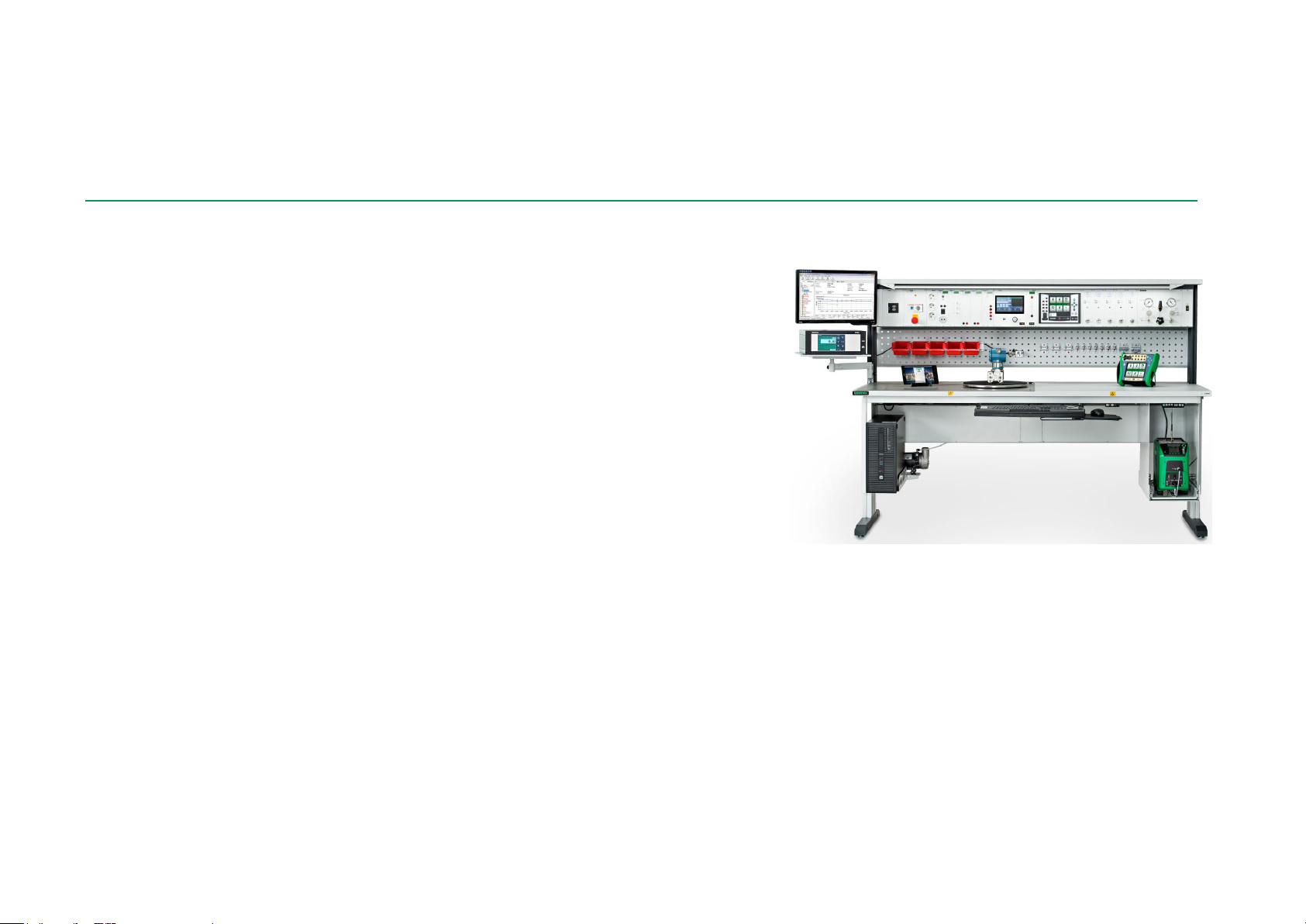
GENERAL
The CENTRiCAL is a Modular Calibration System for calibration and mainte-
nance of process instruments, like transmitters, converters, temperature
probes, recorders, indicators, etc. The system is designed for instrument/electri-
cal workshops and laboratories.
The modular construction of the system allows the user to customize the CEN-
TRiCAL to practically any measurement and calibration application.
The modules in the CENTRiCAL can be grouped into four main types:
1. Host modules (Calibrator modules):
MC6 Workstation Calibration Host Module.
2. Supporting modules, divided into:
P’s, i.e. Pressure Measurement Modules,
PO’s, i.e. Manual Pressure Output Modules and
3. HERA and third party modules
4. POC8 Automatic Pressure Controller module

CENTRiCAL - CENTRiCAL M and F models 7
CENTRICAL MAND FMODELS
CENTRiCAL Calibration System is available as following models:
CENTRiCAL M, motor operated height adjustment for table top and In-
strument Panel
CENTRiCAl F, fixed 78 cm high table top and Instrument Panel
Each version consists of
a table frame,
a table top
a Function Board
an Equipment Panel and
an Instrument Panel
All the modules purchased with the CENTRiCAL are pre-installed in the Instru-
ment Panel at the factory except POC8 which is packed in a cardboard box and
needs to be installed on a POC8 Holder by the customer.
CORNER UNIT,MODELS CM AND CF
Corner unit is available as following models:
Corner CM, motor operated height adjustment for table top and Instru-
ment Panel
Corner CF, fixed 78 cm high table top and Instrument Panel
With a Corner Unit you are able to group two separate CENTRiCAL M or F Mod-
els together to form a larger entity.
Please notice!
When you use a corner CM to group two CENTRiCAL M Mod-
els, you have to plug together the lifting controllers of the tables
before you connect CENTRiCAL to the Electrical Network. Oth-
erwise the lift will lose its programming.
8 User Manual - Beamex®CENTRiCAL and Supporting Modules –Part 2, CENTRiCAL
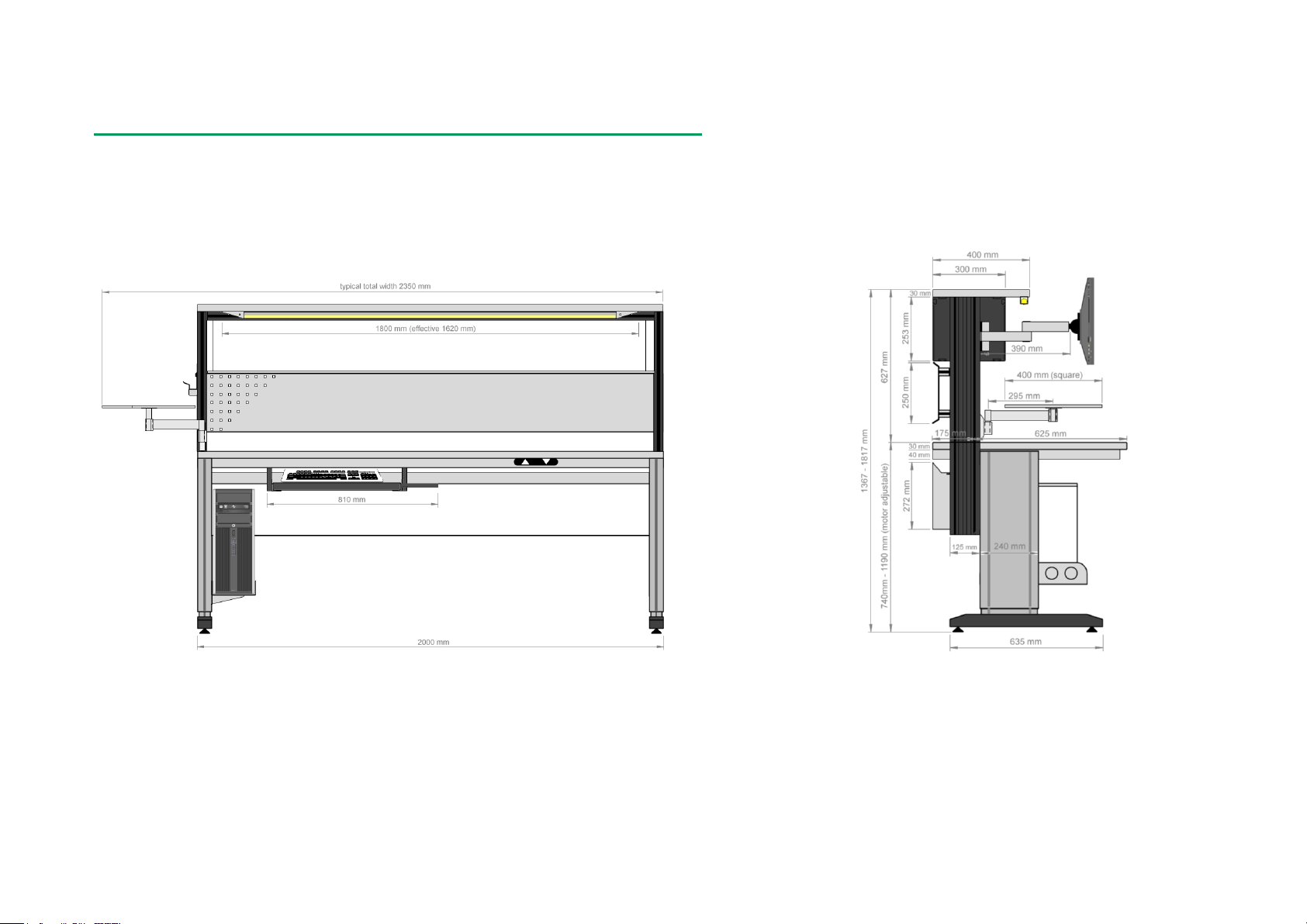
DIMENSIONS
The dimensions for the CENTRiCAL M and F models are the same:
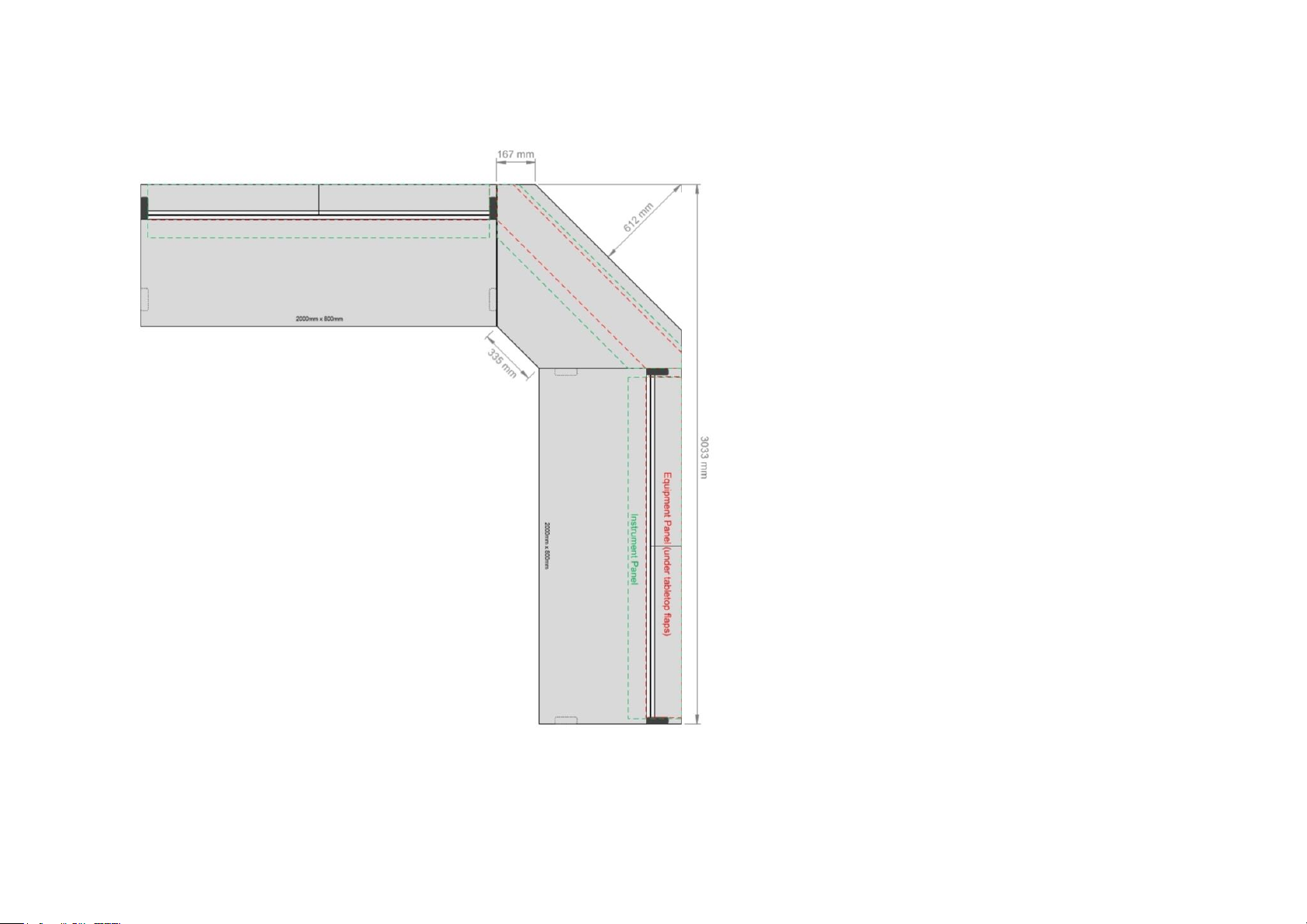
CENTRiCAL - Dimensions 9
The dimensions for the Corner CM and CF models are also the same:

10 User Manual - Beamex®CENTRiCAL and Supporting Modules –Part 2, CENTRiCAL
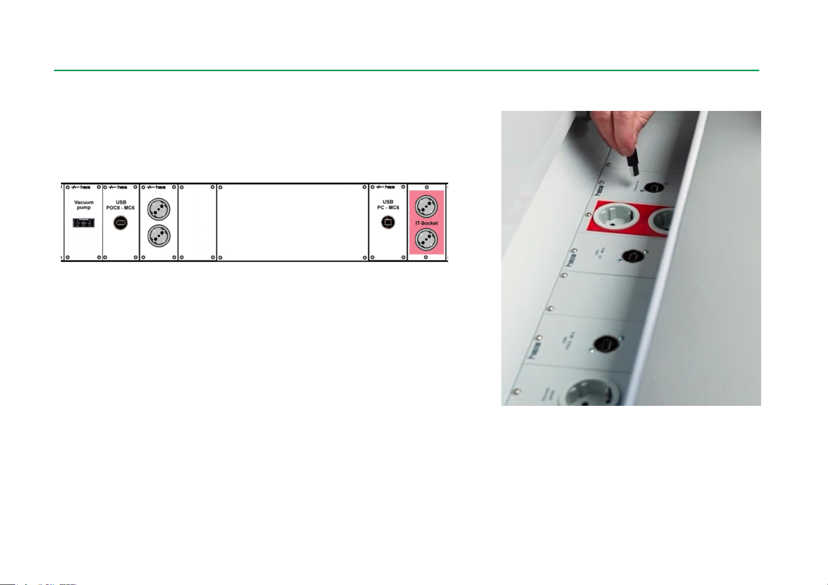
CONNECTING THE CENTRICAL TO THE ELECTRICAL NETWORK
CENTRiCAL is equipped with two power cords. One of them is an IT-socket
(marked) and meant for powering computers. It is always powered even if the
power is turned off from the Instrument Panel. To turn it off, just disconnect the
power cord from the wall socket. The other cord is the mains cable (marked)
and meant for powering the modules in the Instrument Panel and Function
Board.
To connect the CENTRiCAL to the electrical network do the following:
1. Be sure that all the ON-OFF -switches in the module rack are switched
OFF.
2. Connect the mains cables to an earthed AC outlet (wall socket).
3. Turn the main switch of the workstation ON (remember to check that the
automatic fuses are in position I).
4. If any problems appear during the startup, please contact the manufac-
turer or your local distributors.
Warning!
Before connecting the CENTRiCAL to the mains, check that
the mains voltage is as marked on the rear panel of the CEN-
TRiCAL
CENTRiCAL - Pressure Supply Connections 11
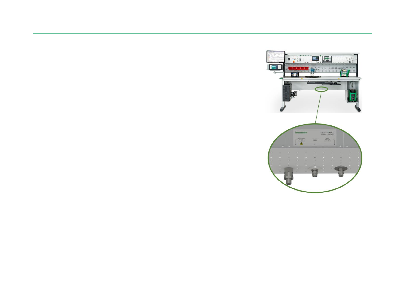
PRESSURE SUPPLY CONNECTIONS
The pressure supply connections are located in the middle of the Function
board under the table top (marked with a sticker). Pressure supply is required
for Pressure Output Modules.
Vacuum pump (if ordered) is pre-installed and connected at the factory to vac-
uum supply.
CENTRiCAL requires clean, dry and oil free instrument air supply. Filtering of
the instrument air supply is included in the base unit. The filter may be located
according to user’s needs, but it needs to be part of the instrument air supply
system at all times.
High pressure supply is needed for PO20 and PO210.
Instrument air and high-pressure supply hoses need to be connected to the cor-
responding connectors. Suitable hoses can be found from the CENTRiCAL
Customer Connections Kit.
12 User Manual - Beamex®CENTRiCAL and Supporting Modules –Part 2, CENTRiCAL
ELECTRICAL CONNECTIONS
Electrical connections are located either in Instrument Panel or Equipment
Panel.
Equipment Panel is located in the Function Board at the back of the table top
under flaps. There are e.g connectors for MC6 - POC8 communication and
computer interface for MC6WS.

Things discussed in this part:
A presentation of CENTRiCAL Trolley movable Cali-
bration System
Part 3
CENTRICAL TROLLEY

14 User Manual - Beamex®CENTRiCAL and Supporting Modules –Part 3, CENTRiCAL Trolley
ABOUT CENTRICAL TROLLEY
The CENTRiCAL Trolley is a movable Modular Calibration System for calibra-
tion and maintenance of process instruments, like transmitters, converters, tem-
perature probes, recorders, indicators, etc. The system is designed for instru-
ment/electrical workshops and laboratories.
The modular construction of the system allows the user to customize the CEN-
TRiCAL Trolley to measurement and calibration application. The installation and
uninstallation of modules is, in principle, done similarly as for CENTRiCAL M
and F models.
The modules in the CENTRiCAL Trolley can be grouped into four main types:
1. Host modules (Calibrator modules):
MC6 Workstation Calibration Host Module
2. Supporting modules, divided into:
P’s, i.e. Pressure Measurement Modules,
PO’s, i.e. Manual Pressure Output Modules and
3. HERA and third party modules
4. POC8 Automatic Pressure Controller module
Table of contents
Other BEAMEX Test Equipment manuals


