ZEEWEII DSO1511G User manual

ZEEWEII
DSO1511G
User’s Manual
Designed by zeeweii
DSO1511G
HANDHELD OSCILLOSCOPE

2
① Current trigger mode: Auto/Normal.
② A thumbnail view of the current window and memory.
③ Trigger edge: rising/falling.
④ Battery remaining power.
⑤ The position of the trigger level.
⑥ The waveform type of the generator. When it is closed, no display.
⑦ Time base, which means the time of a grid in the horizontal direction.
Click the “ns” and “s” buttons to adjust.
⑧ Coupling: DC/AC. Probe attenuation: x1/x10/x100.
⑨ Vertical sensitivity, which means the voltage of a grid in the vertical
direction. Click the “mV” and “V” buttons to adjust.
⑩ Zero voltage arrow. Indicates the position on the screen where the
vertical voltage is zero.

3
Button Function
1.Normal function
OK/Auto 1.When the menu is opened, it acts as the "OK" function.
2.When the menu is not open, it acts as an "automatic"
function.
Run/Stop 1.Short press once to stop sampling, click again to run.
2.Long press to open the square wave generator window.
Xkey/Power
1. Long press as a power on/off function.
2. Short press as a "multi-function" options.
s Increase “time base”.
ns 1. Reduce “time base”.
2. When the menu is switched to "set", long press this
button to enter the usb connection state.
V Increase “vertical sensitivity”.
mV Reduce “vertical sensitivity”.
Menu Open or close the menu.
↕ ↔ Move waveform or switch menu.
2. Second function(Power + other buttons)
Power+OK
(short press)
Press and hold Power and short press Ok to switch the
trigger edge: rising or falling.
Power+OK
(long press)
Press and hold Power and long press Ok to switch the
trigger mode: auto or normal.
Power+Run
Switch trigger level: optional automatic adjustment or
manual adjustment.
Power+s Turn on/off "horizontal cursor"
Power+ns Turn on/off "Vertical Cursor"
Power+V Turn on/off "all measurements"
Power+mV
Select probe attenuation: 1X/10X/100X
Power+ Menu
Select coupling mode: DC/AC
Power+ ↕ Adjust the trigger level line.
About cursor:
Use the direction buttons to move cursor 1, hold down the Power button and click
the direction buttons to move cursor 2.
About trigger level:
If you want to adjust the trigger level manually, you need to set the trigger level to
"Manual" in the menu (you can also use Power+Run to quickly switch between
manual/auto).

4
TABLE OF CONTENTS
1 SAFETY PRECAUTIONS ............................................................. 5
2 PROBES ................................................................................... 6
2.1 PROBE CALIBRATION ............................................................................................................... 6
2.2 PROBE BANDWIDTH ........................................................................................................... 6
2.3 PROBE WITHSTAND VOLTAGE ............................................................................................. 6
2.4 USE TIPS .............................................................................................................................. 7
3 VERTICAL SYSTEM ........................................................... 7
3.1 VERTICAL SENSITIVITY ...................................................................................................... 7
3.2 VERTICAL POSITION ........................................................................................................... 8
4 HORIZONTAL SYSTEM .............................................................. 8
4.1 TIME BASE ............................................................................................................................ 8
4.2 HORIZONTALLY MOVING WAVEFORM .......................................................................................... 8
5 TRIGGER SYSTEM .................................................................... 9
5.1 TRIGGER LEVEL ...................................................................................................................... 9
5.2 TRIGGER POSITION ................................................................................................................. 9
6 OPERATION GUIDE .......................................................... 10
6.1 POWER ............................................................................................................................ 10
6.2 CHARGING.......................................................................................................................... 10
6.3 VERTICAL / TIME BASE SCALE ................................................................................................. 10
6.4 TRIGGER LEVEL .................................................................................................................... 10
6.5 AUTO ................................................................................................................................ 10
6.6 RUN/STOP .......................................................................................................................... 11
6.7 50% ................................................................................................................................. 11
6.8 SINGLE .............................................................................................................................. 11
6.9 REFERENCE WAVEFORM ........................................................................................................ 11
6.10 SCREENSHOT .................................................................................................................. 11
6.11 VIEW IMAGES ................................................................................................................. 11

5
6.12 GENERATOR ................................................................................................................... 12
6.13 VIDEO OUTPUT ............................................................................................................... 12
6.14 CONNECT TO PC ............................................................................................................. 12
6.15 CURSOR ........................................................................................................................ 13
7 MENU INTRODUCTION .......................................................... 13
7.1 CHANNEL ........................................................................................................................... 13
7.2 MEASUREMENT ................................................................................................................... 13
7.3 TRIGGER ............................................................................................................................ 14
7.4 DISPLAY ............................................................................................................................. 14
7.5 AUX .................................................................................................................................. 14
7.6 SETTINGS ........................................................................................................................... 15
1 Safety Precautions
Learn about the following safety precautions to avoid injury and prevent damage
to this product or any products connected to it. To avoid possible danger, be sure to
use this product as specified.
Only authorized personnel should perform maintenance procedures.
Avoid fire and personal injury。Use the probe correctly and ensure that the
measured voltage does not exceed the maximum withstand voltage.
Connect the probe correctly.Before measuring voltage greater than 40V, please
switch the probe to the 10X position first.
Charge the battery correctly.The ideal charging voltage is 5V, and the highest
cannot be higher than 6V.
Do not operate in a humid environment.
Keep the surface of the product clean and dry.

6
2 Probes
2.1 Probe calibration
The probes delivered with this machine have been compensated and do not need
to be calibrated again. If you use another new probe before the first use, it must be
calibrated before it can be used normally, otherwise the measurement will be
inaccurate (only for the 10X/100X). The calibration method is as follows:
1. Switch the probe to 10X.
2. Connect the probe to a 1KHz square wave with an amplitude of about 3V. Note
that the square wave must be standard without overshoot.
3. Adjust the horizontal and vertical scales of the oscilloscope so that the waveform
is displayed stably at a suitable position on the screen.
4. Use a screwdriver to rotate the adjustable capacitor on the probe until you get the
waveform in the middle of the figure below. The left and right waveforms below
are references for incorrect calibration.
Figure1.1 Probe calibration
2.2 Probe bandwidth
Because the 1X probe has a large input capacitance, the bandwidth of the 1X is
usually within 5MHz; while the bandwidth of the 10X is the standard bandwidth of
the probe.
2.3 Probe withstand voltage
The maximum withstand voltage of the probe is generally marked on the probe,

7
which is usually 600V(dc+ac).
2.4 Use tips
2.4.1 Large input capacitance
Because the probe 1X has a large input capacitance (usually more than 100 pf), it
is not suitable for measuring some capacitively sensitive circuits. For example, when
measuring a passive crystal of MCU, the large capacitor may cause the crystal to fail
to vibrate. As for the output of a high-speed op amp, a capacitive load may cause the
op amp to overshoot or oscillate. For circuits with large capacitances that are not
suitable for measurement, please use 10X. The input capacitance of the 10X is usually
several pf.
2.4.2 Measuring high voltage
The oscilloscope's measurement voltage range is -40V ~ + 40V (80Vpp). Please
use the 10X probe to attenuate the signal by 10 times beyond this range. The
measurable voltage range of 10X range is 600V(DC+AC). Please note that you must
first switch the probe to the 10X position before connecting the high voltage signal,
otherwise the high voltage may break down the internal circuit of the oscilloscope。
2.4.3 High bandwidth
Because the 1X probe has a large input capacitance, the bandwidth of the probe
1X is usually within 5MHz, so please use the 10X position when the measured signal
bandwidth is greater than 5M.
Summary: 10X is usually used in most applications.
3 Vertical system
3.1 Vertical sensitivity
Oscilloscope vertical sensitivity refers to the voltage represented by a grid in the
vertical direction of the screen. There are 8 divisions in the vertical direction of the
oscilloscope. You can estimate the amplitude of the signal by observing how many
divisions the waveform occupies on the screen.
The scope's vertical sensitivity range is 10mV / div ~ 10V / div (1X range). In
the oscilloscope button panel, the keys for adjusting the vertical sensitivity are 'mV'
and 'V' button. Pressing the 'mV' button decreases the vertical sensitivity, which is
used to measure signals with smaller voltage amplitude. Press the 'V' button to
increase the vertical sensitivity for measuring signals with larger voltage amplitudes.

8
3.2 Vertical position
The method of moving the waveform up and down: directly press the up and
down keys to move the waveform up and down.
In addition: By default, the up and down keys move the waveform. If you need
to move the trigger level, you need to hold down the “Power” key and then click the
up and down keys to move the trigger level.
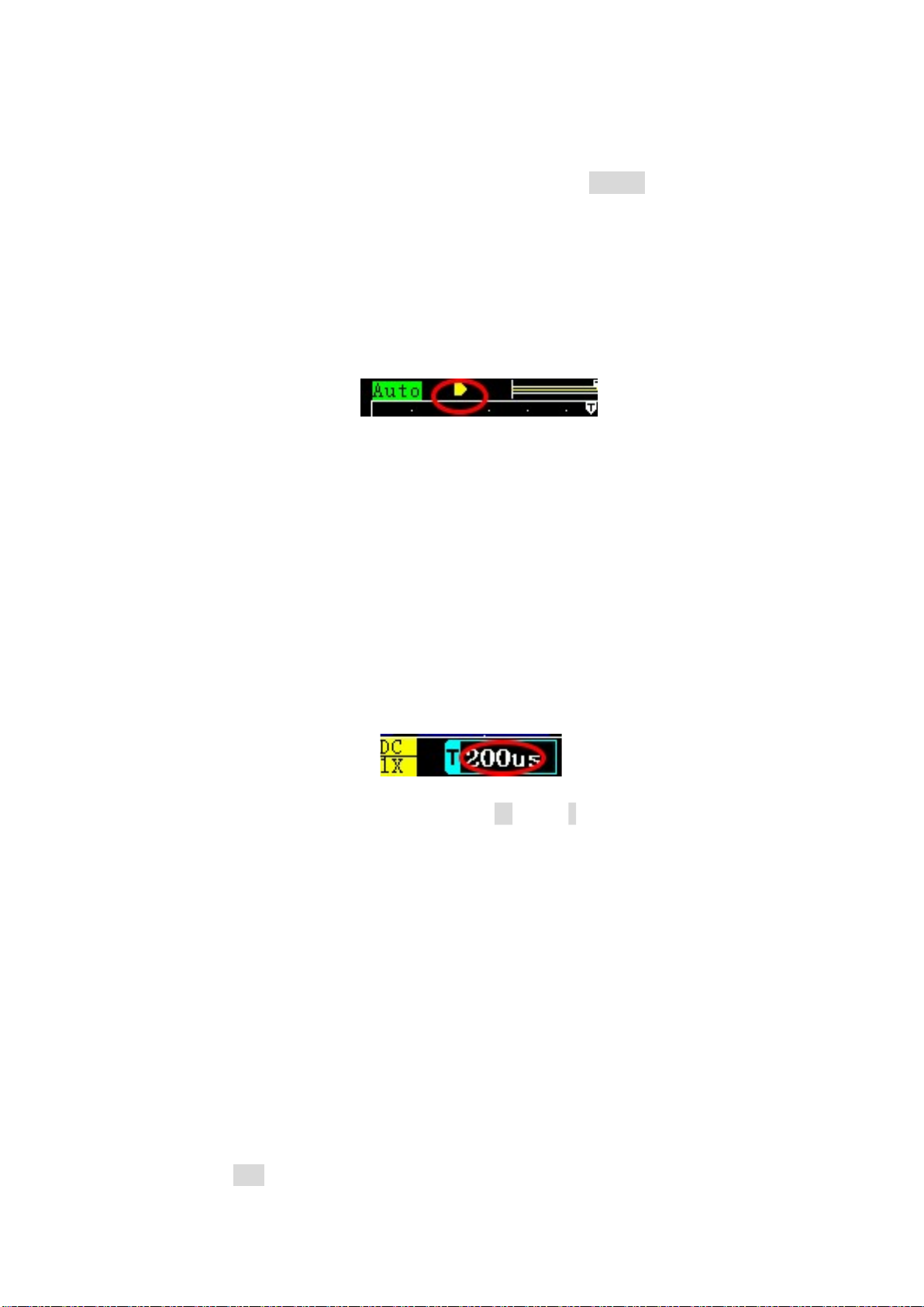
One-handed operation (not recommended). You can also long press the "mV"
buttons to switch between the "Waveform" or "Trigger Level". Pay attention to the
change of the arrow in the upper left corner, as shown below:
4 Horizontal system
4.1 Time base
The time base refers to the time represented by each grid in the horizontal
direction on the oscilloscope screen. There are 12 grids in the horizontal direction of
the oscilloscope. The sampling time that can be observed on the screen = " time base"
* 12.The user can estimate the signal period by observing how many grids a
waveform period occupies. For example, the current time base is 500us, and one cycle
of the signal occupies 2 grids,so the signal period is 1ms (1KHz).
The oscilloscope time base range is 5ns ~ 10s. The buttons for adjusting the time
base in the oscilloscope button panel are 'ns' and 's' button. When observing
high-frequency signals, you should press the 'ns' button to decrease the time base.
When observing low-frequency signals, you should press the 's' button Increase the
base gear.
What you need to know is that the sampling process of the oscilloscope is:
"Sampling">>"Processing" >> "Display"
When adjusted to a large time base, the screen waveform refresh will be slow
due to the longer time taken by the oscilloscope to sample the waveform. For example,
if the user adjusts to the 50ms time base, that is, the entire sampling time is at least
50msx12 = 600ms, the oscilloscope waveform refresh speed is reduced to less than 2
frames of waveform per second, which is normal.
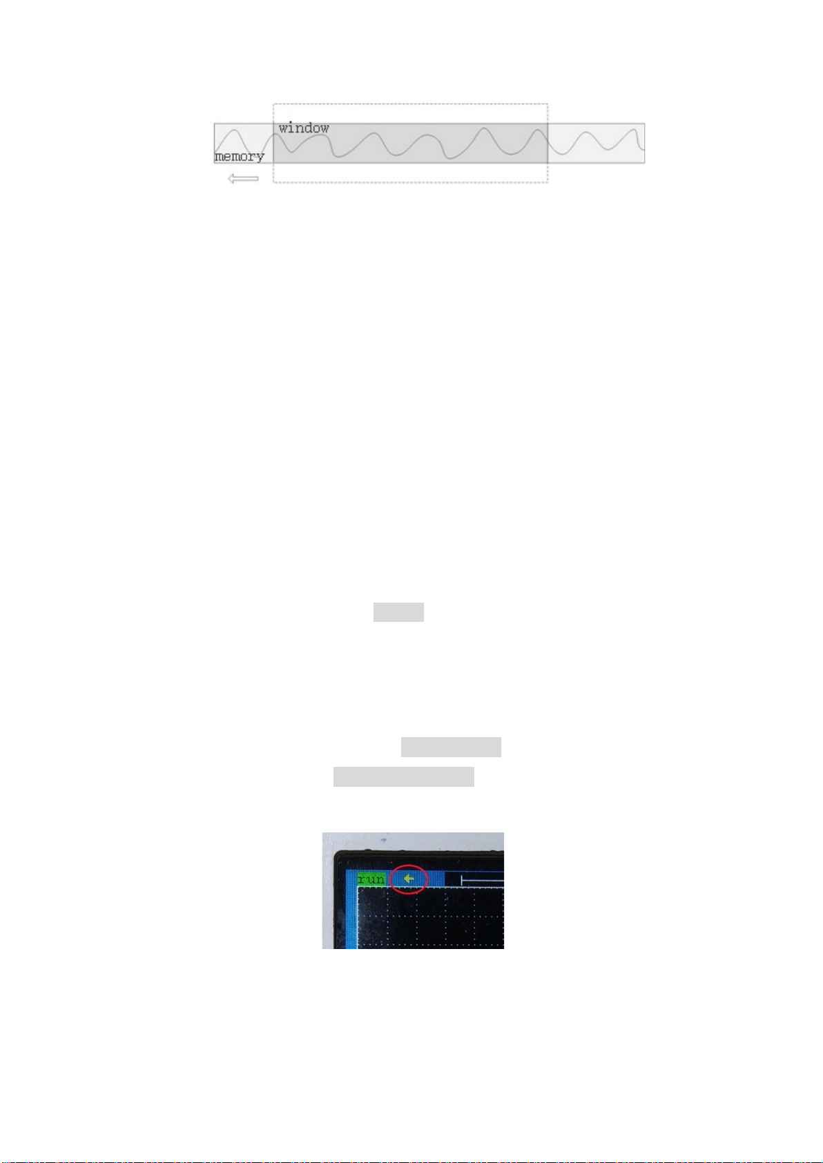
4.2 Horizontally moving waveform
In the stop mode, the user can move the waveform left and right.

9
5 Trigger system
About trigger
The oscilloscope will capture a frame of waveform only after the waveform
meets the pre-set conditions. This action of capturing the waveform according to the
conditions is the trigger.
What does trigger do?
1. Trigger can stabilize the waveform on the screen.
2. Capture the segment of the waveform you want to observe.
The trigger supported by the oscilloscope is edge trigger, including rising edge
trigger and falling edge trigger.
5.1 Trigger level
In edge trigger mode, a trigger condition occurs only when the waveform crosses
the trigger level. To adjust the trigger level:
1. Change "Trigger Level" to "Manual" in the menu.
2. Method 1:
Press and hold the Power key, and then click the up and down direction
buttons to adjust the trigger level.
Method 2:( Not recommended)
In the main window, make sure that the mark in the upper left corner of the
screen is the trigger level arrow(Thin left arrow), as shown in the figure:
If it is not this arrow, long press the “mV” button to switch.
Press the ↑↓buttons to move the trigger level up and down.
5.2 Trigger position
The default trigger position of the oscilloscope is in the middle of the screen. In

10
the running state, the user can move the trigger position by pressing the left and right
buttons.。The trigger position is shown on the screen as an arrow.
6 Operation Guide
6.1 POWER
In the shutdown state, long press the "POWER" button to turn on the machine,
and then release the button when the screen is on.
In the power-on state, long press the "POWER" button to shut down(about 4
seconds), and release the button after the screen goes out.
6.2 Charging
The upper right corner of the oscilloscope displays the current remaining
power. When the power is insufficient, use a USB cable to connect a
5V/1A/2A/4A adapter for charging, computer or mobile phone adapter is the best
choice.The charging current is about 700ma.
The LED at the bottom of the charging process is bright red, and the led turns
green when fully charged.
6.3 Vertical / Time base scale
Press the "mV" and "V" buttons to adjust the vertical sensitivity.
Press the "ns" and "s" buttons to adjust the time base.
6.4 Trigger Level
method 1:
Press and hold the Power key, and then click the up and down direction keys to
adjust the trigger level.
Method 2: (not recommended)
Long press the "mV button, when the arrow is a thin leftward arrow, it means
that the ↑↓ button can move the trigger level.
6.5 Auto
The auto function is a more common function in the oscilloscope. After the user
presses the "Auto" button, the oscilloscope will automatically adjust the time base and
vertical sensitivity so that the waveform is displayed in the middle of the screen.
Beginners can try to press the "Auto"button when they don't know how to adjust.

11
6.6 Run/stop
In the running state, click the "Run/Stop" button to stop the oscilloscope. After
stopping, the oscilloscope no longer performs sampling, and the user can observe the
last sampling data retained in the memory. Click the "Run/Stop" button in stop mode
to make the oscilloscope enter the running state.
6.7 50%
The function of 50% in the oscilloscope is to return the waveform to the middle,
including vertical offset, trigger position, and trigger level.
Operation method: Click the "xKey" button and select "50%".
6.8 Single
Single trigger means that after pressing the button, the oscilloscope samples a
frame of waveform and then stops. That is, only one frame of waveform is acquired
per click. It is important to note that there must be a trigger for this sampling. If there
is no trigger, the oscilloscope displays “wait” in the upper left corner of the
oscilloscope. This sampling is not completed until there is a waveform trigger.
Operation method: Click the "xKey" button and select "Single".
6.9 Reference waveform
The reference waveform is that the waveform of the previous frame is latched on
the screen for display.
The reference waveform is useful for a single-channel oscilloscope. For example,
when you want to compare the driving waveforms of two Mos-FETs, you can
measure the waveform of one of the Mos-FET first, then latch the waveform on the
screen, and then move the probe to measure Another Mos-FET, so that two driving
waveforms can be displayed on the screen at the same time for easy comparison.
Operation method: Click the "xKey" button and select "REF"
6.10 Screenshot
Click the "xKey" button–> "Save" to capture the current screen.
6.11 View images
Click the "xKey" button–> "View" to enter the Image View window. In this
window, the user can delete or browse historical screenshots.
Click the “Run/Stop” button to delete the current screenshots.
Click the "ok" button to zoom in on the waveform. After zooming in, click "ok"
to return to the homepage.

12
Click the "Menu" button to return to the oscilloscope window.
6.12 Generator
Long press the “Run/Stop” button to open the window of the signal generator,
The signal amplitude is 2.5V, the maximum frequency of the sine wave is 2MHz, and
the other waves are 2MHz.
Click the "Run/Stop" button to turn on/off the signal generator output.
Click the "50%/Power" button to reset the number to: 1.00Khz, 50%
Click the "mV" and "V" keys to switch the output waveform: sine wave, square
wave, triangle wave, etc.
Click "Ok" to confirm and exit.
Square wave and triangle wave can adjust the duty cycle, other waveforms do
not work.
Note: When the set frequency is greater than 1MHz, the square wave signal may
show small horizontal jitter.
6.13 Video output
The 3.5mm headphone jack at the bottom can output AV analog video signal ,
which can be connected to a TV or projector. Open Menu -> Set, and then long press
"Run/Stop" to enable video output. Disable if executed again.
6.14 Connect to PC
The screenshot pictures can be exported to a computer via a USB connection.
Operation method: Click "Menu" button to open the menu, switch to the "Set"
menu, and then long press the "ns" button. At this time, connect the computer through
the USB cable, and the computer will appear a U disk, which stores the user-stored
waveform pictures.
If you want to return to the oscilloscope window, you need to disconnect the
USB, and then restart the machine.
Warning:
This U disk is only for exporting pictures, please do not copy other files from the
computer to the U disk.

13
6.15 Cursor
Hold down the Power button and then click the “s” button to turn on/off the
horizontal cursor.
Press and hold the Power button and then click the “ns” button to turn on/off the
vertical cursor.
Press the left and right direction buttons directly to move the horizontal cursor 1
Press and hold the Power button and then press the horizontal direction buttons to
move the horizontal cursor 2. The same goes for the vertical cursor.
For the vertical cursor, the value of Y1 means: the voltage of the dotted line
above. The value of Y2 means: the voltage of the dotted line below. dY=Y1-Y2 is the
voltage difference between the two dotted lines.
7 Menu introduction
Click the "Menu" button to open / close the menu.
7.1 Channel
The channel menu includes two options, "Coupling" and "Probe".
The coupling method can be "DC coupling" and "AC coupling". DC coupling
passes the signal directly. AC coupling is equivalent to series connection with the
capacitor.
Probes are available in "1X" / "10X"/ "100X", this option corresponds to the
oscilloscope probe. When the probe is switched to the 10X position, this option
should be selected as "10X".
7.2 Measurement
There are 14 measurement options available, as shown below:
Frequency, Peak-to-Peak, Duty cycle, Amplitude, RMS, Average, Period, +Pulse
width, -Pulse width, Max, Min,Top, Base, -Duty cycle.

14
The difference between peak-to-peak and amplitude(AMP) is shown in the
figure above.
7.3 Trigger
There are Three options in the trigger menu: “Trigger Mode” / “Trigger Type”
and “Trigger level”.
Trigger Mode can be selected from "Auto" and "Normal".
For “Auto” mode, if a waveform trigger is detected, the waveform signal will be
used for triggering. If the oscilloscope cannot detect the trigger condition, it will
automatically force the trigger to display the waveform.
For “Normal” mode, the oscilloscope will not refresh the display until a
waveform trigger occurs. So there may be no waveform on the screen in this mode.
Trigger type includes rising and falling edges. Rising edge trigger means that
the waveform crosses the trigger level line upward, and a trigger condition occurs.
Trigger level include "automatic" and "manual".
"Automatic" is suitable for novices. The oscilloscope detects the waveform
position and amplitude and automatically sets the trigger level.
"Manual" is suitable for people who are familiar with the oscilloscope. When
using the “Single” function or the trigger mode is "Normal", you should use the
"manual" option. Under this option, the trigger level can be manually adjusted by the
user.
7.4 Display
In this menu you can set persistence / roll mode and brightness.
“Persistence” is to make the historical waveform remain on the screen for a
while and then disappear. Optional persistence options are: None, 1s, Infinite. When
Infinity is selected, the waveforms that have appeared on the screen will remain
forever and will not disappear.
“roll” is to display the waveform while sampling. Only when the time base is
greater than or equal to 200ms will the roll mode be entered. If roll is turned off, the
waveform will be displayed after one screen is sampled at any time base, resulting in
a long time before the screen is refreshed for large time base.
7.5 Aux
There are two options of "Calibration" and "FFT" in the auxiliary menu.
When the probe is removed, if there is a significant deviation between the
waveform position and the zero arrow position, it indicates that calibration is required.
Please remove the probe and USB cable before calibration, and then click the
"OK" button. The oscilloscope then starts self-calibration. Do not perform any
operation on the oscilloscope until it is completed. After completing the calibration,

15
restart the oscilloscope.
(Unless you confirm that the oscilloscope does have a large zero offset,
calibration is generally not recommended)
After the FFT option is turned on, it can perform FFT calculation on the screen
waveform and display the waveform after FFT. FFT display mode can be selected as:
"logarithmic", linear and "music" (music spectrum).
In this menu, long press the ↑ button to enter the overclocking mode (for
measuring 100M-120M signal), and press ↓ to return to the normal mode.
7.6 Settings
1. In this menu, you can set whether to shut down automatically. If you choose
to shut down automatically, the oscilloscope will automatically shut down 15
minutes after no button operation.
2. You can choose whether to turn on the sound.
3. Language selection: Chinese or English.
4. In this menu, long press the "ns" button to enter the usb connection state,
long press "s" to change the background color of the measure.
Parameters
Model DSO1511G Coupling AC/DC
Channels 1 AUTO Support
Screen size 2.4 inch Measurement
14 types
Resolution 320*240 Precision of V ±2%
Bandwidth 120M Reference Support
Sampling rate 500M Screenshot Support
Rise time <3ns Frequency ±0.01%
Storage depth
128Kbit Single Support
Impedance 1MΩ FFT Support
Time base 5ns – 10s Generator 0-2Mhz / 2.5V±0.1V
Ver sensitivity
10mV/div-10V/div 50% Support
Max voltae ±40V(x1)
±400V(x10)
Shell size width*hight* thickness
73 mm *93 mm *32mm
Trigger mode Auto/Normal Language CN/EN
Trigger type rise/fall Charging USB TypeC-5V 1A/2A/5A
Display mode YT / Roll
Persistence None/1s / ∞

16
Table of contents
Other ZEEWEII Test Equipment manuals