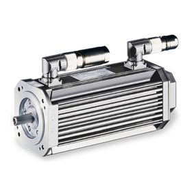
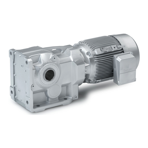
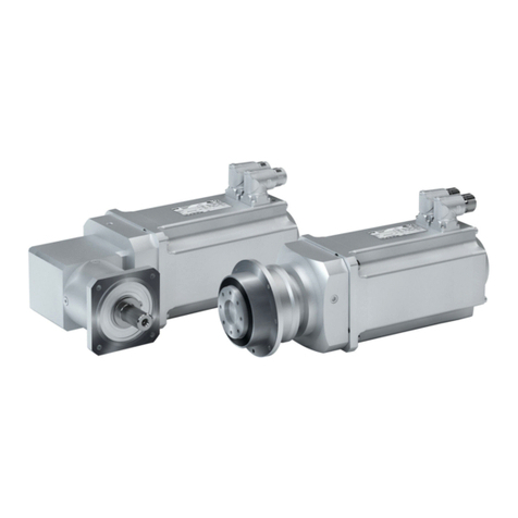
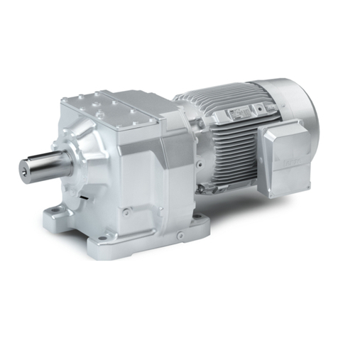
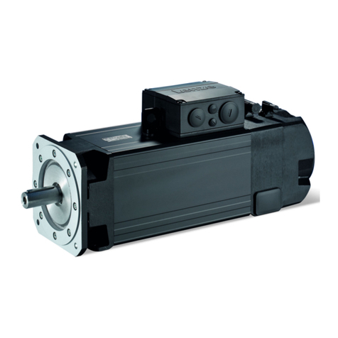
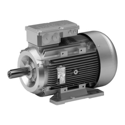
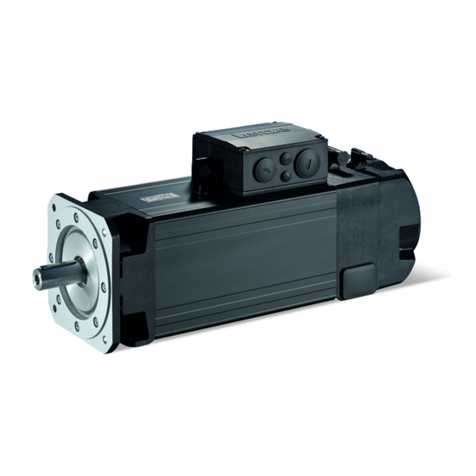
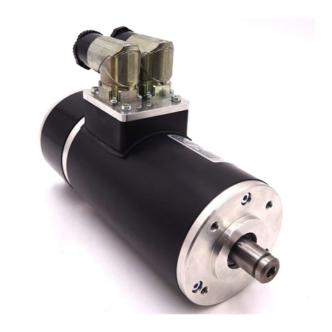
Lenze MDERA 056 V1 Series Quick start guide

Anschlussplan
Wiring diagram
Schéma de câblage
Esquema de conexiones
Schema di collegamento
MA 33.0005
.O6X
Ä.O6Xä
M....
MMA, MERA... V1
Drehstrommotoren
AC motors
Moteurs triphasés
Motores trifásicos
Motori trifase

MA 33.0005 DE/EN/FR/IT/ES 5.0 2
einschraubtiefe----(DUMMYSEITEVOR)---
Anschraubmaße für B14-Flansch
S
C
Screw-on dimensions for B-14 flange
Cotes de fixation pour bride B14
Medidas de atornillado para brida B14
Quota di avvitamento per flangia B14
cmax. s
[mm] [mm]
MDERA056 V1 FT65 11 M5
MDERA063 V1 FT75 14 M5
MDERA071 V1 FT85 14 M6
MDERA080 V1 FT100 16 M6
MDERA090 V1 FT115 14 M8
MDERA100 V1 FT130 19 M8
MDERA112 V1 FT130 21 M8
MDERA132 V1 FT165 22 M10
MMAN063 FT75 10 M5
MMAN071 FT85 10 M6
MMAN080 FT100 12 M6
MMAN080 FT130 16 M8
MMAN090 FT115 14 M8
MMAN090 FT130 16 M8
MMAN100 FT130 14 M8
MMAN112 FT130 16 M8
MHERA080FT100 15 M6
MHERA090FT115 16 M8
MHERA100FT130 18 M8
MHERA112FT130 19 M8
MHERA132FT165 23 M10

MA 33.0005 DE/EN/FR/IT/ES 5.0 3
einschraubtiefe----(DUMMYSEITEVOR)---
[Nm] ± 10%
M4 M5 M6 M8
2.2 3.5 4.5 -----
1.2 2.0 3.0 6.0
2.2 3.5 ----- -----

MA 33.0005 DE/EN/FR/IT/ES 5.0 4
einschraubtiefe----(DUMMYSEITEVOR)---

MA 33.0005 DE/EN/FR/IT/ES 5.0 5
einschraubtiefe----(DUMMYSEITEVOR)---

MA 33.0005 DE/EN/FR/IT/ES 5.0 6
KFZ_Zeichen_DE-anschluss-stillstandheizg
Lesen Sie zuerst diese Anleitung, bevor Sie mit den Arbeiten beginnen!
Diese Anleitung ist nur gültig zusammen mit der Gesamtdokumentation des
Grundgerätes und des Motors!
Tipp!
Informationen und Hilfsmittel rund um die Lenze-Produkte finden Sie im
Download-Bereich unter
http://www.Lenze.com
Gefahr!
Wenn Sie die folgenden grundlegenden Sicherheitsmaßnahmen missachten,
kann dies zu schweren Personenschäden und Sachschäden führen:
Hinweis!
Alle Farbenkennzeichnungen beziehen sich auf Lenze Systemleitungen!
Warnings!
Wichtige Hinweise zur Montage von Motoren mit Flansch in UL-approbierten
Anlagen:
Im Motorgehäuse befinden sich Gewindelöcher oder Durchgangsbohrungen.
ƒDiese Löcher dürfen nicht für die Montage von Füßen benutzt werden.
ƒDiese Motoren dürfen Sie nur fest und ohne Füße montieren.

MA 33.0005 DE/EN/FR/IT/ES 5.0 7
KFZ_Zeichen_DE-anschluss-stillstandheizg
Sicherheitshinweise
ƒ Lenze-Antriebs- und Automatisierungskomponenten ...
... ausschließlich bestimmungsgemäß verwenden.
... niemals trotz erkennbarer Schäden in Betrieb nehmen.
... niemals technisch verändern.
... niemals unvollständig montiert in Betrieb nehmen.
... niemals ohne erforderliche Abdeckungen betreiben.
... können während und nach dem Betrieb - ihrer Schutzart entsprechend - spannungs-
führende, auch bewegliche oder rotierende Teile haben. Oberflächen können heiß sein.
ƒ Alle Vorgaben der beiliegenden und zugehörigen Dokumentation beachten.
Dies ist Voraussetzung für einen sicheren und störungsfreien Betrieb sowie für das Er-
reichen der angegebenen Produkteigenschaften.
ƒ Alle Arbeiten mit und an Lenze-Antriebs- und Automatisierungskomponenten darf
nur qualifiziertes Fachpersonal ausführen.
Nach IEC 60364 bzw. CENELEC HD 384 sind dies Personen, ...
... die mit Aufstellung, Montage, Inbetriebsetzung und Betrieb des Produkts vertraut
sind.
... die über die entsprechenden Qualifikationen für ihre Tätigkeit verfügen.
... die alle am Einsatzort geltenden Unfallverhütungsvorschriften, Richtlinien und Ge-
setze kennen und anwenden können.
ƒ Lebensgefährliche Spannung an den Leistungsanschlüssen, auch bei abgezogenem
Stecker: Restspannung >60 V!
ƒ Vor Arbeiten an den Leistungsanschlüssen Motor und wenn vorhanden
Antriebsregler unbedingt vom Netz trennen und warten, bis der Motor stillsteht
(Spannung bei drehendem Motor an den Kontakten).
ƒ Verbrennungsgefahr!
– Während des Betriebs heiße Oberflächen bis 140 °C! Berührschutz vorsehen.
ƒ Verletzungsgefahr durch drehende Welle!
– Vor Arbeiten am Motor warten bis Motor stillsteht.
ƒ Ausführung mit Stecker:
– Stecker niemals unter Spannung ziehen! Der Stecker kann sonst zerstört werden.
– Vor Abziehen des Steckers Spannungsvorsorgung abschalten bzw. Antriebsregler
sperren.

MA 33.0005 DE/EN/FR/IT/ES 5.0 8
KFZ_Zeichen_DE-anschluss-stillstandheizg
Montagehinweis
ƒ Zum Transport Traghilfen benutzen!
ƒ Nicht auf die Welle schlagen! Motor kann zerstört werden! Abtriebselemente nur
über Gewinde in der Motorwelle montieren, mit Abziehwerkzeug demontieren.
Kupplung fest anziehen.
ƒ Motor sicher befestigen, für ungehinderte Belüftung sorgen.
ƒ Überwurfmuttern der Stecker fest anziehen.
ƒ Motor sorgfältig erden, Verdrahtung kontrollieren.
ƒ Schirme der Motorleitung großflächig am Motor und am Antriebsregler auflegen.
Stop!
Maximal zulässige Anschraubtiefe bei B14-Flansch beachten, 2!
Elektrischer Anschluss
Hinweis!
ƒFür den sicheren Betrieb sind die Anzugsmomente mit einer Toleranz von
+- 10% einzuhalten (3).
Anschluss Fremdlüfter über Fremdlüfterklemmenkasten/Motorklemmenkasten
Fremdlüfter 3~
Klemmenbrett / Klemme Bedeutung Hinweis
U1 Anschluss an L1 - Netz Drehrichtung beachten! Bei falscher
Drehrichtung L1 - L2 vertauschen
V1 Anschluss an L2 - Netz
W1 Anschluss an L3 - Netz
Fremdlüfter 1~
Klemmenbrett /Klemme Bedeutung Hinweis
U1 Anschluss an L1- Netz
V1 / U2 Anschluss an N - Netz

MA 33.0005 DE/EN/FR/IT/ES 5.0 9
KFZ_Zeichen_DE-anschluss-stillstandheizg
Leistungsanschlüsse am Klemmenbrett
Eintourige Motoren Polumschaltbare Motoren
ΥΔ
MT_MXXXX_001.iso/dms
Spannungsumschaltbare Motoren Legende
Υ
ΥΥ L1/L2/L3 Leistungsanschluss
TB1/TB2 Thermokontakt (TKO)
Niedrige Drehzahl
Hohe Drehzahl
ΥΥ Niedrige Spannung
ΥHohe Spannung
PE-Anschluss (optional)
Anschluss Temperaturüberwachung
Klemmenleiste / Klemmenbrett
Bedeutung Bezeichnung nach
EN 60034-8
Hinweis
Thermokontakt TKO TB1 max. 250 V ~
max. 1.6 A ~
TB2
Kaltleiter PTC TP1
TP2
Temperatursensor +KTY R1 Polarität beachten
Temperatursensor -KTY R2
Klemmenbrett oder Klemme für alle Thermofühler möglich.

MA 33.0005 DE/EN/FR/IT/ES 5.0 10
KFZ_Zeichen_DE-anschluss-stillstandheizg
Anschluss Rückführsystem
Resolver
Klemme Bezeichnung Bedeutung
B1
B2
+Ref
-Ref
Transformatorwicklungen (Referen-
zwicklungen)
B3 nicht belegt
B4
B5
+COS
-COS
Ständerwicklung Cosinus
B6
B7
+SIN
-SIN
Ständerwicklung Sinus
B8 nicht belegt
Inkrementalgeber / Sin-Cos-Absolutwertgeber mit Hiperface
Klemme Bezeichnung Bedeutung
B1
B2
+U
B
GND
Versorgung +
Masse
B3
B4
A/+COS
A/ Ref cos
Spur A / Prozessdatenkanal
Spur A invers / Prozessdatenkanal
B5
B6
B/-SIN
B/Refsin
Spur B / Prozessdatenkanal
Spur B invers / Prozessdatenkanal
B7
B8
Z / Daten +
Z / Daten -
Nullspur / Pararmeterkanal + RS485
Nullspur invers / Pararmeterkanal - RS485
B10 1) Schirm Geh. Inkrementalgeber Schirm
1) Die Klemme ist nicht belegt bei Option B-seitig isoliertem Motorlager!
Hinweis!
ƒSignalleitung geschirmt ausführen.
ƒAuf beidseitige Schirmanbindung achten.

MA 33.0005 DE/EN/FR/IT/ES 5.0 11
KFZ_Zeichen_DE-anschluss-stillstandheizg
Anschluss Bremse
Klemme Bedeutung Zusatz
~Bremse wechselstromerregt (Gleichrich-
ter) Anschluss an L1 - Netz
~
123456
-~~+
Anschluss an N - Netz
+Anschluss an Bremse
-Anschluss an Bremse
Schaltkontakt gleichstromseitiges
Schalten
BD1 Bremse gleichstromerregt Gleichstromanschluss
BD2
MS1 Mikroschalter Bremse Lüftkontrolle Wechselkontakt (schwarz)
MS2 Öffner (braun)
MS4 Schließer (blau)
MS1 Mikroschalter Bremse Verschleißkon-
trolle Wechselkontakt (schwarz)
MS2 Öffner (blau)
MS4 Schließer (braun)
MS1 Mikroschalter Bremse Handlüftung Wechselkontakt (schwarz)
MS2 Öffner (blau)
MS4 Schließer (grau)
Anschluss Stillstandsheizung (Option)
Klemmenleiste
Bezeichnung nach EN 60034-8 Hinweis!
HE1 24 V
HE2
HE3 230 V
HE4
HE5 110 V
HE6

MA 33.0005 DE/EN/FR/IT/ES 5.0 12
KFZ_Zeichen_EN-anschluss-stillstandheizg
Please read these instructions before you start working!
These instructions are only valid together with the complete documentation
of the standard device and the motor!
Tip!
Information and auxiliary devices related to the Lenze products can be found
in the download area at
http://www.Lenze.com
Danger!
Disregarding the following basic safety measures may lead to severe personal
injury and damage to material assets!
Note!
The colour coding scheme refers to Lenze system cables!
Warnings!
Important installation instructions for flange-mounted motors
The operating instructions indicates that the motor housing has threaded
holes or through holes.
ƒThese holes may not be used to install feet.
ƒMotor mounting is only allowed as fixed installation without feet.

MA 33.0005 DE/EN/FR/IT/ES 5.0 13
KFZ_Zeichen_EN-anschluss-stillstandheizg
Safety instructions
ƒ Lenze drive and automation components ...
... must only be used for the intended purpose.
... must never be operated if damaged.
... must never be subjected to technical modifications.
... must never be operated unless completely assembled.
... must never be operated without the covers/guards.
... can - depending on their degree of protection - have live, movable or rotating parts
during or after operation. Surfaces can be hot.
ƒ All specifications of the corresponding enclosed documentation must be observed.
This is vital for a safe and trouble-freeoperation and for achieving the specified product
features.
ƒ Only qualified skilled personnel are permitted to work with or on Lenze drive and
automation components.
According to IEC 60364 or CENELEC HD 384, these are persons ...
... who are familiar with the installation, assembly, commissioning and operation of the
product,
... possess the appropriate qualifications for their work,
... and are acquainted with and can apply allthe accident prevent regulations, directives
and laws applicable at the place of use.
ƒ Hazardous voltage at the power terminals, even if the plug is removed: residual
voltage >60 V!
ƒ Before carrying out work on the power connections, always disconnect the motor
and controller, if any, from the mains and wait until the motor is at standstill
(voltage at the contacts when the motor is rotating).
ƒ Risk of burns!
– Hot surfaces up to 140 °C during operation! Provide protection against contact.
ƒ Risk of injury due to rotating shaft!
– Before working on the motor ensure that the motor is at standstill.
ƒ Design with plug:
– Never disconnect plug when energised! Otherwise, the plug can be destroyed.
– Disconnect power supply or inhibit controller prior to disconnecting the plug.

MA 33.0005 DE/EN/FR/IT/ES 5.0 14
KFZ_Zeichen_EN-anschluss-stillstandheizg
Notes for mounting
ƒ Use an appropriate means of transport and lifting equipment!
ƒ The shaft must not be exposed to knocks or bumps! Motor can be destroyed! Drive
elements must be mounted on the motor shaft via the threading. An extracting
device must be used when dismounting. Fasten coupling securely.
ƒ Fasten motor and ensure unimpeded ventilation.
ƒ Tighten coupling ring of connector.
ƒ Motor must be carefully earthed, check cabling.
ƒ Extensive shielding of motor cable on motor and controller.
Stop!
Observe the maximally permissible length of engagement for B14 flanges,
2!
Electrical connection
Note!
ƒIn order to ensure a safe operation, comply with the tightening torques
with a tolerance of
+- 10% (3).
External blower connection via external blower terminal box/motor terminal box
External blower 3~
Terminal board/terminal Meaning Note
U1 Connection to L1 - mains Observe direction of rotation! In
case of incorrect rotation,
interchange L1 - L2
V1 Connection to L2 - mains
W1 Connection to L3 - mains
External blower 1~
Terminal board /
terminal
Meaning Note
U1 Connection to L1- mains
V1 / U2 Connection to N - mains

MA 33.0005 DE/EN/FR/IT/ES 5.0 15
KFZ_Zeichen_EN-anschluss-stillstandheizg
Power connections on the terminal board
Single-rotation motors Pole-changing motors
ΥΔ
MT_MXXXX_001.iso/dms
Dual-voltage motors Legend
Υ
ΥΥ L1/L2/L3 Power connection
TB1/TB2 Thermal contact (TKO)
Low speed
High speed
ΥΥ Low voltage
ΥHigh voltage
PE connection (optional)
Connection of temperature monitoring
Terminal strip / terminal board
Meaning Designation in accordance
with EN 60034-8
Note
Thermal contact TCO TB1 Max. 250 V ~
Max. 1.6 A ~
TB2
PTC thermistor TP1
TP2
Thermal sensor +KTY R1 Observe polarity
Thermal sensor -KTY R2
Terminal board or terminal possible for all thermal sensors

MA 33.0005 DE/EN/FR/IT/ES 5.0 16
KFZ_Zeichen_EN-anschluss-stillstandheizg
Connection of feedback system
Resolver
Terminal Designation Meaning
B1
B2
+Ref
-Ref
Transformer windings (reference
windings)
B3 not assigned
B4
B5
+Cos
-Cos
Stator winding cosine
B6
B7
+Sin
-Sin
Stator winding sine
B8 not assigned
Incremental encoder / sin/cos absolute value encoder with Hiperface
Terminal Designation Meaning
B1
B2
+U
B
GND
Supply +
Mass
B3
B4
A/+COS
A/ Ref cos
Track A / process data channel
Track A inverse / process data channel
B5
B6
B/-SIN
B/Refsin
Track B / process data channel
Track B inverse / process data channel
B7
B8
Z / data +
Z/ data -
Zero track / parameter channel + RS485
Zero track inverse / parameter channel - RS485
B10 1) Shield - housing Shield - incremental encoder
1) The terminal is not assigned if insulation at N-end shield of the motor has been selected!
Note!
ƒShield signal cable.
ƒConnect shield on both sides.

MA 33.0005 DE/EN/FR/IT/ES 5.0 17
KFZ_Zeichen_EN-anschluss-stillstandheizg
Brake connection
Terminal Meaning Add-on
~AC-excited brake (rectifier) Connection to L1 - mains
~
123456
-~~+
Connection to N - mains
+Brake connection
-Brake connection
Switching contact, DC switching
BD1 Brake, DC operated DC connection
BD2
MS1 Brake microswitch, release control Two-way switch (black)
MS2 NC contact (brown)
MS4 NO contact (blue)
MS1 Brake microswitch, wear control Two-way switch (black)
MS2 NC contact (blue)
MS4 NO contact (brown)
MS1 Brake microswitch, manual release Two-way switch (black)
MS2 NC contact (blue)
MS4 NO contact (grey)
Space heater connection (option)
Terminal block
Designation acc. to EN 60034-8 Note!
HE1 24 V
HE2
HE3 230 V
HE4
HE5 110 V
HE6

MA 33.0005 DE/EN/FR/IT/ES 5.0 18
KFZ_Zeichen_FR-anschluss-stillstandheizg
Veuillez lire attentivement ce manuel avant toute action !
Ce manuel n’est valable qu’avec la documentation générale de l’appareil de
base et du moteur !
Conseil !
Toutes les informations relatives aux produits Lenze peuvent être téléchargées
sur notre site à l’adresse suivante :
http://www.Lenze.com
Danger !
Le non-respect des consignes fondamentales de sécurité suivantes peut
entraîner des blessures et des dommages matériels graves.
Remarque importante !
Les désignations de couleur se rapportent aux câbles système de Lenze !
Warnings !
Instructions d’installation importantes pour moteurs à flasque
Les instructions de mise en service indiquent que la carcasse du moteur
disposed’orificesfiletésoud’orificesdepassage.
ƒCes orifices ne doivent pas être utilisés pour monter des pattes.
ƒLe montage du moteur n’est autorisé qu’en installation fixe et sans pattes.

MA 33.0005 DE/EN/FR/IT/ES 5.0 19
KFZ_Zeichen_FR-anschluss-stillstandheizg
Consignes de sécurité
ƒ Les composants d’entraînement et d’automatisation Lenze ...
... doivent exclusivement être utilisés conformément à leur fonction.
... ne doivent jamais être mis en service si des dommages sont décelés.
... ne doivent jamais être modifiés d’un point de vue technique.
... ne doivent jamais être mis en service s’ils ne sont pas montés intégralement.
... ne doivent jamais être mis en service sans le capot obligatoire.
... peuvent - selon l’indice de protection - contenir des pièces sous tension, en
mouvement ou en rotation. Les surfaces peuvent être brûlantes.
ƒ Respecter les consignes et les indications contenues dans la documentation
concernée.
Il s’agit de la condition préalable pour garantir un fonctionnement sûr et fiable et pour
obtenir les caractéristiques du produit indiquées.
ƒ Les travaux réalisés avec et au niveau des composants d’entraînement et
d’automatisation Lenze ne doivent être exécutés que par un personnel qualifié et
habilité.
Selon les normes CEI 60364 ou CENELEC HD 384, ces personnes doivent ...
... connaître parfaitement l’installation, le montage, la mise en service et le
fonctionnement du produit.
... posséder les qualifications appropriées pour l’exercice de leur activité.
... connaître toutes les prescriptions pour la prévention d’accidents, directives et lois
applicables sur le lieu d’utilisation et être en mesure de les appliquer.
ƒ Une tension mortellement dangereuse circule dans les raccordements de puissance,
même lorsque le connecteur est retiré : tension résiduelle > 60 V !
ƒ Avant de manipuler les raccordements de puissance, couper impérativement le
moteur (et le variateur éventuel) du réseau et patienter jusqu’à ce que le moteur soit
à l’arrêt (contacts sous tension lorsque le moteur est en marche).
ƒ Risque de brûlure !
– En service, la température de surface peut atteindre 140°C ! Prévoir une protection
contre les contacts accidentels !
ƒ Risque de blessure en cas de contact avec l’arbre tournant !
– Avant de manipuler le moteur, patienter jusqu’à l’arrêt.
ƒ Version avec connecteur :
– Ne jamais retirer le connecteur sous tension ! Dans le cas contraire, le connecteur
risque d’être endommagé.
– Avant de retirer le connecteur, couper l’alimentation ou bloquer le variateur de
vitesse.

MA 33.0005 DE/EN/FR/IT/ES 5.0 20
KFZ_Zeichen_FR-anschluss-stillstandheizg
Remarque concernant le montage
ƒ Utiliser les dispositifs d’aide au transport !
ƒ Evitertoutchocsurl’arbre!Lemoteurpourraitêtreendommagé!Monterles
éléments de transmission sur l’arbre en utilisant impérativement les trous taraudés.
Pour les démonter, utiliser l’outil d’extraction. Veiller à ce que l’accouplement soit
bien serré.
ƒ Bien fixer le moteur ; veiller à ce que la ventilation ne soit pas entravée.
ƒ Bien serrer les écrous-raccords des connecteurs.
ƒ Relier le moteur à la terre avec soin ; contrôler le câblage.
ƒ Appliquer une surface de contact importante entre les blindages du câble moteur et
le moteur/variateur.
Stop !
Tenir compte de la profondeur de serrage max. admissible pour les brides B14,
2!
Raccordement électrique
Remarque importante !
ƒ
Respecter les couples de serrage indiqués (tolérance +- 10 ) afin d’assurer
un fonctionnement sûr (3).
Raccordement du motoventilateur via une boîte à bornes de motoventilateur/une boîte
à bornes de moteur
Raccordement triphasé du motoventilateur
Plaque à bornes/borne Description Remarque importante
U1 Raccordement au réseau L1 Attention au sens de rotation ! Si le
sens de rotation est incorrect,
inverser L1 et L2.
V1 Raccordement au réseau L2
W1 Raccordement au réseau L3
Raccordement monophasé du motoventilateur
Plaque à bornes/borne Description Remarque importante
U1 Raccordement au réseau L1
V1 / U2 Raccordement au réseau N
This manual suits for next models
18
Table of contents
Languages:
Other Lenze Engine manuals

Lenze
Lenze M Series User manual

Lenze
Lenze SDS Series User manual

Lenze
Lenze g500-S Guide

Lenze
Lenze GST Series User manual

Lenze
Lenze m850 Technical manual

Lenze
Lenze M55BH063S04 Guide

Lenze
Lenze g500-S Guide

Lenze
Lenze MCS 06C60 Guide

Lenze
Lenze L-force GST User manual

Lenze
Lenze Smart Motor m300 Technical manual

Lenze
Lenze g500-H45 Technical manual

Lenze
Lenze MCM Series Guide

Lenze
Lenze g500-B User manual

Lenze
Lenze IE2 Guide

Lenze
Lenze g500-H Technical manual

Lenze
Lenze MCA Series Guide

Lenze
Lenze IE3 g500-H Technical manual

Lenze
Lenze MD KS Series User manual

Lenze
Lenze g500-B Technical manual

Lenze
Lenze G7 Series Guide