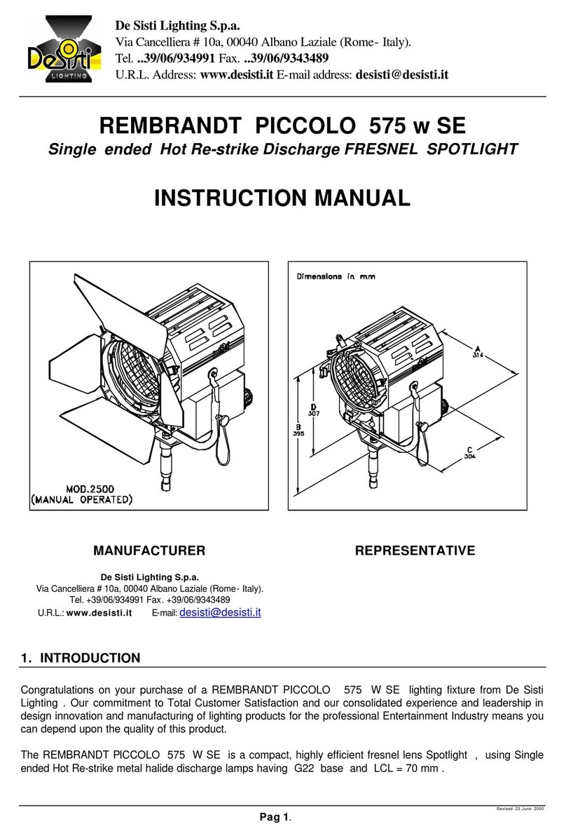
Desisti REMBRANDT PICCOLO 1.200 w SE User manual

Revised 23 June 2000
Pag 1.
REMBRANDT PICCOLO 1.200 w SE
Single ended Hot Re-strike Discharge FRESNEL SPOTLIGHT
INSTRUCTION MANUAL
MANUFACTURER REPRESENTATIVE
De Sisti Lighting S.p.a.
Via Cancelliera # 10a, 00040 Albano Laziale (Rome- Italy).
Tel. +39/06/934991 Fax. +39/06/9343489
U.R.L.: www.desisti.it E-mail: desisti@desisti.it
1. INTRODUCTION
Congratulations on your purchase of a REMBRANDT PICCOLO 1200 W SE lighting fixture from De Sisti
Lighting . Our commitment to Total Customer Satisfaction and our consolidated experience and leadership in
design innovation and manufacturing of lighting products for the professional Entertainment Industry means
you can depend upon the quality of this product.
The REMBRANDT PICCOLO 1200 W SE is a compact, highly efficient fresnel lens Spotlight , using Single
ended Hot Re-strike metal halide discharge lamps having G38 base and LCL = 107 mm .
NOTE : Also available , on special requests , either a pole operated version , or a version with connector of
type German STD M1 .
2. YOKE AND ACCESSORIES ASSEMBLY
De Sisti Lighting S.p.a.
Via Cancelliera # 10a, 00040 Albano Laziale (Rome- Italy).
Tel. ..39/06/934991 Fax. ..39/06/9343489
(MANUAL OPERATED)
MOD.2510

Revised 23 June 2000
Pag 2.
3. SAFETY INSTRUCTIONS
ÂProfessional use: This luminaire has been designed for professional use and must be operated by
qualified personnel only. Not for residential use.
ÂGrounding: This luminaire is used only with De Sisti ballast . THE BALLAST MUST BE GROUNDED .
ÂElectrical connections :
•DO NOT CONNECT THIS LUMINAIRE DIRECTLY TO THE ELECTRICAL MAINS .
•The supply cord ends with a dedicated connector . By this connector the luminaire must be connected
to PROPERLY RATED DE SISTI BALLAST , magnetic or electronic .
•The wiring diagram of lamp house and connector is shown herebelow
Working conditions
ÂWorking Position Lighting fixture: Max. Tilting ±90 ° from horizontal Lamp: any
( see lamp catalogue )
ÂAmbient Temperature, ta+45° C Max
Top Back Sides Front
ÂMinimum distances from
inflammable surfaces 0,5 m. 0,2 m. 0,2 m. 3,0 m.
The luminaire should never be OPERATED close to inflammable materials. The ones indicated in the above
table are the minimum distances recommended.
Other requirements for safe use are:
MOD.2510 (MANUAL OPERATED)

Revised 23 June 2000
Pag 3.
A. Do not cover the apertures of the luminaire housing. They are essential for correct ventilation. Do not use
on the floor. It reduces the ventilation.
B. Use only original accessories and spares from De Sisti Lighting.
C. Before hanging the luminaire ensure that the suspension point (or the stand) is properly rated to accept
the luminaire weight.
D. A suitable secondary safety suspension device (safety cable, chain or equivalent) must be fitted between
the suspension point and the eyelet at the front of the body .
WARNING : DO NOT MOUNT THE LUMINAIRE ON A NORMALLY FLAMMABLE SURFACE .
WARNING : UV RISK . The lamps usable on the luminaire emit an amount of UV RADIATION very
dangerous for human health if not properly shielded .
For this reason the luminaire MUST NEVER BE USED IN THE SITUATIONS WHEN DIRECT LIGHT
EMISSION FROM THE LAMP CAN OCCURR ( ex : Damaged or no front lens , no mirror , damaged
internal baffles , additional aperture on the housing )
4. INSTALLATION INSTRUCTIONS
Before connecting the luminaire to the ballast ensure that:
A – The ballast is compatible with the luminaire .
B - The ballast is suitable for the electrical mains ( Voltage & Frequency ) .
C – The ballast is properly earthed ( use the ground continuity test present on De Sisti ballast ) and the
ballast main switch is in OFF position .
D - The lamp fitted :
Âis among the usable lamps ( see point 6 or check with your De Sisti dealer )
Â( for magnetic ballast ) has the nominal power equal to the ballast.
Â(for De Sisti Electronic Ballast , single or dual power ) has nominal power not higher than the
Max of the ballast .
E – The front safety shields against the lamp explosion are present and in good condition.
They consist of a fresnel lens plus wire guard . The fresnel lens is made of borosilicate
untoughened glass D= 150 mm , thickness 5 mm typ ( 3 mm min ) , compliant to DIN 15560 . The
wire guard is a mesh 25 mm x 25 mm( or smallaer ) , wire D=0,8 mm typ , made by nickel coated or
stainless steel .
After connection to the ballast , follow the ballast instruction to operate on the system .
WARNING : SHIELDS, LENSES SAFETY OR DICHROIC GLASSES SHALL BE CHANGED IF THEY HAVE
BECOME VISIBLY DAMAGED TO SUCH AN EXTENT THAT THEIR EFFECTIVENESS IS IMPAIRED, FOR
EXAMPLE BY CRACKS OR DEEP SCRATCHES.
THE LUMINAIRE SHALL ONLY BE USED COMPLETE WITH ITS PROTECTIVE SHIELD .
5. LAMP INSTALLATION AND REPLACEMENT
The following procedure should be adopted:
A - Ensure the luminaire is electrically isolated from the power supply.
B -WAIT AT LEAST 5 MINUTES FROM SWITCHING OFF to avoid risk of injury from possible lamp
explosion. Then open lens door .
WARNING: AFTER THE ABOVE MENTIONED TIME THE LAMP MAY STILL BE VERY HOT, USE
PROPER THERMAL PROTECTION (EG. GLOVES).
C - Check that the new lamp is of the correct type. SEE WARNING FOR INSTALLATION ( ITEM 4 – D ) .
D - Replace the lamp taking good note of the following:
•do not touch the bulb with bare-hands; oil and grease can contaminate the bulb surface and then
reduce the performance and the lamp life.
•the plastic cover which protects the lamp should not be removed until after fitting.
•should the bulb become dirty due to hand contact or for any other reason, it can be cleaned with a
cloth moistened with alcohol.
•instructions by lamp manufacturers must be followed .
E - Ensure that the lens door is securely closed.
WARNING : THE LAMP MUST BE REPLACED IF IT HAS BECOME DAMAGED OR DEFORMED .
6. CHARACTERISTICS AND PERFORMANCE DATA
DESCRIPTION VALUE

Revised 23 June 2000
Pag 4.
ÂAmperage See lamp data ( from ballast to head ) or ballast manual ( supply to ballast)
ÂMAX Ignition voltage ( hot lamp ) ≅50 KV
BALLAST TYPE CONNECTION
DEB 1,2 K Direct
DEB 575/1,200 W Direct to 1200 w socket
ÂConnections to ballast
( Standard version )
Magnetic 1,2 K Direct
Standard Version Special Version ( * )
ÂConnector type 7 Pin 24-2 Male with ring nut -
Type : Bayonet 3 ramps
7 pin ( 6 M - 1 F ) with threaded
ring nut – Type : German std
M1
ÂLamp Holder G 38
ÂPower Cable ( from fixture to ballast ) 7 x 1,5 mm2- Rubber , for rough service
ÂProtection Class Class 1– ground connection required through ballast
ÂProtection Type IP 22
ÂMax Housing surface temperature 150 °C
ÂWeight of Fixture 8,5 Kg ( MO )
4 leaf 8 leaf
ÂWeight of barndoor
0,63 kg. 0,85 kg.
Seat Diameter Ring Diameter
ÂSize of Barndoor ring
192 mm. 190 mm.( ≅7”1/2)
Seat x scrims Scrim Dia.
ÂSize of scrims and color frame
187 mm 185 mm (≅7”1/4)
( * ) = Special version with German std M1 connector are available only on special request and shall be used with special ballast
and extension cables for connector compatibility .
USABLE LAMPS
Manufacturer
Model
OSRAM HMI 1200 w / SE
PHILIPS MSR HR 1200 w
Other manufacturers may be used as long as they meet completely the technical specifications of the above lamps
7. PERIODIC INSPECTION
A. The condition of the internal wiring insulation shall be inspected and tested every 500 working hours and
at least once a year. This frequency may need to be increased if rough or unknown (eg. rental) treatment is
incurred. Replace only with original De Sisti Lighting spare parts. Non-original cables may not withstand the
thermal and mechanical conditions of use
B. The lamp condition must be checked every 100 working hours. In order to avoid explosion the lamp
should be changed if it has become damaged or deformed. Follow the instructions supplied by the lamp
manufacturer.
C. Check the condition of the safety shield (see section 4 : Installation Instructions) before every use.
D. High Voltage components : High voltage wires ( from igniter to lampholder ) , their external shield , and
the lampholder must be inspected every 100 working hours and at least once a year . They shall be
replaced as soon as any mechanical cracking , even if minor , or visible thermal damage is discovered.
E. The behaviour of the safety microswitch ( on door closure ) must be checked every 250 working hours
and at least ones a year .
F . The correct status , functionality and tightening of the lensdoor assembly ( including hinge and door
catch ) must be checked once a year , or more frequently depending on the use , to ensure that the
accessories are correctly retained and the door properly fixed and retained when closed .
G. Check the condition of the mirror every 250 working hours and replace as soon as it becomes cracked
or opaque . It is essential for good light performance and correct thermal behaviour .
8. SAFETY STANDARDS
Europe: The product conforms the Applicable European Directives &
Standards
America: the product conforms NEC & UL stds.
ÂLow Voltage Directive: 73/23/EEC (as amended by 93/68/EEC)
ÂEMC Directive: 89/336/EEC (as amended by 92/31/ EEC and 93/68/EEC)
ÂEuropen Standards:: EN 60598-2-17, EN 60598-1 , EN 55015
UL Standard : 1573
Table of contents
Other Desisti Spotlight manuals

Desisti
Desisti SOFT LED 2 XL Vari-White User manual

Desisti
Desisti SUPER LED F10 VW User manual

Desisti
Desisti Muses of Light AUREA User manual

Desisti
Desisti REMBRANDT PICCOLO 575 w SE User manual

Desisti
Desisti PICCOLETTO DIM User manual

Desisti
Desisti Muses of Light CLIO User manual

Desisti
Desisti SUPER LED F7rp User manual

Desisti
Desisti Muses of Light ERATO User manual
Popular Spotlight manuals by other brands

rolson
rolson 60781 user manual

Wagan
Wagan Brite-Nite R600 user manual

LeuchtKraft
LeuchtKraft PARL-7730 instruction manual

Eurosep Instruments
Eurosep Instruments G2L Series quick start guide

Code 3
Code 3 CW3000 Series installation instructions

Good Earth Lighting
Good Earth Lighting G19920-WH-I instructions