Desjoyaux GR.I 181 Installation guide

INSTALLATION AND OPERATING GUIDE
JANUARY 2018
FILTRATION UNIT GR.I 181
www.desjoyau .com
Tél. 04.77.36.12.12
PISCINES DESJOYAUX - 42 Avenue Benoît Fourneyron CS 50280 - 42484 La Fouillouse cede (France)
TECHNICALINSTRUCTIONS - FILTRATION UNIT GR.I 181
Revision 1.0 of 19/01/18
Translation of the original instructions

TECHNICAL INSTRUCTIONS - FILTRATION UNIT GR.I 181
Revision 1.0 of 19/01/18
This guide contains the instructions required to install and use your
GR.I 181 filtration unit
for private domestic pools.
We recommend that you carefully read the various sections of this guide and file this document in a safe place for future
reference. Keep in mind all the safety requirements and recommendations below.
This fil ra ion sys em complies wi h he requiremen s of European Low Vol age Direc ives (2014/35 / EU),
EMC (2014/30 / EU) and RoHS (2011/65 / EU).
Compliance has been checked in accordance wi h EN/IEC 60335-1, EN/IEC 60335-2-41 and EN/IEC 60598-2-18 (curren edi ions).
This filtration system also complies with the European standards for private domestic pools N EN 16582 and N EN 16713.
Electrical connection must be made by a qualified electrician and must comply with standards and/or regulations in force in the country
where the unit is being installed.
When installed in accordance with the recommendations below, this filtration system meets the requirements of electrical standards N
C15-100, HD 60364 and IEC 60364 (current editions).
In keeping with the EU directive on electronic waste (WEEE), this product should not be disposed of with household waste
but must be collected separately.
or more information, please contact your local authorities or your distributor.
Safety instructions and warnings:
The use of a massage hose connected to the water discharge pipe presents a potential danger when the jet is directed at a person above
the water level (risk of eye injury).
Any modification to the positioning of valves or the pump type may cause a variation of flow and result in an increase of the suction
speed.
In case of doubt concerning the pump or the filtration system, contact your installer.
This device is not intended for use by children
under the age of 8 or individuals with limited
physical, sensory or mental capacities or limited
experience/knowledge, unless they are
supervised by an individual responsible for their
safety or receive instructions from the latter as
to how the device should be used and
understand the risks involved. Children should
not play with the appliance. Cleaning and
maintenance should not be performed by
children without supervision.
Made in rance.
Translation of the original instructions

TECHNICAL INSTRUCTIONS - FILTRATION UNIT GR.I 181
Revision 1.0 of 19/01/18
Contents :
1. Presen a ion of he GR.I 181 fil ra ion uni 22
2. General views 23
3. Technical specifica ions and ins ruc ions prior o he ins alla ion and opera ion of he GR.I 181 fil ra ion uni 24
4. Lis of ools required for assembly. 25
5. GR.I 181 ins alla ion and opera ing ins ruc ions 25
5.1 - Suppor masonry 25
5.2 - Posi ioning he fil ra ion uni 26
5.3 - Liner ins alla ion 26
5.4 - Commissioning of he GR.I 181 fil ra ion uni 26
5.5 - GR.I 181 fil ra ion uni win er shu -down opera ions 27
6. De ailed views 28
6.1 - GR.I 181 fil ra ion uni - S andard version 28
6.2 - GR.I 181 fil ra ion uni - By-pass op ion 28
6.3 - GR.I 181 fil ra ion uni - Sal elec rolyser op ion 29
6.4 - GR.I 181 fil ra ion uni - Elec ric hea er op ion 29
7. General elec rical ins ruc ions 30
7.1 - Elec rical connec ions 30
7.2 - Burying of elec rical cables 30
7.3 - No es 30
7.4 - Connec ion diagram 31
7.5 - Elec ric hea er connec ion diagrams 32
8. Spo ligh lamp change procedure on he GR.I 181 fil ra ion uni 33
9. Ins alla ion of fil ra ion accessories 34
10. Technical burs 35
11. Nomencla ure 36
TECHNICAL INSTRUCTIONS - FILTRATION UNIT GR.I 181
Revision 1.0 of 19/01/18
1. Presentation of the GR.I 181 filtration unit
● The e a e seve al standa d ve sion of this filt ation system:
► GR.I 181 P18 ve sion: GR.I 181 unit equipped with a P18 pump:
- Single-speed pump, moto : powe consumption 450W (50 o 60Hz)
- Total assigned powe with the spotlights: 595W
► GR.I 181 P25 ve sion: GR.I 181 unit equipped with a P25 pump:
- Single speed pump, abso bed powe 1205W (50 o 60Hz)
- Total assigned powe with lighting spotlights: 1426W
► GR.I 181 PBi ve sion: GR.I 181 unit equipped with a PBi pump:
- Dual-speed pump, moto : low-speed powe : 370W / high-speed powe : 2100W
- Total assigned powe with the spotlights: 2410W
● Each standa d ve sion can be equipped with optional adaptation piping fo :
- a by-pass heating system, o
- a salt elect olyse , o
- an elect ic heate .
● Configu ation of the GR.I 181 filt ation unit
The GR.I 181 filt ation unit consists of the following components:
● Ope ating p inciple
The pump d aws wate th ough the skimme opening on the side of the filt ation unit. The wate is immediately filte ed th ough the
filt ation bag (6 o 15 mic ons).
The wate is d awn in by the pump and then discha ged into the pool.
This DESJOYAUX Piscines filt ation system includes all the t aditional system functions.
Its efficiency, coupled with easy maintenance, will p ovide complete satisfaction.
● Cha acte istics of the GR.I 181 filt ation unit
- Rapid installation, easy to use, eliable and economical
- Su face wate intake
- Co osion-p oof mate ials
- Ve y little head loss
- Mixing of su face wate and at depth by gy ation
- Built-in spotlights
- Filt ation th ough suction
- Easy se vicing
- Reduced afte -sales se vice
- High deg ee of filt ation, 6 o 15 mic ons
- Exceptional cleanability of the filte bags by wate jet o , if necessa y, by washing machine.
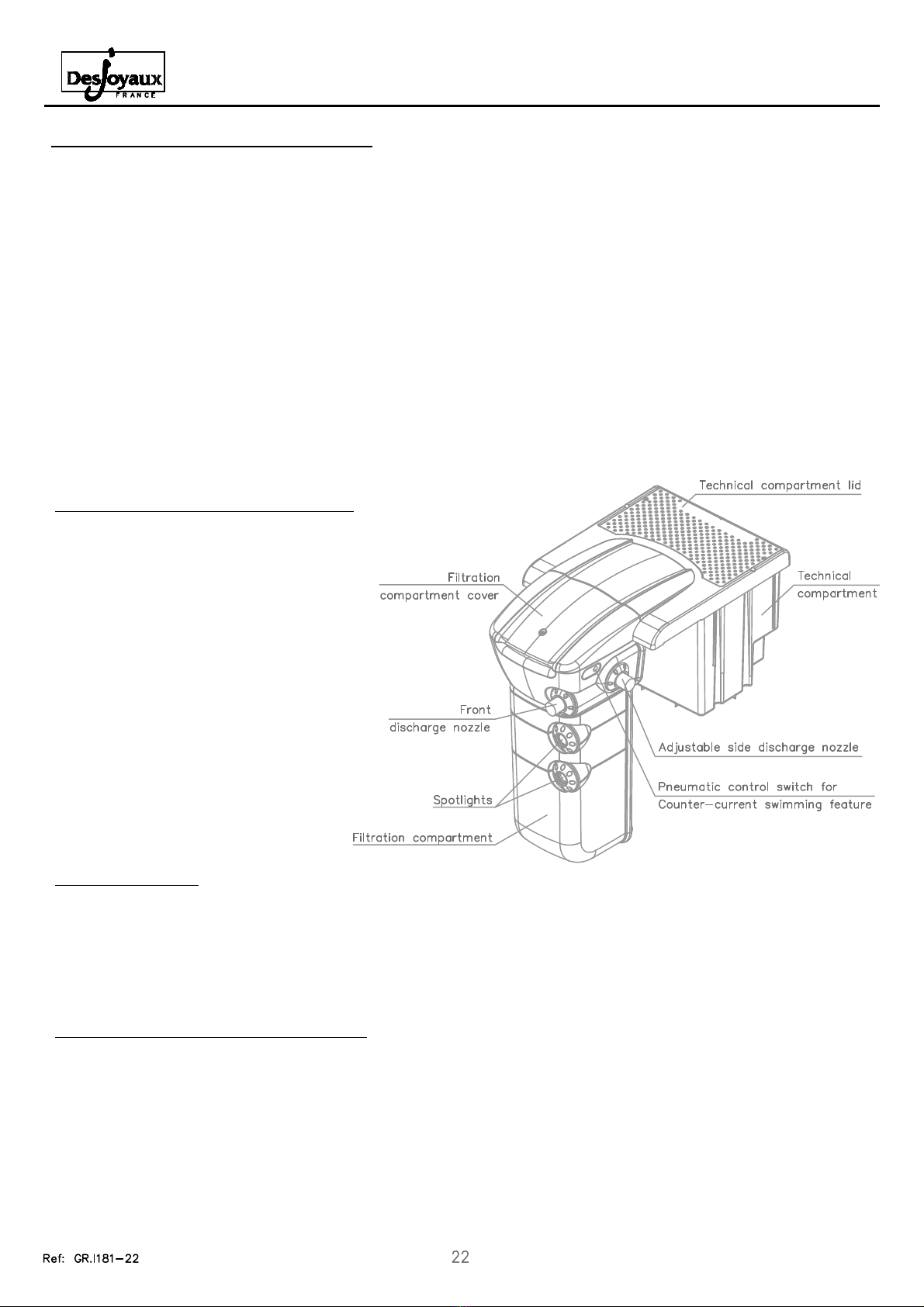
- an imme sed "filt ation compa tment"
equipped with 2 spotlights, skimme
opening, and the f ont and side (adjustable)
discha ge nozzles. The filt ation
compa tment contains the filte element
and the connecting pipes with the technical
compa tment.
- a "technical compa tment", inse ted into a
mason y housing at the edge of the pool
deck, which houses the pump and its
connecting pipes, the t ansfo me fo the
two spotlights and the elect ical connection
box.
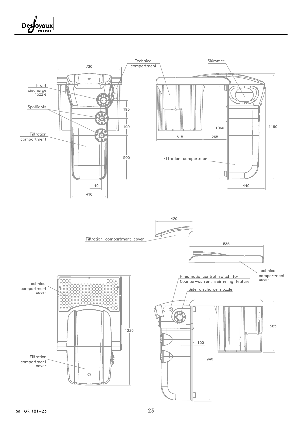
2. General views
TECHNICAL INSTRUCTIONS - FILTRATION UNIT GR.I 181
Revision 1.0 of 19/01/18
FRONT VIEW
TO VIEW
LEFT SIDE VIEW
RIGHT SIDE VIEW

TECHNICAL INSTRUCTIONS - FILTRATION UNIT GR.I 181
Revision 1.0 of 19/01/18
3. Technical specifications and instructions prior to the installation and operation of the GR.I 181 filtration unit
The GR.I 181 fil ra ion uni is equipped wi h fea ures designed o op imise ins alla ion and opera ion.
● Herme ic echnical compar men
A perfec seal is ensured be ween he swimming pool and he echnical compar men by means of herme ic pipe feed hroughs.
CAUTION: he cover of he echnical compar men mus be securely closed a all imes by means of i s 2 moun ing screws.
● Masonry
Only 2 suppor columns are required o suppor he fil ra ion uni .
Refer o he ins alla ion ins ruc ions hereaf er.
● Spo ligh s
Turn on the spotlights only once they are fully immersed.
NEVER use alcohol or solven s o clean he spo ligh . Use only soapy wa er.
● Pump removal
Before disconnec ing and removing he pump, he connec ing pipes mus be drained by unscrewing he wo purge plugs loca ed on he
suc ion and discharge lines in he fil ra ion compar men .
Do no forge o securely igh en hese 2 plugs before reins alling he pump.
● Ins alla ion of op ional piping
- If your ins alla ion requires a by-pass, order he piping ha is specially adap ed o he GR.I 181.
All pipes passing hrough he echnical compar men wall mus be made herme ic by means of specially designed herme ic
feed hrough elemen s.
In addi ion, if you foresee he ins alla ion of by-pass hea ing equipmen a a la er ime, we s rongly recommend ha he necessary
connec ing pipes be ins alled during he cons ruc ion phase.
- If your ins alla ion is equipped wi h an elec ric hea er, order he piping ha is specially adap ed o he GR.I 181.
- The s andard discharge piping mus be modified if he sal elec rolyser sys em is ins alled.
Refer o he elec rolyser's ins alla ion manual.
● Buried pipes
Buried pipes (par icularly when fi ing a bypass) mus be subjec ed o a pressure s reng h es before and af er backfilling (NF EN 16
713-2) o ensure ha hey have no suffered any damage during he ins alla ion.
● Locking he fil ra ion compar men cover
We also recommend ha he fil er compar men cover be kep closed using he ¼- urn lock in order o secure access o he skimmer
baske and rea men produc s.
● Fil ering bags
Use only Desjoyaux fil ering bags

TECHNICAL INSTRUCTIONS - FILTRATION UNIT GR.I 181
Revision 1.0 of 19/01/18
4. List of tools required for assembly.
● Not s pplied
Phillips screwdriver
Flathead screwdriver
B ilder’s r le
Spirit level
Adj stable wrench
Cement
Sand
Solid breeze blocks
D50 red sheath for electric cables
Vac m cleaner for laying the liner
Desjoya x m lti-cond ctor cable
Pipe wrench 17 or 19 mm (depending on p mp)
Allen wrench 5
5. GR.I 181 installation and operating instructions
5.1 - S pport masonry
When the pool's masonry and filtration nit location is being b ilt, constr ct two parallel tiers of blocks, at the filtration nit and parallel
to the str ct re (a maxim m of 40cm from the o tside of the pool wall), p to 54cm from the pper edge of the pool (top of the liner
lock).
● For the filtration nit's
electrical connection,
remember to ro te Ø50
cond it to j st behind
the nit's 2 s pport
col mns.
● For the by-pass piping
connection, also ro te 2
Ø50 PVC pipes to the
back of nit's 2 s pport
col mns.
● D ring the backfill operation, remember not to backfill aro nd the filtration nit above the s pporting blocks.
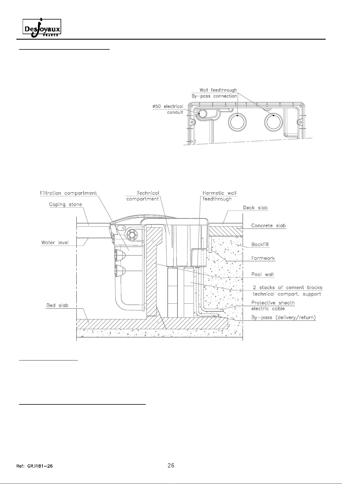
TOP VIEW - TECHNICAL COMPARTMENT
● Place a form around the technical com artment (using rigid cardboard, for exam le) which will rovide sufficient s ace to remove the
unit from its location. This formwork must remain in lace until the deck has been laid around the swimming ool.
● Finish backfilling around the filtration unit, and finalise the ool masonry work (installation of the co ing stones and ool deck area).
TECHNICAL INSTRUCTIONS - FILTRATION UNIT GR.I 181
Revision 1.0 of 19/01/18
5.2 - Positioning the filtration unit
● At the to of the two stacks of blocks, our a concrete levelling course 51.5cm from the to of the liner lock in order to finish off the
filtration unit su ort base.
● Position the filtration unit. Make sure that the unit rests correctly on to of the ool wall. Remove the technical com artment cover
and check that the to of the unit is level.
● Slide the Ø50 electrical conduit through the
o ening rovided at the back of the GR.I 181
technical com artment.
● If necessary, glue the 2 PVC by- ass
connecting i es in the two feedthroughs
rovided in the bottom of the technical
com artment.
5.3 - Liner installation
● CAUTION: The GR.I 181 filtration unit must be removed in order to install the liner.
● The installation of the liner requires no s ecial commentary.
5.4 - Commissioning the GR.I 181 filtration unit
● The filtration unit must be ut into service once the installation of your ool is com leted and at the start of each season.
● Install the filtration unit on the wall of the ool. Care must be taken so as not to damage the liner.
● Finish filling the ool to the u er 2/3 of the skimmer window.
● Before installing the um in the technical com artment, the um 's turbine must be turned manually via the um 's inlet o ening
(19mm tubular elbow wrench for the PBi um , 17mm for the P18 um ).

TECHNICAL INSTRUCTIONS - FILTRATION UNIT GR.I 181
Revision 1.0 of 19/01/18
● P ace the fi tration pump inside the technica compartment.
● Connect the intake ine to the pump's intake opening by tightening the 2¾" connecting nut - remember to fit the O-ring in p ace.
● Connect the intake ine with the f exib e s eeve and the two Ø63 c amps provided.
● Fi the body of the fi tration pump with water through the discharge opening.
5.5 - GR.I 181 filtration unit winter shut-down operations
● Position the ground fau t circuit interrupter (GFCI) to "OFF".
● Turn the circuit breakers inside the box to "OFF".
● Turn the switches inside the box to "OFF".
● Unscrew the two purge p ugs ocated in the suction and discharge ines in the fi tration compartment.
● Unscrew the cover's 2 retaining screws and open the technica compartment.
● Unscrew the Ø63 and Ø75 c amps on the pump's connecting ines and remove the two intake and discharge ines by unscrewing the
pump's 2 connecting nuts.
Be carefu not to ose the 2 O-rings.
● Using a screwdriver, open the connection box and unp ug the pump and transformer connectors.
● Remove, drain and store the pump in a dry area, far away from ch orinated products.
● Unscrew (2 screws) and remove the connection box from the technica compartment.
● Remove the technica compartment power supp y cab e through the opening provided for this purpose (without removing the p ug or
cab e g and).
● If a by-pass heater connecting pipe is insta ed, unscrew the nuts from the 2 by-pass wa feedthroughs at the bottom of the technica
compartment.
● Remove the GR.I 181 fi tration unit from its masonry housing and store it in a ocation which is protected from inc ement weather.
● P ace the power supp y cab e in the connection box. Fit the winter storage covers on the box in order to sea the unused openings.
● C ose the connection box secure y. The box shou d be eft in the technica compartment's masonry housing unti such time as the
GR.I 181 fi tration unit is put back into service.
Refer to the operating manua for further information concerning swimming poo shut down (winterisation) procedures.
● Connect the discharge ine to the pump's discharge opening by tightening the 2¾" connecting nut - remember to fit the O-ring in
p ace.
● Connect the discharge ine with a Ø75mm co ar using the No. 5 A en wrench (not provided).
● REMEMBER TO SECURELY TIGHTEN THE TWO PURGE BUTTONS ON THE INTAKE AND DISCHARGE LINES OF THE
FILTRATION COMPARTMENT.
● Have a e ectrica connections performed by a qua ified e ectrician (see instructions regarding the e ectrica connections).
● Insta the fi tering bag (see insta ation of accessories).
● Initiate fi tration by setting the switch on "MANU" (on the e ectrica contro pane ) and a ow it to operate for 2 or 3 days.
● CAUTION: before c osing the technica compartment cover, check for eaks on a pipe connections.
● After 2-3 days of fi tration, program the fi tration period on the contro timer.
● Position the switch on "AUTO" so that fi tration is carried out according to the desired programming schedu e and refer to the user's
manua for further information concerning fi tration time adjustment and water treatment operations.
TECHNICAL INSTRUCTIONS - FILTRATION UNIT GR.I 181
Revision 1.0 of 19/01/18
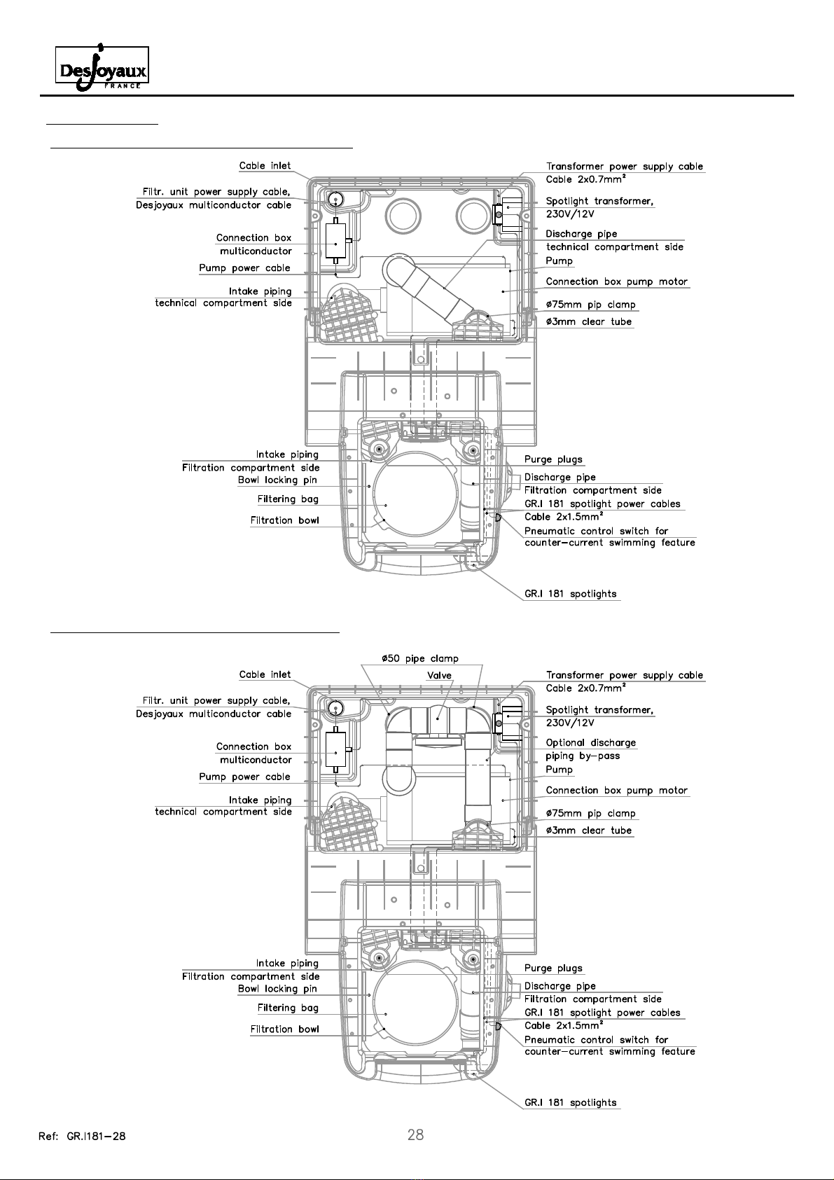
6. Detailed views
6.1 - GR.I 181 filtration unit - Standard version
6.2 - GR.I 181 filtration unit - By-pass option

TECHNICAL INSTRUCTIONS - FILTRATION UNIT GR.I 181
Revision 1.0 of 19/01/18
6.3 - GR.I 181 filtration unit - Salt electrolyser option
6.4 - GR.I 181 filtration unit - Electric heater option

TECHNICAL INSTRUCTIONS - FILTRATION UNIT GR.I 181
Revision 1.0 of 19/01/18
7. General electrical instructions
7.1 - Electrical connections
Electrical connection must be made by a qualified electrician and must comply with standards and/or regulations in force in
the country where the unit is being installed.
When installed in accordance with the recommendations below, this filtration system meets the requirements of electrical standards
NF C15-100, HD 03 4 and IEC 03 4 (current editions).
- Herme ic elec rical boxes shall be ins alled ou side he zone of pro ec ion, ha is a a dis ance grea er han 3.5m from any loca ion
around of he swimming pool.
- All of he connec ions in he connec ion boxes mus be re igh ened.
- A 16A circui breaker mus be ins alled in series a he head of he power supply line of he fil ra ion uni 's elec rical box (upline from
he GFCI).
- Refer o he elec rical diagrams below concerning he elec rical connec ions.
7.2 - Burying of electrical cables
- Under a pa h or sidewalk, cables should be buried a a minimum dep h of 0.85 me re.
- In o her cases, he minimum dep h is 0.5 me re.
- If he cables are no rou ed hrough condui , red warning ne ing mus be placed above i (Be advised, cer ain ypes of cables can be
buried wi hou having o be rou ed hrough condui ).
7.3 - Notes
- The cover of he echnical compar men which gives access o he elec rical componen s (pumps, ransformer) mus be locked down
wi h he screws provided for his purpose.
- Prior o main enance or servicing in he echnical compar men , disconnec he mains power supply o he uni .
- The power supply o he pump is single-phase; only cer ain hea ers can be run on hree-phase curren .
- The pump is equipped wi h a single-phase P18 mo or, he black wire No. 6 (refer o he fil ra ion elec rical box) is no used. Simply
leave i connec ed o he 4-pin female connec or in he mul iconduc or connec ion box.
- The power supply mus be grounded:
- in France, i mus be of accep able value and i s resis ance mus be measured periodically;
- in Belgium, he ground connec ion mus have a value of 30 ohms (for domes ic ins alla ions).
IMPORTANT NOTE:
The GFCI (30mA) in:
- the filtration box;
- the electric heater / blower differential boxe ,
mu t be te ted periodically (at lea t once per month).
The GFCI mu t trip when the te t button i pre ed.
- Thi te t mu t be performed when power i upplied to the GFCI;
- If the GFCI doe not trip, di connect the power upline and call a qualified electrician.

7.4 - Connection diagram
TECHNICAL INSTRUCTIONS - FILTRATION UNIT GR.I 181
Revision 1.0 of 19/01/18
FILTRATION ELECTRICAL CONTROL
NOTE: If t e P18 motor is in single speed mode, t e black wire No.6 serves no purpose. T is s ould be left connected to t e 4-pin
female connector located in t e multiconductor connection box.
FILTRATION ELECTRICAL
MULTICONDUCTOR CONNECTION BOX
FILTRATION ELECTRICAL CONTROL PANEL
CONTROL PANEL
PANEL WIRING SCHEME
Important: T e maximum allowable breaking capacity at 230V is 4.5kA (for domestic applications). T e installer must modify t e
breaking capacity of t e protective devices if t e installation requires t is.
TECHNICAL INSTRUCTIONS - FILTRATION UNIT GR.I 181
Revision 1.0 of 19/01/18
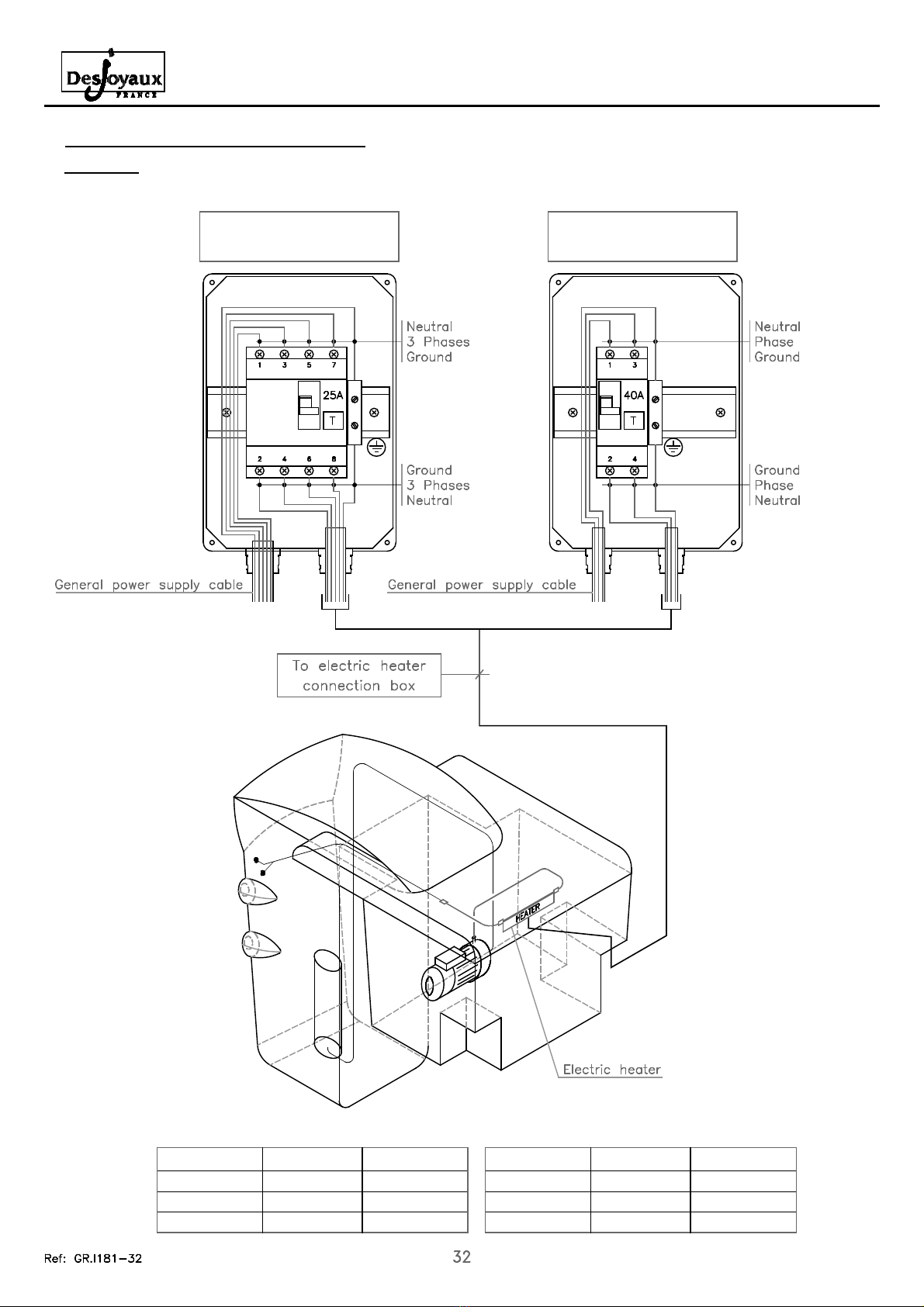
7.5 - Electric heater connection diagrams
BREAKER
1 kW heater
9kW heater
6kW heater
THREE PHASE
0A
16A
16A
5x .5mm²
5x .5mm²
5x4mm²
Cable size
THREE-PHASE HEATER
POWER SUPPLY BOX
BREAKER
50A
3 A
SINGLE PHASE
3x6mm²
3x4mm²
Cable size
SINGLE-PHASE HEATER
POWER SUPPLY BOX
6kW heater
9kW heater
CAUTION: the electric heater requires that a second power cable be installed, in addition to the multiconductor cable
required for the filtration and lighting system (see cable size below).

TECHNICAL INSTRUCTIONS - FILTRATION UNIT GR.I 181
Revision 1.0 of 19/01/18
8. Spotlight lamp change procedure on the GR.I 181 filtration unit
Only he 12-vol , 50-wa BT D.50 60° halogen lamps can be ins alled.
● Disconnec from he ransformer o he elec rical panel.
● Disconnec he spo ligh 's power supply cable in he ransformer connec ion box.
● Loosen he corresponding cable gland in he echnical compar men , hen pull he spo ligh 's power cable in he fil ra ion
compar men .
● Unclip he spo ligh from he fil ra ion compar men by urning i approxima ely 1/4 urn in order o disengage he re aining abs.
● Remove he spo ligh wi h i s power supply cable.
● Unscrew he collar + in ermedia e piece assembly o separa e he body.
● Remove he glass window, while being careful no o lose he gaske .
● Remove he lamp.
● Ins all a new lamp while being ex remely careful o correc ly inser he elec ric socke on o he lamp base.
● Check o ensure ha he gaske is in good condi ion and no pinched, hen replace he glass.
● Tigh en he collar + in ermedia e piece on he body. When igh ening, make sure ha he window is correc ly cen red in he base of
he housing. Tigh en o ensure ha he gaske is sligh ly fla ened.
● Inser he power supply cable, hen secure he spo ligh on he fil er compar men .
● In roduce he power cable in o he echnical compar men hrough he cable gland provided for his purpose.
● Reconnec he spo ligh 's power supply cable in he ransformer connec ion box.
● Af er urning he spo ligh on for he firs ime, make sure ha no air bubbles are presen . Bubbles are an indica ion ha he uni is
leaking. If bubbles are no ed, remove he spo ligh again and check he gaske and he condi ion of glass lens.
CAUTION: Do not use alcohol or solvents to clean the spotlight. Use only soapy water.
FRONT VIEW
COMPLIES WITH SWIMMING POOL LIGHTING STANDARD: NF EN 60598-2-18
TO BE USED ON Y IN THE CASE OF IMMERSION IN WATER
OPERATES ON Y WITH A 50VA SAFETY TRANSFORMER, MINIMUM
CROSS-SECTION A-A
- Max. power: 50W
- Vol age: 12V ac
- IP X8
TECHNICAL INSTRUCTIONS - FILTRATION UNIT GR.I 181
Revision 1.0 of 19/01/18
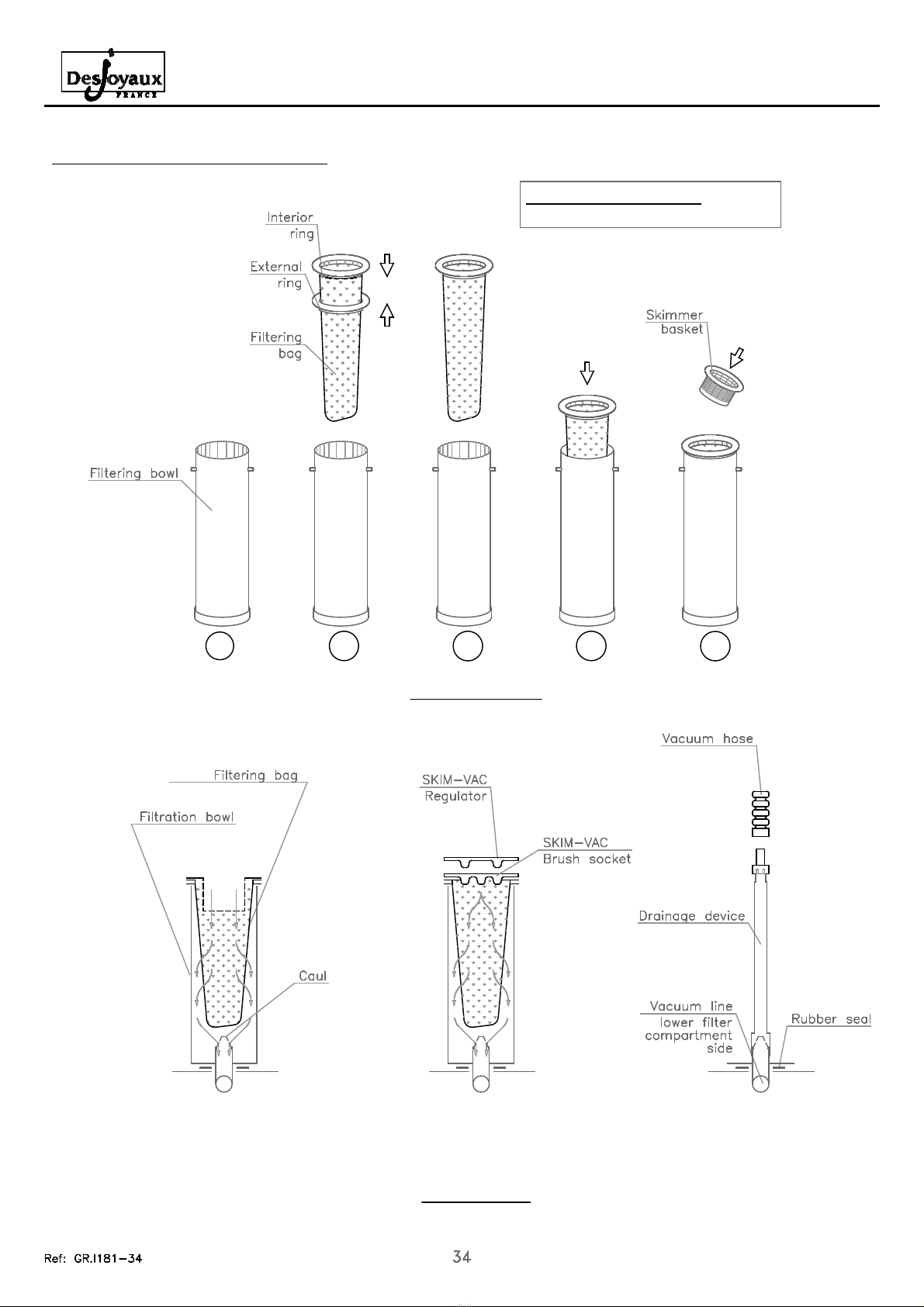
9. Installation of filtration accessories
POOL BOTTO CLEANING
OPERATION
INSTALLATION
FILTRATION
1 2
POOL DRAINAGE
53 4
Identification of filter bags:
Refer to the labels on the filter bags.
TECHNICAL INSTRUCTIONS - FILTRATION UNIT GR.I 181
Revision 1.0 of 19/01/18
10. Technical Burst
Révision 0.5 of 1 /01/ 018 [07/06 -> ]
OPTIONAL PIPINGS
4
65
66
58
34
8
44
9
61
4
41
40
39
37
35
38
36
3 6
48
50
45
46
55
56
64
5 45
46
68
67
55
56
64
54
47
53
6
59
8
9
57
43333130
7
6
5
70
69
3
13
14
15
11
16
60
17 13
14
15
1
60
18
7
6
0
63
4
1
3
51
10
71 71
10
75
7
TECHNICAL INSTRUCTIONS - FILTRATION UNIT GR.I 181
Revision 1.0 of 19/01/18
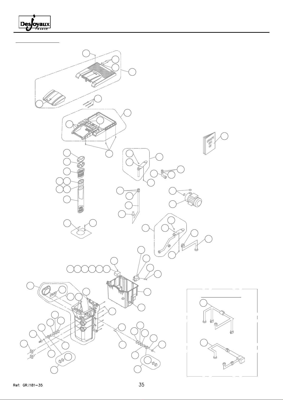
11. Nomenclature
Révision 0.5 of 1 /01/ 018 [07/06 -> ]
Item Description Qty Code
47 CLAMP FLEXIBLE D 75 MM 1 09 37
4 SEAL BOTTOM BOWL D75 MM 1 09761
49 ALLEN WRENCH 5 MM 1 90067
50 PIPE INT LW FILT GR.I-PF.I 1 0-
GR.I 1 1 1 95220
51 PIPE INT UP FILT GR.I 1 1 1 17740
52 PIPE INT TECH GR.I 1 1 1 17742
53 PIPE DISC TECH GR.I 1 1 1 17747
54 PIPE DISC FILT GR.I 1 1 1 17743
55 PLUG PURGE GR.I 110-GR.I 1 1 2 10150
56 SEAL PURGE PIPE GR.I 110-GR.I 1 1 2 10151
57 SCREW SS A2 TICINO BOX 4 9001
5 SCREW SS A4 PANHEAD x20
SLOTTED 2 09019
59 SCREW SELF-TAPPING SS A4
PANHEAD 5.5x19 POZIDRIVE 2 09794
60 SCREW SELF-TAPPING SS A4 CSK
5.5x25.4 POZIDRIVE 12 09797
61 WOOD SCREW A2 PANHEAD 6x30
POZIDRIVE 22 10133
62 WOOD SCREW A4 PANHEAD 4x13
POZIDRIVE 3 90236
63 WOOD SCREW A4 PANHEAD 4x20
POZIDRIVE 15 1774
64 WOOD SCREW A4 PANHEAD 6x45
POZIDRIVE 17749
65 ID PLATE GR.I 1 1 1 17760
66 SCREW SELF-TAPPING A4
PANHEAD 3.9x9.5 POZIDRIVE 2 09795
67 PUMP 1
6 O-RING D 67 THK 4 MM 2 09022
69 BY-PASS GR.I 1 1 option 177 0
70 ADAPT LASER GR.I 1 1 option 17939
71 O-RING FOR NOZZLE 2 09766
72 COMP FILT SPOILER GR.I 1 1 WHITE 1 1 373
73
74
75 FRAME PLUG D.24 GR.I 1 1-251-441 2 1906
76
77
7
79
0
1
2
3
4
5
6
7
9
90
Item Description Qty Code
1 COMP FILT GR.I 181 1 17750
FRAME GR.I 181 1 17758
3TECHNICAL COMPARTMENT
GR.I 181 1 17761
4SOUNDPROOF COVER GR.I 181
WHITE 1 3 3
5
6 SKIMMER WINDOW GR.I 181 1 17751
7 SKIMMER WEIR GR.I 181 1 17753
8 FILT COVER LOCK GR.I 181 WHITE 1 17976
9 FRAME PLUG D.10 GR.I 181- 51-441 6 17779
10 FLANGE NOZZLE GR.I 181- 51-441 17756
11 BALL JOINT 1 090 1
1 BALL JOINT ADJUSTABLE 1 09870
13 SEAL NOZZLE JOINT 73X60
THK 1.5MM 09817
14 SEAL NOZZLE JOINT 73X60
THK 9MM 09586
15 SEAL NOZZLE JOINT SPHERICAL 090 4
16 SEAL CONNECT DRAIN 43X34
THK 5 MM 1 09818
17 DRAIN CONNECTION 1 01749
18 NUT WHITE 40X49 MM 1 09871
19
0 PNEU BUTTON 1 09074
1
TUBE CLEAR 0.003 1.45ML 09075
3 SPOTLIGHT 50W GR.I 181- 51 - 441
(PER 6) 19955
4 BACK PLATE GR.I 181 1 17755
5 WALL FEEDTHROUGH BY-PASS 90035
6 TRANSFO SEALED X50 VA 1 0651
7 TICINO BOX 3983 1 09084
8 CG 9+COMPLETE FAST SYSTEM 1 09664
9 CONNECTOR MF PIN RED 1 09090
30 CG 16+COMPLETE FAST SYSTEM 1 09680
31 CONNECT F 4-PIN BLACK 1 09658
3 BOWL LOCKING PIN 1 089 1
33 TUV LABEL 1 09 17
34 CG ISO 0 LONG 3 17737
35 BOWL INJ H 690 MM 1 09147
36 FILT BAG 15 MIC (PER 1 ) 1 19694
37 FILT BAG 6 MIC (PER 1 ) 1 19695
38 RING BAG EXT (PER 4) 1 19688
39 RING BAG INT (PER 4) 1 19687
40 BASKET WHITE BOWL TOP (PER 6) 1 19666
41 SKIM VAC BRUSH SOCKET (PER
4 ) 1 19689
4 SKIM VAC REGULATOR (PER 4) 1 19690
43 WINTER PLUG 098 3
44 DOC TECH GR.I 181 1 17733
45 SLEEVE D63 MM 01747
46 CLAMP SS D63 MM 4 01750
Table of contents


