that perform all the communication, command, and
control functions for the system. It includes all the
required operator interface controls for a fire alarm
system (silence, acknowledge, reset, isolate),
annunciation relays, a local information display, and
communication interfaces for computer based
configuration and monitoring of the system.
LOCAL OUTPUT UNIT (LIOU)
The LIOU consists of a rack controlled by the LCU that
can hold up to six FenwalNet 2000 modules. These
modules allow the control of Notification Appliance
Circuits (NACs), fire suppression agent release (CO
2
,
Halon, FM200) using supervised relays, as well as
unsupervised relays for other needs.
THEORY OF OPERATION
During normal operation, each node on the network
monitors its attached sensor or other input, determines if
it has an alarm condition, analyzes its own health,
checks network integrity, and then packages up this
information for transmission to the communication
gateway, located in the LCU. This Standard Periodic
Report (SPR) contains 16 pieces of “discrete”
information on the status of the node and, where
applicable, also contains the analog value of its sensor.
At the time of node configuration, the report rate of the
SPR can be set to anywhere between 1 and 10
seconds.
In the LCU the Communication Gateway collects all of
the incoming SPRs from the field devices and puts the
information into “datatables.” Datatables are organized
areas of memory in the gateway that can be “read” by
external “host devices” using one of the gateway’s serial
ports. If any of the SPRs indicate an out of tolerance
condition, the gateway will display this information on its
integrated faceplate display. The gateway also has four
programmable relays whose action can be
programmed to events in the SPRs of the monitored
nodes.
In addition to SPRs, nodes used as a part of the fire
detection and suppression system, such as fire
detectors or Initiating Device Circuits (IDCs) interfaced
with heat detectors, manual call points, etc. send a
separate Standard Supervisory Report (SSR) to the
Logic Controller, located in the Local Control Unit. The
Logic Controller, which manages the fire suppression
logic, uses these SSR messages to verify that the nodes
used in the fire alarm and suppression logic are active
and able to communicate. If the Logic Controller does
not receive SSRs from a required node, it will
annunciate a “trouble” condition.
If a “Fire Alarm” is detected by a Flame Detector or
Initiating Device Circuit (IDC), the affected node will
send a special Acknowledged Exception Report (AER)
directly to the Logic Controller. The AER is transmitted
as soon as an alarm is detected to maximize system
performance. When the Logic Controller receives the
AER, it sends the originating node a message
acknowledging its receipt. If the node originating the
AER does not receive an acknowledgement, it will re-
transmit the AER until it receives an acknowledgement.
This exchange of messages is used to ensure that
critical messages are received at all appropriate
registers throughout the system.
Once the Logic Controller receives a Fire Alarm
message from a field device, “fixed logic” will activate
built-in annunciation circuits, which consist of both a
visible and audible alarm. The “programmable logic”
will execute any specified voting, timing, and/or zone
logic and subsequently activate the appropriate output
circuits for Notification Appliance Circuits (NACs), agent
release circuits, and unsupervised relay outputs.
The faceplate of the Logic Controller has two
pushbuttons. “ACKNOWLEDGE” will silence the built in
audible alarm and illuminate the “Acknowledge LED”
located on the faceplate next to the “Acknowledge”
pushbutton. “SILENCE” will silence selected NACs in
the field and illuminate the “Silence LED” located on the
faceplate next to the “Silence” pushbutton. The Logic
Controller also features a keyswitch to reset the system
after the event is over.
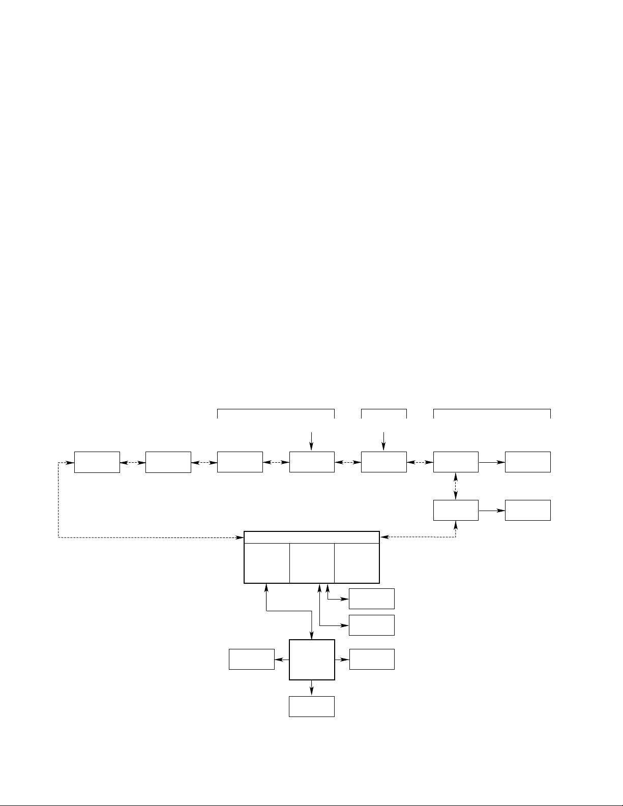
NETWORK OPERATION DURING A
FAULT CONDITION
The Eagle Quantum system utilizes a unique patented
technique for detecting problems in the communication
network wiring. This state-of-the-art feature minimizes
the possibility of a communication breakdown in the
event of a wiring fault in the communication loop and
can also serve as an aid in troubleshooting.
The communication network is constructed as a loop
that starts and ends at a pair of communication ports
located at the LCU. The nodes communicate with the
LCU over the LON/SLC as shown in Figure I-2.
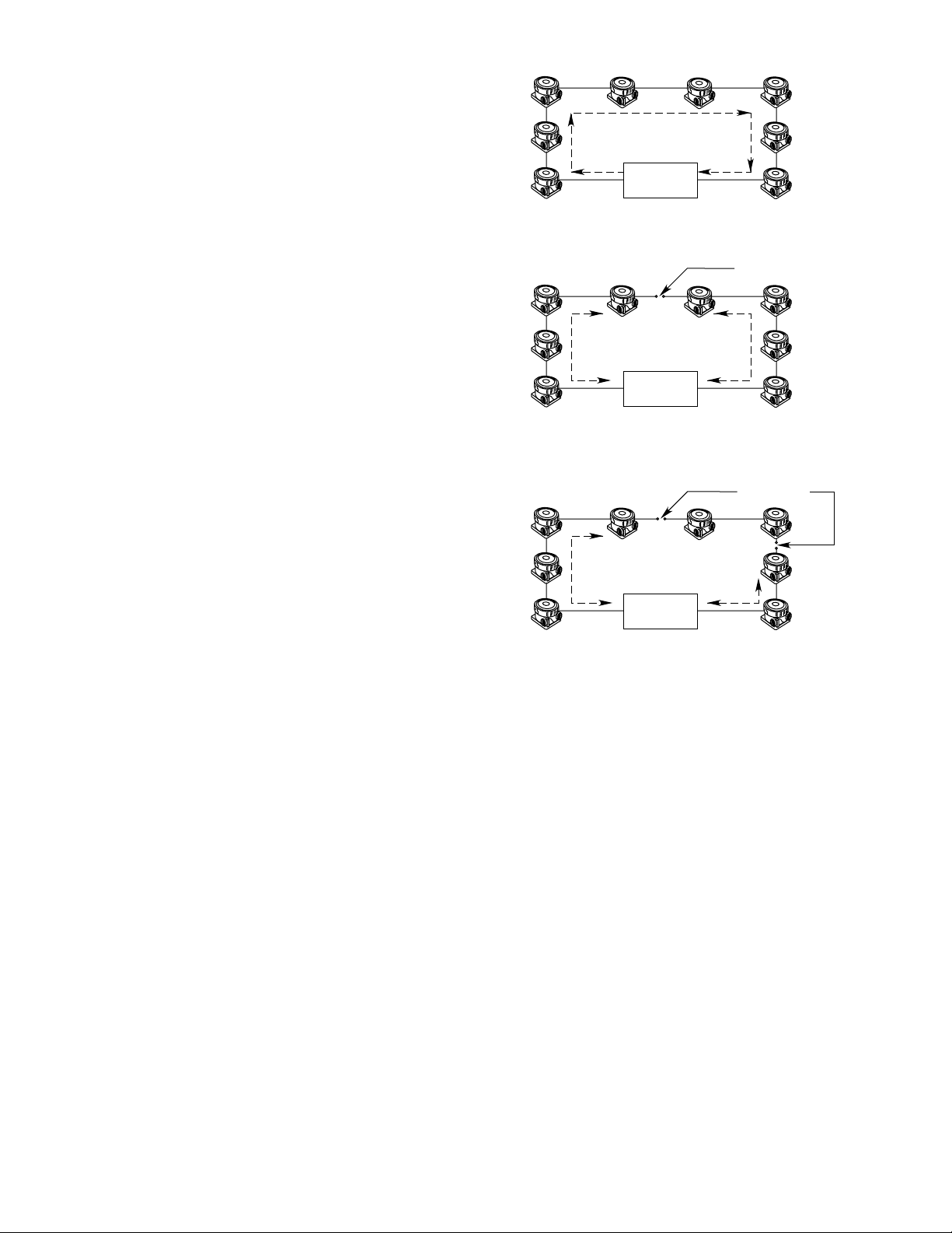
Each field device node contains both the hardware and
software necessary to isolate and re-route
communication in the event of a network wiring fault.
When a problem occurs somewhere within the network
wiring, the communication gateway located in the LCU
annunciates the fault, while the fault isolation circuitry in
the affected nodes isolates the section of the network
where the fault has occurred. Communication is
I–3 95-8470