Det-Tronics W8067S User manual

1.2
APPLICATION
The Det-Tronics W8067S Ultraviolet/Infrared (UV/IR)
Test Lamp is a portable, battery operated source of
ultraviolet and infrared radiation for periodic testing of
single frequency IR and UV/IR flame detection systems.
The test lamp produces UV and IR radiation to verify
response of the flame detection system without the
need for an open flame, and is suitable for use in non-
hazardous (de-classified) areas.
The W8067S Test Lamp can be powered by a
rechargeable, removable internal battery pack, making
it ideal for applications where detectors are mounted in
high or hard to reach locations. Alternatively, the test
lamp can be powered by the W1212 Portable Battery
Pack, which provides substantially longer operating
times between recharges. Both battery packs are
easily recharged from a 120 volt AC power source.
Internal battery pack, charger and adapter are included.
The optional W1212 portable battery pack is highly
recommended.
SPECIFICATIONS
ENCLOSURE—
Rugged, weatherproof, ABS construction.
For use in non-hazardous (de-classified) locations only.
Test lamp is not explosion-proof.
POWER SOURCE—
Cordless: Uses a rechargeable, removable battery.
Corded: Uses the W1212 portable battery pack or any
other supply with a 12 volt DC universal cigarette lighter
receptacle.
BATTERY CHARGING—
120 vac, 50/60 Hz. using adapters provided.
(220 vac adapters available. See “Ordering Information.”)
TEMPERATURE RANGE—
Operating: –15°C to +50°C (+5°F to +122°F).
Charge: 0°C to +40°C (+32°F to +104°F).
Storage: –15°C to +40°C (+5°F to +104°F).
OPERATING TIME—
Internal Battery: Up to 10 minutes continuous when fully
charged.
W1212: Offers extended operating time
between charges.
OPERATING RANGE—
The W8067S Test Lamp will activate IR and UV/IR
detectors at up to 20 feet, depending on the detector
sensitivity setting, angle of the test lamp relative to the
detector, and detector window cleanliness.
DIMENSIONS—
W8067S Test Lamp: See Figure 1.
W1212 Battery Pack: Length: 8.4 in. (21.3 cm)
Width: 2.75 in. (7.0 cm)
Height: 5.5 in. (14.0 cm).
WEIGHT (Approximate)—
W8067S Test Lamp: 13 pounds (5.9 kilograms).
W1212 Battery Pack: 11 pounds (5.0 kilograms).
1.2 ©Detector Electronics Corporation 2008 8/08 95-8626
INSTRUCTIONS
Ultraviolet/Infrared Test Lamp
W8067S
W1212 Portable Battery Pack
14.1
(35.8)
10.2
(25.9)
B2410
NOTE: APPEARANCE AND/OR
DIMENSIONS MAY VARY SLIGHTLY
Figure 1—Test Lamp Dimensions in Inches (cm)
95-86261.2 2
BATTERY CHARGING
WARNING
As with all rechargeable systems, explosive gases
could be vented from the battery on overcharge,
therefore, use the battery charger in a ventilated
area away from sources of ignition.
INTERNAL BATTERY
Charge the battery fully prior to initial use of the test
lamp. Before charging the battery, be sure that the
power switches are in the "off" position.
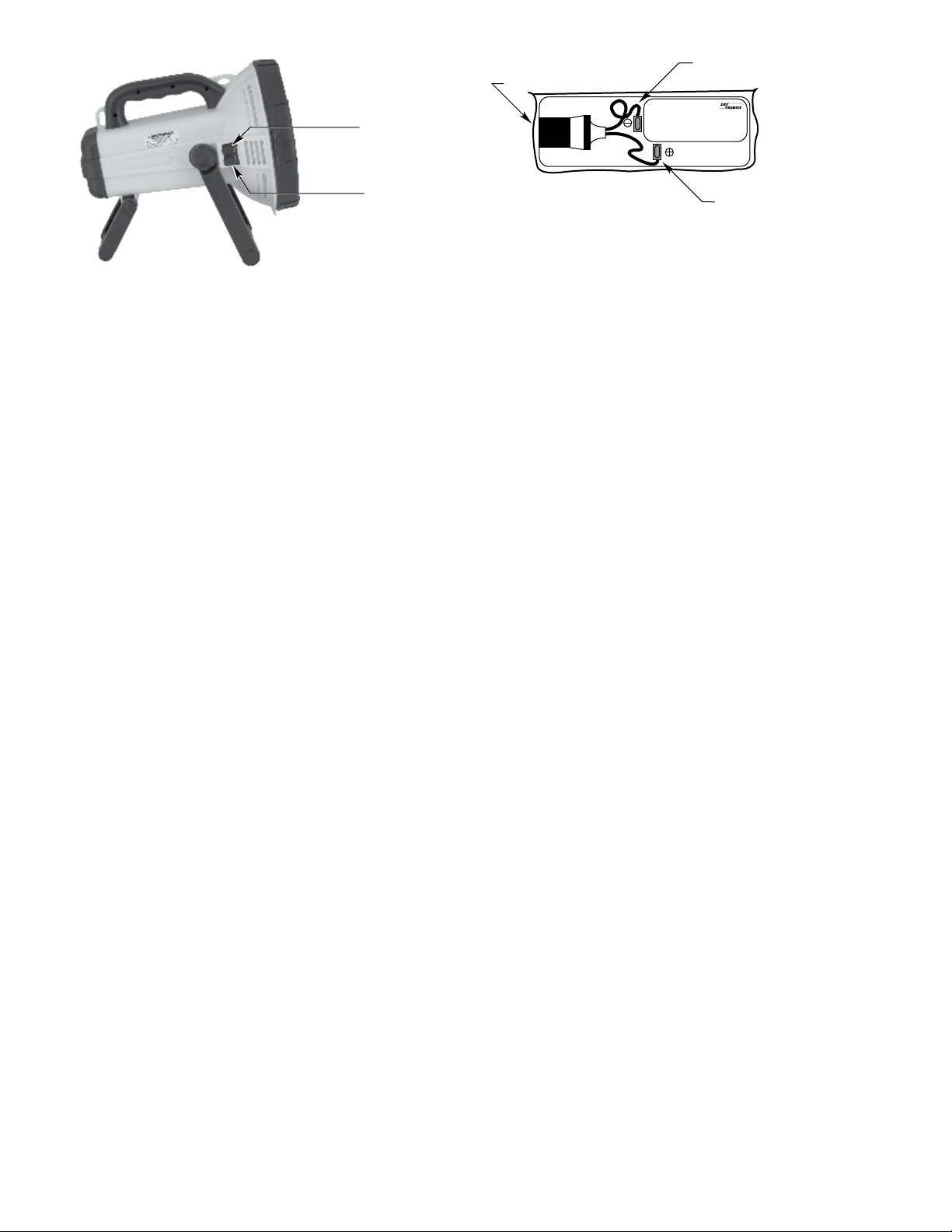
AC/DC Adapter
Plug the battery charger into the upper jack on the test
lamp (See Figure 2 for location), then plug the power
cord into a standard 120 vac outlet. The LED glows a
steady red while the unit is charging. The LED blinks
to indicate that the battery is fully charged. The time
required to fully charge the battery is approximately 15
hours.
NOTE
Do not use any charger other than the one
provided with the W8067S.
Cigarette Lighter Adapter
Plug the large end of the adapter into an external 12
Vdc power outlet and the other end into the lower jack
on the test lamp. The LED glows steady red with the
external power source connected to the test lamp.
W1212 BATTERY PACK
1. Attach the battery socket. Remove the protective
paper on the adhesive strip that is affixed to the
socket, then locate the socket on top of the battery
as shown in Figure 3 and press it firmly into place.
2. Connect the two spade connectors from the socket
to the battery terminals — small spade connector to
small battery terminal (negative) and large spade
connector to large battery terminal (positive).
3. Connect the charger to the battery socket and plug
the power cord into a standard 120 vac outlet.
4. Charge the battery for approximately 36 hours
initially and 24 hours after each complete discharge.
Do not charge for over 48 hours or damage may
result.
5. To use the W1212 with the W8067S, connect one
end of the cigarette lighter adapter to the socket
on the W1212 and the other end to the lower power
jack on the test lamp.
OPERATION
WARNING
The test lamp creates high heat. To prevent risk
of re, do not lay the test lamp face down on any
surface when it is on. Unplug the test lamp when
not in use.
WARNING
Do not look directly into the test lamp when it is
on or shine it into another person’s eyes at close
range.
GENERAL OPERATING INSTRUCTIONS
Prior to operation, charge the battery fully, following the
instructions in the “Battery Charging” section. Use the
toggle switches on the side of the lamp to turn the light
on and off. Place both switches in the "on" position.
IMPORTANT
When the test light dims, the battery charge is low.
Do not allow the battery to completely discharge.
Fully recharge the battery as soon as possible
after each use.
NEGATIVE SPADE CONNECTOR/
BATTERY TERMINAL
SOCKET
POSITIVE SPADE CONNECTOR/
BATTERY TERMINAL
W1212A1001 BATTERY PACK.
FOR USE WITH:
W8067B1001 TEST LAMP.
FOR USE IN DECLASSIFIED AREAS ONLY.
DETECTOR ELECTRONICS CORPORATION.
6901 WEST 110TH ST.
MINNEAPOLIS, MN 55438
A1721
Figure 3—W1212 Battery Pack Connections
CONNECT 120 VAC
BATTERY CHARGER HERE
CONNECT 12 VDC
CIGARETTE LIGHTER
ADAPTER HERE
B2418
Figure 2—Location of Power Terminals

1.2
DETECTOR TEST PROCEDURE
NOTE
Prior to testing, the detector viewing window
should be cleaned following the guidelines in the
detector instruction manual.
Aim the W8067S on the center viewing axis of the
detector. Refer to Figure 4. Note that any deviation
from the center line will reduce the maximum test range
as shown in Table 1. For IR or UV/IR detectors, center
the beam on the IR sensor. Then, while carefully aiming
the beam on the IR window, slightly wobble* the test
lamp just enough to induce a slight flicker effect on
the detector, but not so much that the beam no longer
covers the detector window(s). (If the test light is
momentarily removed from the detector window, the
detector’s signal processing will start over, resulting in a
longer response time.)
*NOTE
A slight wobble of the test lamp is required to
meet the “icker” requirements of the IR detection
circuitry, but is not required for the UV side of a UV/
IR detector, since UV detectors do not utilize icker
detection circuitry.
Response of the detection system will depend upon the
distance between the test lamp and the detector, the
angle of the test lamp relative to the detector, and the
sensitivity programmed into the detection system. It
may be necessary to decrease the distance between
the detector and the test lamp in order to obtain a
response. Typical response time is 5 to 15 seconds.
NOTE
The maximum recommended battery charge level
is required for maximum test range capability.
SERVICE PROCEDURES
BATTERY MAINTENANCE
The battery must be charged and stored properly to
ensure satisfactory performance. Always store the
battery in a fully charged condition. Disconnect the
charger from the battery. Store in a cool place.
Internal Battery. Charge the battery for at least 15
hours and never over 24 hours — initially and
immediately after each discharge. Never leave the
battery discharged. Recharge at least every 3 months.
Internal Battery Replacement. Care should be taken
when releasing the spade connectors, we strongly
suggest refraining from pulling on the wires as a
method of removal. Refer to Figure 5 for recommended
removal.
W1212 Battery. Charge for 36 hours initially and for
24 hours after each discharge. Recharge for 24 hours
every eight weeks when not in use.
TROUBLESHOOTING
If the test lamp fails to light:
– Check battery charge.
– Check battery connections if using W1212.
– Check internal battery for correct installation.
If the battery fails to charge, check:
– Charger connections.
– Input power to charger.
– Charger should be warm when plugged in. If not,
replace the charger.
– If all above checks out, replace the battery.
If the battery has been charged and the test light
becomes dim within the first 30 seconds, the battery
must be replaced.
395-8626
BEAM CENTER
A2411
UV
IR
Figure 4—Recommended Test Lamp Position
DEVIATION FROM PERCENTAGE OF
CENTER LINE MAXIMUM RANGE
0° 100%
15° 80%
30° 50%
45° 25%
Table 1—Detector Response to W8067S at Various Angles
Relative to Center Line
A2444
PUSH DOWN ON THE TINY LEVER,
THEN PULL FOR EASY RELEASE OF
THE SPADE CONNECTORS
NOTE: PRIOR TO
REMOVING THE OLD
BATTERIES, BE SURE
TO T AKE NOTE OF
THE WIRING
Figure 5—Spade Connector Removal on Internal Battery for W8067S
95-86261.2
BULB REPLACEMENT
WARNING
Always allow the test lamp to cool before replacing
the bulb.
When replacing the bulb, use only part number
103853-001, available from Detector Electronics. Use of
other bulbs can adversely affect the performance of the
test lamp.
1. Disconnect any power cords attached to the test
lamp.
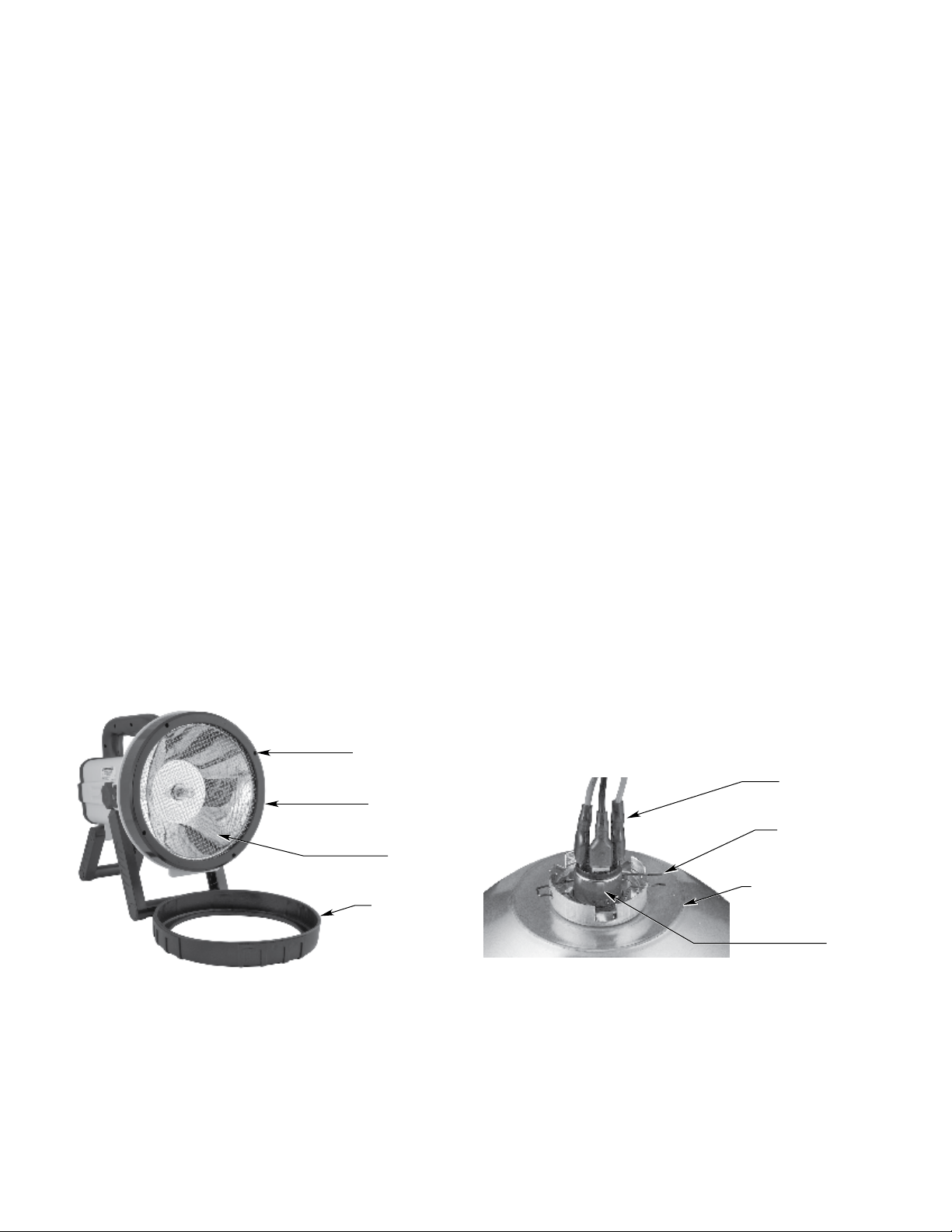
2. Pull the rubber cover off the front of the test lamp.
See Figure 6.
3. Remove the Phillips screws from the reflector cap.
4. Remove the reflector. Use care not to damage the
wiring or connections.
CAUTION
Do not touch the glass bulb or the inside of
the reflector. Perspiration and oil from fingers
can adversely affect the performance of the
bulb. Handle the bulb by its metal base only. If
necessary, the bulb can be cleaned with alcohol.
5. Open the bulb retainer to release the bulb. (Push
the wire prongs together and pull up to release
bulb.) See Figure 7.
IMPORTANT
Note the location of each of the three bulb wires.
The wires must be connected to the new bulb in
the same way to ensure proper operation of the
lamp switches.
6. Disconnect the bulb wire connections from the old
bulb and install them on the new bulb.
7. Holding the new bulb by its base, install it in the
reflector.
8. Replace the wire bulb retainer.
9. Place the reflector inside the lamp housing.
10. Secure the reflector cap to the lamp housing using
the screws that were removed earlier. Use care not
to over-tighten.
11. Re-install the rubber cover.
ORDERING INFORMATION
When ordering, specify:
Description Number
Model W8067S1003 Test Lamp 006439-004
Model W1212 Portable Battery Pack 006438-001
Optional 220 vac ac/dc adapter (Euro) 103852-001
Bulb 103853-001
Internal Battery, 6V
(2 required for 12V Operation)
103855-001
Detector Electronics Corporation
6901 West 110th Street • Minneapolis, Minnesota 55438 • Operator (952) 941-5665 or (800) 765-FIRE
Customer Service (952) 946-6491 • Fax (952) 829-8750 • www.det-tronics.com • E-mail: [email protected]
RUBBER COVER
PHILLIPS SCREW (4)
REFLECTOR CAP
REFLECTOR
B2420
Figure 6—Front of Test Lamp with Rubber Cover Removed
BULB RETAINER
BULB
BACK OF REFLECTOR
BULB WIRES (3)
A2421
Figure 7—Bulb Removal
This manual suits for next models
1
Table of contents


