5
AC/DC Current Measurements
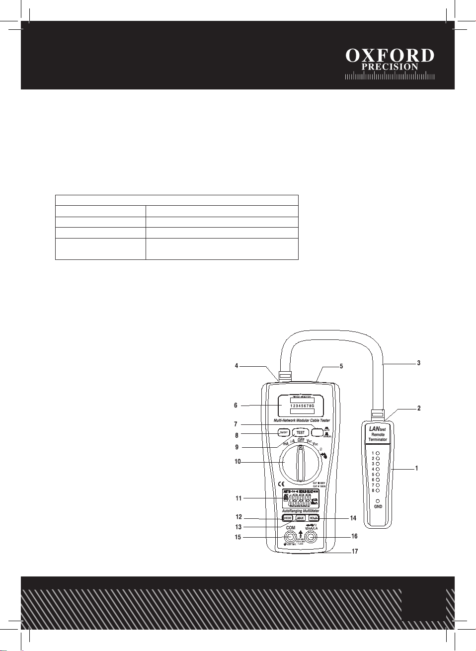
1. Set the function switch to the µA/mA position.
2. Insert the black test lead into the negative COM terminal and the red test lead into the
positive µA/mA terminal.
3. For current measurements up to 2000µA DC/AC, set the function switch to the mA position
4. Press the MODE button to indicate “DC” / “AC” on the display.
5. Remove power from the circuit under test, then open up the circuit at the point where
you wish to measure current.
6. Touch the black test probe tip to the negative side of the circuit.
Touch the red test probe tip to the positive side of the circuit.
7. Apply power to the circuit.
8. Read the current in the display
Resistance Measurement
WARNING: To avoid electric shock, disconnect power to the unit under test and discharge all
capacitors before taking any resistance measurements. Remove the batteries and unplug the
power leads.
1. Set the function switch to the Ωposition.
2. Insert the black test lead into the negative COM terminal and the red test lead into the
positive Ωterminal.
3. Touch the test probe tips across the circuit or part under test. It is best to disconnect one side
of the part under test so the rest of the circuit will not interfere with the resistance reading.
4. Read the resistance in the display.
Continuity Check
WARNING: To avoid electric shock, never measure continuity on circuits or wires that have
voltage on them.
1. Set the function switch to the
Touch the red test probe tip to the positive side of the
circuit.
7. Apply power to the circuit.
8. Read the current in the display
RESISTANCE MEASUREMENT
WARNING: To avoid electric shock, disconnect power to
the unit under test and discharge all capacitors before
taking any resistance measurements. Remove the
batteries and unplug the line cords.
1. Set the function switch to the Ωposition.
2. Insert the black test lead into the negative COM terminal
and the red test lead into the positive Ω terminal.
3. Touch the test probe tips across the circuit or part under
test. It is best to disconnect one side of the part under
test so the rest of the circuit will not interfere with the
resistance reading.
4. Read the resistance in the display.
CONTINUITY CHECK
WARNING: To avoid electric shock, never measure
continuity on circuits or wires that have voltage on them.
1. Set the function switch to the position.
2. Insert the black test lead into the negative COM terminal
and the red test lead into the positive Ω terminal.
3. Press the MODE button to indicate on the
display
4. Touch the test probe tips to the circuit or wire you wish to
check.
position.
2. Insert the black test lead into the negative COM terminal and the red test lead into the
positive Ωterminal.
3. Press the MODE button to indicate
Touch the red test probe tip to the positive side of the
circuit.
7. Apply power to the circuit.
8. Read the current in the display
RESISTANCE MEASUREMENT
WARNING: To avoid electric shock, disconnect power to
the unit under test and discharge all capacitors before
taking any resistance measurements. Remove the
batteries and unplug the line cords.
1. Set the function switch to the Ωposition.
2. Insert the black test lead into the negative COM terminal
and the red test lead into the positive Ω terminal.
3. Touch the test probe tips across the circuit or part under
test. It is best to disconnect one side of the part under
test so the rest of the circuit will not interfere with the
resistance reading.
4. Read the resistance in the display.
CONTINUITY CHECK
WARNING: To avoid electric shock, never measure
continuity on circuits or wires that have voltage on them.
1. Set the function switch to the position.
2. Insert the black test lead into the negative COM terminal
and the red test lead into the positive Ω terminal.
3. Press the MODE button to indicate on the
display
4. Touch the test probe tips to the circuit or wire you wish to
check.
on the display
4. Touch the test probe tips to the circuit or wire you wish to check.
5. If the resistance is less than approximately 150Ω, the audible signal will sound. If the circuit
is open, the display will indicate “OL”.
Diode Test
1. Set the function switch to the
Touch the red test probe tip to the positive side of the
circuit.
7. Apply power to the circuit.
8. Read the current in the display
RESISTANCE MEASUREMENT
WARNING: To avoid electric shock, disconnect power to
the unit under test and discharge all capacitors before
taking any resistance measurements. Remove the
batteries and unplug the line cords.
1. Set the function switch to the Ωposition.
2. Insert the black test lead into the negative COM terminal
and the red test lead into the positive Ω terminal.
3. Touch the test probe tips across the circuit or part under
test. It is best to disconnect one side of the part under
test so the rest of the circuit will not interfere with the
resistance reading.
4. Read the resistance in the display.
CONTINUITY CHECK
WARNING: To avoid electric shock, never measure
continuity on circuits or wires that have voltage on them.
1. Set the function switch to the position.
2. Insert the black test lead into the negative COM terminal
and the red test lead into the positive Ω terminal.
3. Press the MODE button to indicate on the
display
4. Touch the test probe tips to the circuit or wire you wish to
check.
position.
2. Press the MODE button to indicate
Touch the red test probe tip to the positive side of the
circuit.
7. Apply power to the circuit.
8. Read the current in the display
RESISTANCE MEASUREMENT
WARNING: To avoid electric shock, disconnect power to
the unit under test and discharge all capacitors before
taking any resistance measurements. Remove the
batteries and unplug the line cords.
1. Set the function switch to the Ωposition.
2. Insert the black test lead into the negative COM terminal
and the red test lead into the positive Ω terminal.
3. Touch the test probe tips across the circuit or part under
test. It is best to disconnect one side of the part under
test so the rest of the circuit will not interfere with the
resistance reading.
4. Read the resistance in the display.
CONTINUITY CHECK
WARNING: To avoid electric shock, never measure
continuity on circuits or wires that have voltage on them.
1. Set the function switch to the position.
2. Insert the black test lead into the negative COM terminal
and the red test lead into the positive Ω terminal.
3. Press the MODE button to indicate on the
display
4. Touch the test probe tips to the circuit or wire you wish to
check.
on the display. Touch the test probes to the diode
under test.
MAX button
To hold the highest reading on the LCD:
1. Press the MAX button. The meter reading will not change as readings change.
2. Press the MAX button again to return to normal operation.
Hold Button
The Hold function allows the Multimeter to “freeze” a measurement for later reference
1. Press the “HOLD” button to “freeze” the display, the “HOLD” indicator will appear.
2. Press the “HOLD” button to return to normal operation.