Uson Qualipak-770 User manual

DocumentNo.770013Rev.2.0
Leak Test System

Portionsofthesoftwarearecopyright©2012Uson,L.P.and
copyright©1991FreeSoftwareFoundation,Inc.
59TemplePlace,Suite330,Boston,MA02111‐1307,USA
Productortradenamesmentionedinthismanualmaybetrademarksorregisteredtrademarksoftheir
respectivecompanies.
Usonreservestherighttomodifyorotherwisechangespecificationsand/ortesterperformancewithout
notice.Usonhasmadeeveryattempttocompletelydescribetheoperationofthetester.Usonshallnot
beliablefortechnicaloreditorialerrorsoromissions.
Thismanualcopyright©2021UsonL.P.
Allrightsreserved.PrintedintheU.S.A.
PublishedbyUsonL.P.
8640NorthEldridgeParkway
Houston,Texas77041
U.S.A.
(281)671‐2000
(281)671‐2001Fax
Mail:[email protected]
www.uson.com
CustomerSupportHotline:281‐671‐2222

1
TableofContents
Section1:Safety......................................................................................................................2
SafetyPrecautions(English).............................................................................................................2
SafetyPrecautions(Español)............................................................................................................3
Section2:Introduction............................................................................................................4
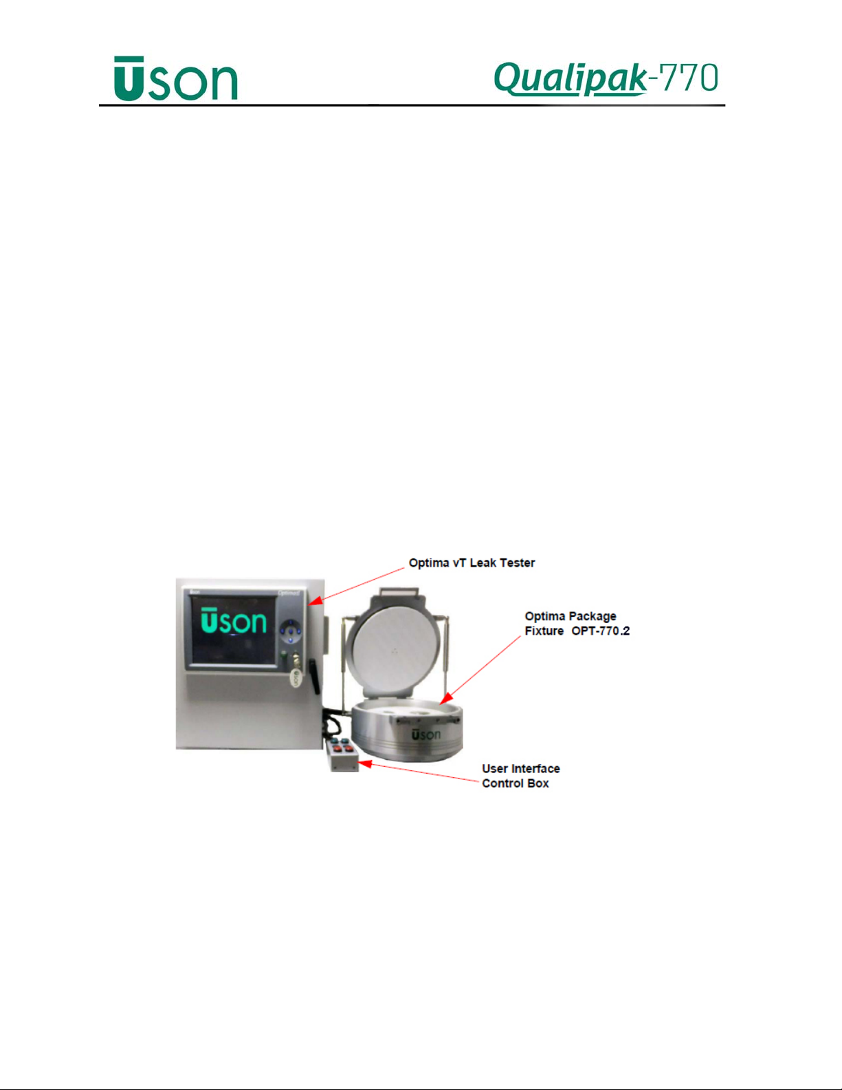
Overview.........................................................................................................................................4
Specifications...................................................................................................................................5
HowitWorks...................................................................................................................................5
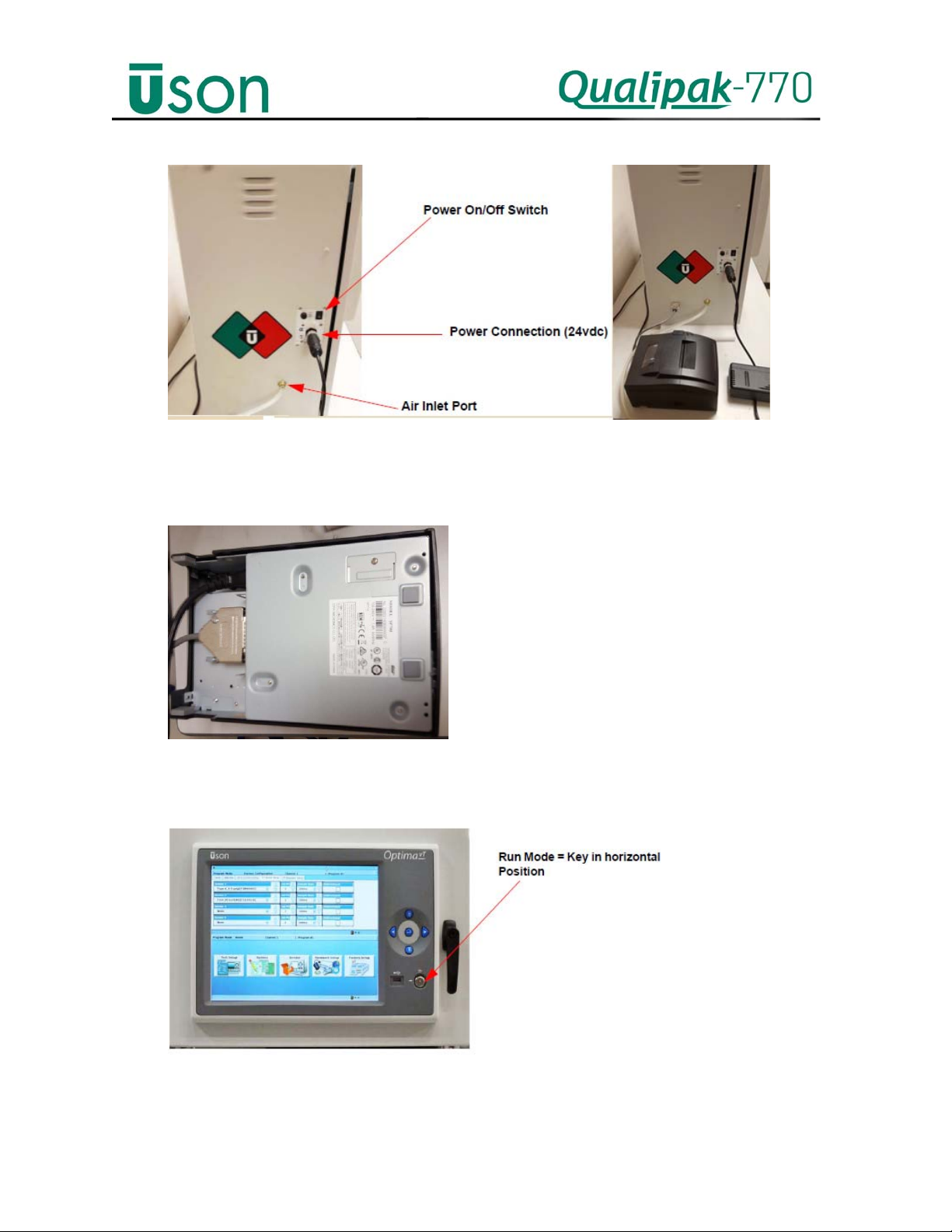
GettingStarted................................................................................................................................6
SystemTest/ChamberSealTest.......................................................................................................9
Section3:Operation..............................................................................................................11
TestingPrinciple.............................................................................................................................11
Testing...........................................................................................................................................12
Pre‐ProgrammedTests......................................................................................................................................13
ProgrammingaNewTest....................................................................................................................................14
SetupScreen...................................................................................................................................................14
SensorsTab.....................................................................................................................................................16
OutputsTab
.....................................................................................................................................................17
StepLimitsTab
................................................................................................................................................18
JumpsTab
........................................................................................................................................................18
DownloadtoTCU............................................................................................................................................19
ChallengeTest.....................................................................................................................................................20
Lidadjustment...............................................................................................................................22
Section4:Maintenance.........................................................................................................24
RoutineMaintenance.....................................................................................................................24
Daily....................................................................................................................................................................24
Weekly................................................................................................................................................................24
SixMonths..........................................................................................................................................................24
Annually..............................................................................................................................................................24
Cleaning..............................................................................................................................................................25
UserchangeableSpareparts..........................................................................................................25

2
Section 1: Safety
Safety Precautions (English)
WARNING: Areas of the equipment and/or manual that display this
symbol, or variation of, are potentially hazardous. Consult the
appropriate section of the user manual in respect of the specific
hazard.
WARNINGS: The system operates on 24VDC from a power supply
(supplied by Uson or customer), which must be connected to an
earthed (grounded) power supply of 100-240VAC 50/60Hz.
The covers on the equipment should be removed only by personnel
trained to avoid the risk of electric shock. The power supply to the
equipment must be switched off and disconnected before removing
any covers.
Do not substitute the fuse rating. Always use the correctly rated fuse,
failure to do so may be hazardous and can cause damage to the
equipment.
Do not make or break external connectors or connections while the
Optima vT is switched on.
The component to be tested, and the air supply line to the Optima vT
must be free from water or liquid residue before testing; otherwise,
damage may be inflicted on the sensitive transducer within the
instrument.
Operation of this product outside of the manufacturer's instructions
may impair the protection provided by the equipment.
This instrument is capable of supplying high-pressure air. Before
commencing any component tests, ensure that the system is guarded
to local health and safety standards.

3
Safety Precautions (Español)
WARNING/ADVERTENCIA
Las zonas del equipo que muestran este sRmbolo son potencialmente
peligrosas. Consulte la sección del manual del usuario
correspondiente a ese peligro en particular.
System funciona con 24VDC desde una fuente de alimentación
(suministrado por Usón o cliente), que debe estar conectado a una
fuente de alimentación conectada a tierra (masa) de 100-240VAC
50/60Hz.
No cambie el voltaje del fusible. Utilice siempre el voltaje correcto del
fusible, si no lo hiciera podrRa daZar el Optima vT.
No realice o rompa conexiones o conectores externos mientras esté
encendido el Optima vT.
Cuando utilice un acoplamiento neumático con el Optima vT tenga
cuidado de asegurarse de que tanto el acoplamiento como el
componente estén correctamente empotrados.
Debe comprobar el componente y la línea de suministro de aire al
Optima vT debe estar libre de agua o cualquier residuo líquido antes
de la comprobación; si no fuera así podría daZar el transconductor,
altamente sensible, que se encuentra en el interior del instrumento.
El falta de cumplimiento de las instrucciones de uso indicadas por el
fabricante para este producto, puede perjudicar la protección provista
en el equipo.
El instrumento es capaz de suministrar aire a alta presión. Antes de
empezar prueba alguna de cualquier componente asegurarse de que el
sistema cumple las normas establecidas por las autoridades locales
en materia de Seguridad e Higiene.

4
Section 2: Introduction
Overview
The Qualipak-770 is an easy-to-use leak testing fixture used with Uson’s Optima vT Leak
Tester to perform seal integrity and leak testing on packages/parts for the food, medical,
and pharmaceutical industries. See Figure 1.
The Qualipak-770 Packaging Test System instructions are outlined in two manuals:
• Qualipak-770 owner’s guide
• Optima vT’s owner’s guide (document# 660012)
You will need to reference both manuals for configuring and operating the system.
Figure 1: Qualipak-770 Packaging Test System

5
Specifications
Air supply: 6 bar
Mains supply: 100v -240v
Weight: Chamber Packed 40 kg, unpacked 35 kg/Optima Packed 42 kg, unpacked 32 kg
Chamber, lid and internal components Anodised Aluminium.
Adjustment lock nut Black acetyl
Hinges and all Screws Stainless Steel
Latch and Striker plate Hardened Stainless Steel
Pressure plate sheet: Porvair
Sample Infills Polypropylene
Lid seal Silicone
O-rings Nitrile
How it Works
The Qualipak-770 Package Test Fixture is designed to integrate with the Optima vT Leak
Tester to test the integrity of air tight packages/parts by performing a Vacuum Force Decay
test on the various packages/parts. The test part is loaded into the test fixture. The
operator selects the appropriate program for the part to be tested, then selects the start
button on the test fixture; the test automatically starts. During the test, the part under test
is subjected to a vacuum supplied by the Uson Leak Tester. The vacuum level is regulated
by the Optima Leak Tester, and during the test, the Qualipak-770 feeds back a signal
from a load cell to the Uson Leak Tester. The Leak Tester program then differentiates
between a good and bad part.

6
Getting Started
Note: Conduit can be threaded through either side of the test
chamber.
Perform the following steps to get your system ready to use:
1. Unpack the Optima Package Test Fixture and the Optima vT Leak Tester.
2. Turn the QUALIPAK-770 upside-down and place on a sturdy workbench. Then
remove the fixture’s bracket by unscrewing its 2 screws. See Figures 2 & 3.
3. Connect the vacuum connector to the vacuum connector inlet. See Figures 2 & 3.
4. Load cell plugs left and right. See Figures 2 & 3.
5. Reassemble bracket.
Figure 2: Package Tester Connections

7
Figure 3:Package Tester Connections Completed
6. Turn the fixture upright, and then remove the two transit screws. See Figure 4.
Figure 4: Transit Screws
7. Connect power supply to the Optima vT’s 24vdc input. See Figure 5.
The systems power supply must be connected to an
earthed (grounded) power supply of 90 - 260V, 50 - 60Hz. Only
personnel trained to avoid the risk of electric shock should remove
the covers on the equipment. The power supply to the equipment
must be switched off and disconnected before removing any covers.
Do not make or break external connectors or connections while the
system is switched on.
8. Connect the positive pressure to the Optima vT’s air inlet port (optional)
See Figure 5.
9. Connect serial communication and power cables to the printer (optional).
See Figure 6.
10. Connect main inlet to power supply unit. See Figure 5.
11. Turn the Optima vT power On. See Figure 5.
12. Connect specified air supply, then turn air On to the system. Unit will go
through a boot-up sequence.

8
Figure 5: P: Optima vT Power/Air Connections - Side View
13. Connect serial communication and power cables to the printer (optional).
See Figure 6.
Figure 6:Serial Communications
14. Switch the program/run key to run (key in horizontal position). See Figure 7.
Figure 7: Optima vT Interface Mode Key

9
System Test/Chamber Seal Test
Follow these steps to perform a system test/chamber seal test:
1. On the Optima vT, enter the dashboard screen by selecting Run Mode Dashboard
(refer to Optima vT manual). See Figure 8.
2. Select Program 112 (chamber seal test) from drop down menu.
Figure 8: Dashboard Screen
3. Start the Chamber Seal Test program, and then adjust internal regulator until Gauge
(Ch1) 2G reads 3 bar, and Optima display sensor X1 =~-500mbar. Once pressure is
achieved, press Stop. See Figure 9.
Figure 9: Optima vT Internal Controls

10
4. Run test to ensure system integrity. Press Start button (if the start button is not on
the dashboard, use start on remote box). Allow test cycle to complete its 5 steps: Fill,
Isolate, Stabilize, test and Exhaust (see Figure 10). The result of this test should be
less than 0.3 mbar. The Optima vT will give a pass if within the tolerance.
See Figure 11.
Figure 10: Optima vT: Chamber Seal Test Run Screen
Figure 11: Optima vT: Chamber Seal Test Results Screen

11
Section 3: Operation
Testing Principle
The Optima Q770 is based on the same test principle as the early Q700 range for flexible
package testing. However, the parameters are now unrestricted, and can be programmed
to suit your specific application.
The test principle is a vacuum is applied to the chamber, which encourages the
pack to inflate. The package inflates until the control pressure is achieved; this
creates a force onto the load cells. Once the control vacuum has been reached, the
chamber is isolated and a period of time is allowed for the package to stabilise.
Then the force is monitored for a decay. If a package decays at a rate greater than
expected, it’s assumed to have a leak, failure (red light). If the force does not
decay, then the package is assumed to be good /pass (green light).
Results can either be logged to USB or to a Printer, using the pre-written format, or can
be edited to meet individual needs.

12
Testing
To Perform a Test:
1. Select correct program for package to be tested from. See “Pre-programmed Tests”
later in this section.
2. Insert package into cavity, ensuring the pack is central and is not hanging over the
cavity. Ensure pack is not folded. See Figure 12.
Figure 12: Package Testing: Insert package
3. Close lid and press either of the green start buttons (either from Optima vT
screen or control box). If lid needs adjusting, please see “Lid Adjustment” later
in this section. See Figure 13.
Figure 13: Package Testing: Lid Closed
4. The test will continue through the exhaust phase. If both packs pass, the green pass
light illuminates on both sides. If only one pack passes, the green light associated
with the side which passed illuminates. Similarly, if both packs fail, the red reject
light illuminates on both sides. If only one pack fails, the red light associated with the
side which failed illuminates. See Figure 14.

13
Figure 14: Package Testing: Pass Results
5. Results will be outputted to USB (if selected). Remove packs and resume to next test.
Pre- Programmed Tests
The Optima vT Package system contains several pre-programed tests:
• Program 1: Example program.
• Program 2: Any specifically ordered program based on samples received.
• Program 3 - 89: Free for customer designed programs unless requested for
pre-programmed tests.
• Program 90: Master program, which can be cloned to another position for
editing into a new position or for a different product.
• Programs 101, 102, 103: Designated for calibration of the sensors; cannot be
seen in run mode. Recommended calibration only be performed by Uson
trained engineers; errors could seriously affect results integrity.
• Program 109: Lid adjust. See “Lid Adjustment” later in this Section.
• Programs 110 and 111: Challenge tests left and right. See “Challenge Test”
later in this Section.
• Program 112: Chamber seal test. See “Chamber Seal Test” earlier in this
document.

14
Programming a New Test
The Optima has a pre-configured test for a basis to create new tests from. This is
programed into position 90 and is called “Master Program”.
It is recommended to clone program 90 into a new position before editing.
To do this:
1. Turn the key on the Optima vT to the program position (vertical position).
2. Open the Test Setup screen.
3. Select the first tab “Test”. Select Clone. Once cloned, select the cloned
program from the menu. See Figure 15.
Figure 15: Clone Screen
Setup Screen
Select the Step tab to enter the Step screen, as shown in Figure 16. For each test, the
following parameters are recommended for programming a new test. In addition, select
the step type and duration. Reference the Optima vT’s Owner’s guide for additional
information on setting up a new test.
Figure 16: Setup Screen

15
Auto zero pressure: Zeros the pressure sensor before the test start, taking away any
ambient pressure changes, which may affect the test. The pre-set limits are -68 to +68. If
the instrument starts failing during this process, there may be a fault in the system, which
requires checking.
Auto zero left force sensor: Tares the left force sensor, which removes the effect of any
minor changes in pack weight or infill variances. The pre-set limits are -99 to 9999. if the
instrument starts failing during this process, there may be a fault in the system, which
requires checking.
Auto zero right force sensor: Described in “Auto zero left force sensor”.
Fill: Evacuates the chamber of air to a controlled pre-set limit; allows the positive
pressure inside the pack to inflate the pack, creating the force onto the load cell,
and a pressure differential between the inside of the pack and its outside. The
lower the pre-set pressure, the greater pressure differential is inside and outside the
pack. Depending on the pack’s construction, a large pressure difference can cause
the pack to burst/split/open.
Fill 2 left gross: Measures the force applied to the load cell to ensure it’s
sufficient. A pack with a large hole or altogether missing will not inflate to create a
force, or inflate enough to create force to reach the minimum limit of the test. The
limit is determined by knowledge the normal force created by a known good pack
onto the load cell, and then setting the limit (gross) below the lowest recorded
known good pack. Creating a pack with a known gross leak can test to confirm the
parameters are set.
Fill 3 right gross: Described for “fill 3 left gross”.
Isolate: A half-second step to allow time for valves to operate before proceeding.
Stabilize: Allows the pack to settle into its inflated position. The packs don’t
inflate uniformly. While the pack is stabilizing, the force on the load cell will vary as it
settles into the inflated shape. If the stabilization step is too short, it could lead to false
failures of good packs.
Stabilize measure left force: Once the stabilization period is over, the force on the
load cell is measured to ensure the force has been maintained during the
stabilization step. A pack with a hole smaller than a gross but greater than a fine
leak, could drop below the gross limit during stabilization, therefore, if after
stabilization the force is not great enough, then the pack will be read as a reject.
The limit should be the same as the gross leak test (fill step measure).

16
Stabilize measure right force: Described for “Stabilize measure 2”.
Measure left: Measures the difference in force between the start of the measure step and
the end of the measure step. If the force decay is larger than the limit, the pack will be
read as a reject. If the force decay is less than the limit, then the pack is read as a pass.
The limit should be the maximum limit the pack is allowed to decay over the test time.
This is normally worked out by testing packs with known leaks and setting the limits
around the results
Measure right: Described for “measure left”. Result: Displays the final results.
Exhaust: Vents the chamber back to atmospheric pressure. The lid cannot be opened
until the exhaust step has been completed.
Sensors Tab
Select the Sensors Tab (Figure 17) to enter the Sensors screen. On the sensors screen,
select the primary sensor (P-S), which is the sensor you want to look at during this test.
Select the units you wish to measure each step in.
Figure 17: Sensors Tab

17
Outputs Tab
Select the Outputs Tab (Figure 18) to enter the Outputs screen. This screen is used to
select outputs to the valves and LEDs required for each step. S-CMD are used for
turning on/off valves. Acc/Rej are assigned outputs to turn on for corresponding
accept/reject results. See Figure 19.
Figure 18: Outputs Tab
Figure 19: Outputs Screen

18
Step Limits Tab
Select the Step limits tab (Figure 20) to enter the Step Limits screen. Step limits are
parameters/logic each step must fall within to pass or fail a step. If the step logic is not
achieved, a fail/reject is given before moving to the next step.
Each step must have a sensor selected to examine for a pass/fail.
Figure 20: Step Limits Screen
Jumps Tab
Select the Jumps tab (Figure 21) to enter the jump screen. The jump screen is used to
configure which step or program the test will jump to based on the result condition of the
step (accept or reject).
Figure 21: Jumps Screen
Table of contents
Other Uson Test Equipment manuals
Popular Test Equipment manuals by other brands

Chauvin Arnoux
Chauvin Arnoux PAC 12 user manual

Tegam
Tegam 2510A Instruction and service manual

ALAT UJI
ALAT UJI PTT 2000 operating instructions

Fluke
Fluke FIBER QUICKMAP Getting started guide

VOLTCRAFT
VOLTCRAFT DSO-4062A operating instructions

Teledyne Lecroy
Teledyne Lecroy WaveSurfer 3024Z Operator's manual