Detectors Incorporated D390 User manual

MAN‐D390‐0001
1
INSTRUCTION MANUAL
Detectors Incorporated
Model D390
Flame Detector

MAN‐D390‐0001
2
TableofContents
INTRODUCTION……………………………………………………………… 3
Productdescription…………………………………………………………. 3
Specifications………………………………………………………............. 4
General……………………………………………………………………………. 4
Electrical………………………………………………………………………….. 4
Environmental…………………………………………………………………. 4
Mechanical………………………………………………………………………. 4
INSTALLATION…………………………………………………………………. 5
DetectorDimensions……………………………………………………….. 5
MountingtheDetector……………………………………………………. 5
Positioning………………………………………………………………………. 5
DirectMounting………………………………………………………………. 5
InstallationTips……………………………………………………………….. 5
DetectorConfiguration……………………………………………………. 6
DetectorWiring……………………………………………………………….6‐11
OPERATIONANDSTARTUP……………………………………………… 12
DetectorPerformanceandResponse………………………………. 12
DetectorOperation………………………………………………………….. 12
DetectorVisualStatusIndication……………………………………… 12
NormalOperation……………………………………………………………. 12
ALARMOperation…………………………………………………………….12‐13
FaultOperation……………………………………………………………….. 13
DetectorSelf‐Test……………………………………………………………. 14
DetectorOpticalPathTest………………………………………………. 14
MAINTAINANCE………………………………………………………………. 14
InspectionandCleaning…………………………………………………… 14
PeriodicTesting……………………………………………………………….. 14
TROUBLESHOOTING……………………………………………….. 15
EVENTLOG……………………………………………………………… 15
ACCESSORIES………………………………………………………….. 15
PRODUCTSUPPORT……………………………………………….. 15
TechnicalSupportandCustomerSupport………………. 15
WARRANTY……………………………………………………………. 16
APPENDIX“A”
ORDERINGINFORMATION…………………………………….. 17
APPENDIX“B”………………………………………………………… 18

MAN‐D390‐0001
3
1.0 Introduction
1.1 ProductDescription
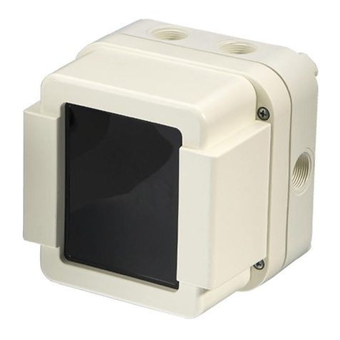
The Multi‐Spectrum D390 is a stand‐alone 3IR flame detector designed
specificallyforinstallationinSemiconductorcleanroomsandwetbenches
forfastdetectionofHydrocarbonandNon‐Hydrocarbonbasedfires.The
ModelD390sensestheIRradiationin3discretebandsofInfraredinthe
rangeof2‐5microns.
The Model D390 sensors and electronic circuit boards are enclosed in a
sealedwater‐tightPolypropyleneenclosureratedIP67makingitanideal
detectorforinstallinginharshchemicalladenenvironment.Thedetector
canbeusedasastand‐alonedeviceorcanbeinterfacedwithanyapproved
firealarmpanel.Thedetectorwillrespondtoonesquare‐footn‐Heptane
firewithin3‐5secondsfromof30feet.

MAN‐D390‐0001
4
1.2 Specifications
1.2.1 General
Field‐of‐View: 90°Horizontal&Vertical
SpectralSensitivity: IR: 2‐5microns(3discretebands)
ResponseTime: 3‐5Seconds
DetectionRange: 1’x1’n‐Heptanefire:30feet
32”Hydrogenplume(3/8”orifice):20feet
1.2.2 Electrical
OperatingVoltage: 24VDCnominal(18‐31),Regulated
PowerConsumption: Standby:60mA@24VDC
Alarm:90mA@24VDC
RelaysOutputs: Alarm&AuxiliaryRelays:
SPDT—contactsrated2A@24VDC
De‐EnergizedwithN.O.contacts(powerapplied)
Faultrelay:
SPST–contactrated2A@24VDC
EnergizedwithClosedcontact(powerapplied)
AnalogOutput: 0‐20mAStepped‐Source
Communication: RS485ModBus
VisualIndications: GreenLED‐Normal
RedLED‐Alarm
AmberLED‐Fault
Wiring Integralmulti‐conductorcableharness
withTeflonJacket
20AWG15‐conductorcable,20’long
1.2.3 Environmental
HumidityRange: 5to95%relativehumidity,non‐Condensing
TemperatureRange: ‐40to+185°F(‐40to+85°C)
EnclosureType: NEMA4,IP67
1.2.4 Mechanical
EnclosureMaterial: Polypropylene,sealed
Weight: 1.5lbs.(0.7kg)

MAN‐D390‐0001
5
2.0 Installation
2.1 DetectorDimensions
TheD390detectorhas(4)6mmholesintherearmountingflange(Figure1)thatcanbeusedtomount
thedetectordirectlyonaflatsurface.Thedetectorcanalsobemountedusinganoptional
Polypropyleneswivelmountingbracket(Figure2)thatallowsthedetectoradjustmentinverticalaxis.
Figure1–DetectorDimensions
2.2 MountingtheDetector
2.2.1 Positioning‐Thedetectorshouldbeinstalledsuchthatthecenterofthedetector’sfield‐of‐view
isaimeddirectlyatthecenteroftheareatobeprotected(hazardarea).Detectorsshouldbe
installedabovethehazardareapointingdownwardwithnoobstructionoftheField‐of‐View.
2.2.2 DirectMounting.‐Thedetectormayalsobemounteddirectlytoaflatsurfaceusingthe(4)
mountingholeontherearmountingflangeandsecureitfirmlywith(4)stainlesssteelscrews.
2.2.3 InstallationTips:‐Wheninstallingthedetectors,beawareofthefollowingconditions:
a) Ifdetectorsareinstalledinacompartmentcontainingchemicalbathsorheaters,care
shouldbetakennottoexceedthedetector’smaximumoperatingtemperature.
b) Field‐of‐Viewofdetectorsshouldnotbeblockedbyanyobjectsforoptimumperformance.
c) Detectorsshouldbeinstalledsuchthattherearenohighintensitylightsintheviewof
detectors.Highintensitylightsmaydiminishdetectorsensitivity.
d) Detectorsshouldbeinstalledsothattheyareeasilyaccessibleformaintenance.

MAN‐D390‐0001
6
2.3 DetectorConfiguration
2.3.1 Unlessspecifiedotherwise,theD390detectorsareshippedfactoryconfiguredasdescribedbelow,
withpowerapplied:
FireAlarmRelay: SPDT,NormallyDe‐Energized,N.O.,Non‐Latching
AuxiliaryRelay: SPDT,NormallyDe‐Energized,N.O.,Non‐Latching
FaultRelay: SPST,NormallyEnergized,N.C.,Non‐Latching
4‐20mA SteppedAnalog,Sourcing
Communication ModBusRTUProtocol
2.3.2 Allrelayswithstandardfactoryconfigurationare“Non‐Latching”.If“Latching”modeisrequired,
itmustbespecifiedwhenordering.PleaserefertoAppendix“A”forotherconfigurationoptions.
2.3.3 Maximumloopresistancefortheanalogoutputis800Ohms
2.3.4 TheD390DetectorisalsoequippedwithastandardRS485ModBuscommunicationprotocolfor
interfacingwithdevicesorcontrollersusingtheModbusstandard.TheRS485communication
protocolisalsousefulincommunicatingwithdetectorforviewingordownloadingtheEventLogs
andFireGraphsusingalaptopandtheLabVIEWprogrammingsoftware.
2.4 DetectorWiring
2.4.1 The D390 Detector is supplied with an integral multi‐conductor shielded cable with Individual
conductorscolor‐codedforeasyidentification(Table1).
2.4.2 Detector should be wired in according with the National Electrical Code (NFPA 70) Division 2
hazardous (Classified) locationwiring procedurein theUnited Statesoraccordingtothelocal
codesinothercountries,observingtherequirementsforElectricalSafety.
2.4.3 Terminate each color‐coded wire to an appropriate terminal in the Fire Alarm Panel, PLC, or
ControlSystem.Figures3‐6showsvariouswiringconfigurationsforthedetector.

MAN‐D390‐0001
7
Table1–D390DetectorWiringIdentification
Wire
Number
Wire
Color
Description
3 Red 24 VDC
(
+
)
1 Black 24 VDC
(
Return
)
8 Red/Black
A
larm Rela
y
Contact A
(
COM
)
13 Red/White
A
larm Rela
y
Contact B
(
N.O.
)
4 Green Fault Rela
y
Contact A
(
COM
)
9 Green/Black Fault Rela
y
Contact B
(
N.O.
)
5 Oran
g
e
A
uxiliar
y
Rela
y
Contact A
(
COM
)
10 Oran
g
e/Black
A
uxiliar
y
Rela
y
Contact B
(
N.O.
)
2 White ModBus RTU
(
+
)
7 White/Black ModBus RTU
(
-
)
6 Blue 4-20 mA
(
+
)
- Source
11 Blue/Black Test
12 Black/White
(
Not Used
)
14 Green/White
A
larm Rela
y
Contact A Loop Throu
g
h
(
*
)
15 Blue/White
A
larm Rela
y
Contact B Loop Throu
g
h
(
*
)
Cable
Shield
(*):LoopthroughwirescanbeusedforaddinganEnd‐of‐Lineresistortosupervisethe
Alarmrelaycontacts.

MAN‐D390‐0001
8
BasicWiringSchematics

MAN‐D390‐0001
9
TypicalDetectorWiring

MAN‐D390‐0001
10
DETECTORD390WIRINGSCHEMATIC

MAN‐D390‐0001
11
DETECTORD390WIRINGSCHEMATIC

MAN‐D390‐0001
12
3.0 Operation&Startup
3.1 DetectorPerformance&Response
TheD390isaMulti‐SpectrumInfraredfireandflamedetectordesignedfordetectionofHydrocarbon
andNon‐Hydrocarbonfires.Thedetectorincludes3separateQuantumIRsensorstunedpreciselyto3
separatebandsofIRradiationintheelectromagneticspectrumforrespondingtovarioustypesoffires.
ThedetectorelectronicsmoduleassemblyisencasedinasealedPolypropyleneenclosureandisoffered
withanintegralmulti‐conductorcablewithTeflonjacketsuitableforusinginharshandchemicalladen
environment.Detector’sresponsetoaflameisnormally3‐5secondsandtheresponsetimewilldepend
onthesizeoftheflameandthedistancefromtheflame.
3.2 DetectorOperation
Oncepoweredup,theD390detectorwillgothroughitsself‐diagnosticsprocessandwillbereadyfor
operationafter10seconds.Duringtheself‐diagnosticprocess,theGreen,Amber,andRedLEDswill
turnonsequentiallyindicatingthisprocess.Duringtheself‐diagnostics,theMicroprocessorwillcheck
thestatusofIRsensors,relays,variousdevices,andtheself‐testfeature.OncetheMicroprocessor
determinesthatalldevicesandfunctionshavebeentestedandfoundtobewithinthespecifications,it
willthenterminatetheself‐testdiagnosticsandwillreturnthedetectortonormaloperation.During
thenormaloperation,theGreenLEDwillbeturn“ON”for1secondand“OFF”for1secondindicating
thatthedetectorisnowreadytodetectfires.
3.3 DetectorVisualStatusIndications
TheD390detectorhas(3)brightLEDsforindicatingthestatusofthedetector:
GreenLED Normaloperation
REDLED Alarmcondition
AmberLED Faultcondition
3.3.1
NormalOperation:
Duringthenormaloperation,withnoAlarmandnoFaultexisting,thedetectorwillturnthe
GreenLED“ON”for1secondand“OFF”for1secondindicatingnormalstatus.Unlessotherwise
specifiedthedetectorwillbeshippedwiththefollowingstandardfactoryrelayoutput
configuration:
Alarmrelay NormallyDe‐Energized
AuxiliaryRelay NormallyDe‐Energized
Faultrelay NormallyEnergized
Analogoutput 4.0+/‐0.2mA
3.3.2
AlarmCondition:
WhentheD390detectorisexposedtofiresanddeclaresAlarm,thefollowingconditionswill
occur(withstandardfactoryconfigurations):

MAN‐D390‐0001
13
RedAlarmLED Willturn“ON”steady
GreenLED Willcontinueflashing“ON”and“OFF”
Alarmrelay Willbeactivated
Faultrelay RemainsEnergized
Analogoutput 20.0+/‐0.2mA
ModBusoutput “Alarm”Command
PleasenotethattheRedAlarmLEDwillremain“ON”andtheAlarmrelaywillremainEnergized
aslongthefireispresent.Oncethefirehasbeenextinguishedthedetectorstatuswillbeas
follows:
a) Non‐LatchingAlarmRelaymode:ThedetectorwillautomaticallyresetitselfbyDe‐
EnergizingtheAlarmRelay,turningofftheRedLEDandremovingtheAlarmcommandfrom
ModBusoutput
b) LatchingAlarmRelaymode:ThedetectorstatuswillremainunchangedwithAlarmrelay
stillEnergizedandtheRedAlarmLEDremaining“ON”untilthedetectorisresetby
removingthe24VDCpowerfromdetectormomentarily.
3.3.3
FaultCondition:
DuringaFaultcondition,thefollowingconditionswilloccur((withstandardfactory
configurations):
AmberLED Willturn“ON”steady
GreenLED Willcontinueflashing“ON”and“OFF”
Faultrelay WillbeDe‐Energized(deactivated)
Analogoutput 2.0+/‐0.2mA Dirtywindow
0.3–0.9mAOtherFaults
ModBusoutput “Fault”Command
a) Non‐LatchingFaultRelaymode(Factorydefault):WhentheFaulthasbeencleared,the
detectorwillautomaticallyresetitselfbyturningofftheAmberLEDandEnergizingtheFault
relay.
b) LatchingFaultRelaymode:WhentheFaultclears,thedetectorstatuswillremain
unchangedwithFaultrelaystillDe‐EnergizedandtheAmberFaultLEDremaining“ON”until
thedetectorisresetbyremovingthe24VDCpowerfromdetectormomentarily.
c) AFaultmayoccurifoneormoreofthefollowingconditionsexist(withstandardfactory
configurations):
FaultySensor(IR)
FaultyMicroprocessor
FaultyRelay
Damagedcomponent
Lowinputpower(lessthan18VDC)
Highinputpower(higherthan32VDC)
Hightemperature
Dirtyviewingwindow

MAN‐D390‐0001
14
3.3.4
DetectorSelf‐Test:
TheD390detectorisprogrammedtoperformanautomaticdiagnosticself‐testperiodically
(factorydefaultisevery5minutes).DuringtheautomaticSelf‐Test,thedetectorwillturnon
bothAmberLEDsflashingfor2‐3seconds.FollowingtheautomaticSelf‐Test,thedetectorwill
returntoNormalOperationifnoFaultwasdetected.
3.3.5
DetectorOpticalPathTest:
Thedetectoralsomonitorsthecleanlinessofitsviewingwindowandblockageofitsviewing
windoweverysecondusingtheOptiRadarfeature.Ifthecontaminationofthewindowexceeds
thepresetthreshold,thedetectorwilldeclareaFault.Thedetectoralsomonitorstheblockage
ofthewindowbyexternalobjects.Ifanobjectisplacedonthesurfaceofthewindow,the
detectorwillturnonitsAmberlightflashingfor60seconds;andiftheblockageisnotremoved
after60seconds,thedetectorwilldeclareaFaultbychangingtheflashingAmberlighttosteady
on.
4.0 Maintenance
4.1 InspectionandCleaning
Oncethedetectorhasbeeninstalledandpoweredup,itshouldprovidemaintenancefreeperformance
foryears.Thefollowingisasimpleguidelineforkeepingthedetectorfunctioningproperlyandtrouble
free:
4.1.1 TheD390detectorrequirednofieldcalibrationoradjustment.
4.1.2 ThedetectorisencasedinasealedPolypropyleneenclosurerequiringverylittlemaintenance.
However; in harsh chemical‐laden environment, dusty and oily places contaminant tend to
accumulateonthefrontviewingwindowthusreducingthedetectorsensitivity.Itistherefore
recommendedtocheckthedetectorandcleanthefrontsurfaceasneededwithsoftcottoncloth
andIPA(IsopropylAlcohol).Priortocleaningthefrontviewingwindow,itisrecommendedto
disconnectpowertodetector.
4.1.3 ThedetectorisfittedwithaTefloncablecompressionfittingandtightenedtopropertorquefor
maintainingtheintegrityofleak‐proofenclosure.UndernocircumstancetheTefloncompression
fittingshouldbeadjusted.Ifthefittingbecomesloose,please either return the detector to
factoryforthefittingtobere‐torquedorcallthefactoryforexacttorquesetting.
4.2 PeriodicTesting
The detector should also be functionally tested end‐to‐end annuallyorasrequiredbylocalcodesor
authoritieshavingjurisdiction.Priortotestingthesystem,alldetectoroutputstoFireAlarmPanelor
extinguishingsystemsshouldbedisabledordisconnected.Thefunctionaltestshouldbeperformedby
qualifiedpersonnelbeingfamiliarwiththesystem.

MAN‐D390‐0001
15
5.0 Troubleshooting(tobeaddedlater)
6.0 EventLog&FireGraph(tobeaddedlater)
7.0 Accessories(tobeaddedlater)
8.0 ProductSupport
8.1 TechnicalSupportandCustomerSupport
ForTechnicalandCustomerSupportandquestionsconcerningthedetectorsorapplications,
pleasecontact:

MAN‐D390‐0001
16
9.0 Warranty
DetectorsIncorporatedwarrantstheproductsmanufacturedandsuppliedbyDetectorsIncorporated
againstdefectsinmaterialsandworkmanshipundernormaluseandserviceforaperiodoffive(5)
yearsfromthedateofshipment.DetectorsIncorporatedatitssolediscretionwillrepairorreplaceat
nochargeanyproductsfoundtobedefectiveduringthewarrantyperiod.Thedefectiveproductmust
beshippedtransportationpaidtoDetectorsIncorporatedorDistributor/Representativewherethe
productswaspurchased.ThisexpresslimitedwarrantyisextendedbyDetectorsIncorporatedtothe
originalpurchaseronlyandisnotassignableortransferabletoanyotherparty.
Thiswarrantydoesnotcoverthefollowing:
1. Damageincurredintransit.
2. Defectsordamagefrommisuse,accident,“ActofGod”,orneglect.
3. Defectsordamagefromimproperinstallation,lackofmaintenance,impropertestingand
operation.
4. Defectsordamagecausedbyalterations,unauthorizeddis‐assemblies,repairsormodifications.
5. Damagescausedbyapplyinghighvoltage,electricalpowersurgeorfaultypowersupplies.
6. Transportationchargestoandfromrepairfacility.
7. Illegalorunauthorizedalterationsofthefirmware/softwareintheproduct.
ThisisthecompletewarrantyfortheproductsmanufacturedbyDetectorsIncorporated.Exceptfor
thewarrantyexpressedabove,DetectorsIncorporateddisclaimsallotherwarrantiesexpressor
impliedwithregardstoitsproductssold.DetectorsIncorporatedsoleliabilityunderthiswarrantyis
limitedonlytorepairorreplacementoftheproductsandshallnotincludeanyliabilityfor
consequentialorotherdamagesarisingfromtheuseoftheproduct.

MAN‐D390‐0001
17
APPENDIX“A”

MAN‐D390‐0001
18
APPENDIX“B”
Table of contents
Other Detectors Incorporated Security Sensor manuals
