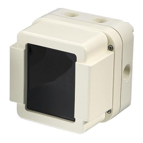
Detectors Incorporated D381 User manual

MAN‐D381‐0001
1
INSTRUCTION MANUAL
Detectors Incorporated
Model D381 General Application
Flame Detector

MAN‐D381‐0001
2
TableofContents
INTRODUCTION.………………………………………………………….. 3TROUBLESHOOTING………………………………………………………14
ProductDescription………………………………………………3
Specifications………………………………………………………..4EVENTLOGSANDFireGraphs………………………………..14
General…………………………………………………………………4
Electrical……………………………………………………………….4ACCESSORIES………………………………………………………..14
Environmental……………………………………………………… 4
Mechanical…………………………………………………………… 4PRODUCTSUPPORT……………………………………………….14
INSTALLATION………………………………………………………5TechnicalSupportandCustomerSupport……………….14
DetectorDimensions……………………………………………. 5
MountingtheDetector………………………………………… 5WARRANTY………………………………………………………….15
Positioning…………………………………………………………… 5
UsingSwivelMountingBracket……………………………. 5APPENDIX“A”
DirectMounting…………………………………………………… 5OrderingInformation…………………………………………….16
InstallationTips…………………………………………………….5,6
DetectorConfiguration………………………………………… 6APPENDIX“B”…………………………………………………….17
DetectorWiring…………………………………………………….6‐8
DETECTORSENSOR,LEDINDICATIONS
ANDCONDUITENTRYLOCATION………………………… 9
OPERATIONANDSTARTUP………………………………….10
DetectorPerformanceandResponse……………………10
DetectorOperation………………………………………………10
DetectorVisualIndicators…………………………………….10
NormalOperation………………………………………………..10
AlarmCondition…………………………………………………..11
FaultCondition…………………………………………………….11,12
DetectorSelf‐Test………………………………………………..12
DetectorOpticalPathTest…………………………………..12
MAINTAINANCE…………………………………………………..12
InspectionandCleaning……………………………………….12
DetectorTestingProcedures………………………………..12
PeriodicTesting…………………………………………………….12
ManualTest………………………………………………………….13
D383DETECTORRESPONSE
CHARACTERISTICS…………………………………………………13
PerformanceTesting………………………………………………13
ImmunitytoFalseAlarms……………………………………13,14

MAN‐D381‐0001
3
1.0 Introduction
1.1 ProductDescription
TheDetectorsInc.modelD381isanewgenerationof
general‐purposeandmediumrangeMulti‐Spectrum
3IR + UV flame detector designed for detection of
firesinmultitudeofindoorandoutdoorapplications.
The Model D381 senses the Ultraviolet radiation in
UV spectrum and Infrared radiation in 3 discrete
bandsofIRintherangeof2‐5microns.Thedetector
will respond to Hydrocarbon and non‐Hydrocarbon
basedfireswithin3seconds.
The Model D381 is a stand‐alone flame detector in
watertight NEMA 4 (IP67) and explosion‐proof
aluminum enclosure designed for Class I, Division 2
(Zone 2) installations. The detector offers multiple
outputs including two fire alarm relays, 4‐20 mA
analogandRS485ModBusRTU.
Thedetectorcanbeusedasastand‐alonedeviceor
canbeinterfacedwithanyapprovedfirealarmpanel,
controlsystem,orPLC.TheD381detectorfeatures
anAutomaticSelf‐Testforcontinuously monitoring its sensors and electronics. Additionally, the detector is
equippedwithOptiRadarfeaturethatcontinuouslychecksthedetector’sopticalpathintegrityandthewindow
blockagebyexternalobjects.ThisfeaturewillinitiateaFaultsignalifanyobjectisblockingtheviewingwindow
within1”ofdetector.

MAN‐D381‐0001
4
1.2 Specifications
1.2.1 General
Field‐of‐View: 90°Horizontal&Vertical
SpectralSensitivity: UV: 180‐260nanometers
IR: 2‐5microns(3discretebands)
SensitivityRange: Low&High
ResponseTime: Alarm: 3‐5Seconds
DetectionRange: 1’x1’n‐Heptanefire:80feet
1.2.2 Electrical
OperatingVoltage: 24VDCnominal(18‐31),Regulated
PowerConsumption: Standby:60mA@24VDC
Alarm:90mA@24VDC
RelaysOutputs: Alarm&AuxiliaryRelays:
SPDT—contactsrated2A@24VDC
De‐EnergizedwithN.O.contacts(powerapplied)
Auxiliaryrelaysettings:0.3,3,10,20seconds
FactoryDefaultforAux.relay:3seconds
Faultrelay:
SPST–contactrated2A@24VDC
EnergizedwithN.C.contact(powerapplied)
AnalogOutput: 0‐20mAStepped‐Source
Communication: RS485ModBus
VisualIndications: GreenLED–NormalOperation
RedLED‐Alarm
AmberLED‐Fault
Wiring Integral15‐conductorpre‐wiredcableharness
20AWG,10’long
1.2.3 Environmental
HumidityRange: 5to95%relativehumidity,non‐Cond.
TemperatureRange: ‐40to+185°F(‐40to+85°C)
EnclosureType: NEMA4,IP67
1.2.4 Mechanical
EnclosureMaterial: Aluminum,powdercoated
Weight: 2lbs.(0.9kg)
ConduitEntry (1)M25–M25X3/4"adapteravailable
Mounting: Swivelbracket—Optional

MAN‐D381‐0001
5
2.0 Installation
2.1 DetectorDimensions
TheD381detectorissuppliedwithpowdercoatedAluminumenclosure.Theenclosurehas(4)7mm
holesintherearmountingflange(Figure1)thatcanbeusedtomountthedetectordirectlyonaflat
surfaceorontotheoptionalswivelmountingbracketthatallowsthedetectoradjustmentinverticaland
horizontalaxis.
Figure1–DetectorDimensions
2.2 MountingtheDetector
2.2.1 Positioning‐Thedetectorshouldbeinstalledsuchthatthecenterofthedetector’sfield‐of‐view
isaimeddirectlyatthecenteroftheareatobeprotected(hazardarea).Detectorsshouldbe
installedwithnoobstructionoftheField‐of‐View.
2.2.2 UsingSwivelMountingBracket–Thismethodwillallowthedetectortobeadjustedinvertical
andhorizontalaxisforoptimumorientation.First,securetheSwivelMounttothesurfacetobe
mounted.Nextattachthedetectorontotheswivelmountingbracketusingboltssupplied.
2.2.3 DirectMounting.‐Thedetectormayalsobemounteddirectlytoaflatsurfaceusingthe(4)7
mmmountingholesontherearmountingflangeandsecureitfirmlywith(4)steelscrews.
2.2.4 InstallationTips:‐Wheninstallingthedetectors,beawareofthefollowingconditions:
a) Field‐of‐Viewofdetectorsshouldnotbeblockedbyanyobjectsforoptimumperformance.
b) Thedetectorshouldbeinstalledsuchthatthecenterofthedetectorisaimedatthecenter
oftheareatobeprotected(hazardarea).Detectorsshouldbeinstalledabovethehazard

MAN‐D381‐0001
6
areapointingdownwardatananglebetween35‐55degreesfromhorizontalwithno
obstructionoftheField‐of‐View.Detectorheightgenerallyshouldbeapproximately1½to
2½timestheheightoftallestobjectinthehazardarea.Theheightmayvarydependingon
theapplication,indoor/outdoorinstallationandsizeofthehazardarea.Detectorshouldbe
easilyaccessibleformaintenance.
c) Forindoorapplications,thedetectorsshouldbeinstalledsothattherearenohighintensity
lightsintheviewofdetectors.Highintensitylightsmaydiminishdetectorsensitivity.
d) Detectorsshouldbeinstalledsothattheyareeasilyaccessibleformaintenance.
2.3 DetectorConfiguration
2.3.1 Unlessspecifiedotherwise,theD381detectorsareshippedfactoryconfiguredasdescribedbelow:
FireAlarmRelay: SPST,NormallyDe‐Energized,N.O.,Non‐Latching
WarningRelay SPST,NormallyDe‐Energized,N.O.,Non‐Latching
FaultRelay: SPST,NormallyEnergized,N.C.,Non‐Latching
4‐20mA SteppedAnalog,Sourcing
Communication ModBusRTUProtocol
2.3.2 Allrelayswithstandardfactoryconfigurationare“Non‐Latching”.If“Latching”modeisrequired,
itmustbespecifiedwhenordering.PleaserefertoAppendix“A”forotherconfigurationoptions.
2.3.3 Maximumloopresistancefortheanalogoutputis800Ohms
2.3.4 TheD381DetectorisalsoequippedwithastandardRS485ModBuscommunicationprotocolfor
interfacingwithdevicesorcontrollersusingtheModbusstandard.TheRS485communication
protocolisalsousefulincommunicatingwithdetectorforviewingordownloadingEventLogsand
FireGraphsusingalaptopandtheLabVIEWprogrammingsoftware.
2.4 DetectorWiring
2.4.1 The D381 Detector issupplied with an integral multi‐conductor shielded cable with Individual
conductorscolor‐codedforeasyidentification(Table1).
2.4.1 DetectorshouldbewiredinaccordancewiththeNationalElectricalCode(NFPA70)Division2
hazardous (Classified) locationwiring procedure inthe United Statesoraccordingtothelocal
codesinothercountries,observingtherequirementsforElectricalSafety.
2.4.2 Terminate each color‐coded wire to an appropriate terminal in the Fire Alarm Panel, PLC, or
ControlSystem.Figure3showsthebasicwiringconfigurationsforthedetector

MAN‐D381‐0001
7
Table 1 - D381 Detector Wiring Identification
Wire
Number
Wire
Color
Description
3 Red 24 VDC (+)
1 Black 24 VDC (Return)
8 Red/Black Alarm Relay Contact A (COM)
13 Red/White Alarm Relay Contact B (N.O.)
4 Green Fault Relay Contact A (COM)
9 Green/Black Fault Relay Contact B (N.O.)
5 Orange Auxiliary Relay Contact A (COM)
10 Orange/Black Auxiliary Relay Contact B (N.O.)
2 White ModBus RTU (+)
7 White/Black ModBus RTU (-)
6 Blue 4-20 mA (+)
11 Blue/Black Test
12 Black/White Not Used
14 Green/White Not Used
15 Blue/White Not Used
Cable
Shield
To be terminated at chassis ground of PLC or Fire Alarm Panel

MAN‐D381‐0001
8
2.5 BasicWiringSchematics

MAN‐D381‐0001
9
3.0 DetectorSensors,LEDIndicatorsandConduitEntryLocation

MAN‐D381‐0001
10
4.0 Operation&Start‐Up
4.1 DetectorPerformance&Response
TheD381isaMulti‐SpectrumUV/IR/IRmediumrangeflamedetectoroptimizedforuseinvarietyof
indoor/outdoorapplicationsinClassI,Division2areainstallationsthedetectorincludesahighly
sensitiveUVsensorand3separateQuantumIRsensorstunedpreciselyto3separatebandsofIR
radiationintheelectromagneticspectrumforrespondingtovarioustypesoffires.Thedetectorwill
respondtobothHydrocarbonandNon‐Hydrocarbonwithin3‐5seconds,theresponsetimewilldepend
onthesizeoftheflame,typeoffuel,andthedistancefromtheflame.
4.2 DetectorOperation
Oncepoweredup,theD381detectorwillgothroughitsself‐diagnosticsprocessandwillbereadyfor
operationafter10‐12seconds.Duringtheself‐diagnosticprocess,theGreen,Amber,andRedLEDswill
turnonsequentiallyindicatingthisprocess.Duringtheself‐diagnostics,theMicroprocessorwillcheck
thestatusofUVandIRsensors,relays,variousdevices,andtheself‐testfeature.Oncethe
Microprocessordeterminesthatalldevicesandfunctionshavebeentestedandfoundtobewithinthe
specifications,itwillthenterminatetheself‐testdiagnosticsandwillreturnthedetectortonormal
operation.Duringthenormaloperation,theGreenLEDwillbeturn“ON”for1secondand“OFF”for1
secondindicatingthatthedetectorisnowreadytodetectfires.
4.3 DetectorVisualStatusIndications
TheD381detectorhas(3)brightLEDsforindicatingthestatusofthedetector:
GreenLED NormalOperation
REDLED AlarmCondition
AmberLED Faultcondition
4.3.1
NormalOperation:
DuringthenormaloperationandwithnoAlarmorFaultexisting,thedetectorwillturnthe
GreenLED“ON”for1secondand“OFF”for1secondindicatingnormalstatus.Unlessotherwise
specifiedthedetectorwillbeshippedwiththefollowingstandardfactoryoutputconfiguration
withpowerapplied:
Alarmrelay NormallyDe‐Energized,N.O.Contacts
Auxiliaryrelay NormallyDe‐Energized,N.O.Contacts
Faultrelay NormallyEnergized,N.C.Contacts
Analogoutput 4.0+/‐0.2mA–Normaloperation
Relaymodes Non‐Latching

MAN‐D381‐0001
11
4.3.2
AlarmCondition:
WhentheD381detectorisexposedtofiresanddeclaresanAlarm,thefollowingconditionswill
occur(withstandardfactoryconfigurations):
RedAlarmLED Willturn“ON”steady
GreenLED Willcontinueflashing“ON”and“OFF”
Alarmrelay Willbeactivated
Auxiliaryrelay Willbeactivated
Faultrelay Willremainunchanged
Analogoutput 20.0+/‐0.2mA
ModBusoutput Willdeclare“Alarm”command
PleasenotethattheRedAlarmLEDwillremain“ON”andtheAlarmrelaywillremainEnergized
aslongthefireispresent.Oncethefirehasbeenextinguishedthedetectorstatuswillbeas
follows:
a) Non‐LatchingAlarmRelaymode:ThedetectorwillautomaticallyresetitselfbyDe‐
EnergizingtheAlarmandAuxiliaryRelays,turningofftheRedLED,switchingtheanalog
outputto4mAandremovingtheAlarmcommandfromModBusoutput
b) LatchingAlarmRelaymode:ThedetectorstatuswillremainunchangedwithAlarmand
AuxiliaryrelaysstillEnergizedandtheRedAlarmLEDremaining“ON”untilthedetectoris
resetbyrecyclingthe24VDCpowertodetectormomentarily.Thedetectorshouldnow
returntoNormaloperation.
4.3.3
FaultCondition:
AFaultmayoccurifoneormoreofthefollowingconditionsexist(withstandardfactory
configurations):
FaultyUVorIRSensor
FaultyMicroprocessor
FaultyRelay
Lowinputpower(lessthan19VDC)
Highinputpower(higherthan34VDC)
Hightemperature
Dirtyviewingwindow
Blockageofdetector’swindow
DuringdetectorFaultthefollowingconditionswilloccur(withstandardfactoryconfigurations):
AmberLED Willturn“ON”steady
GreenLED Willcontinueflashing“ON”and“OFF”
Faultrelay WillbeDe‐Energized(deactivated)
Analogoutput 2.0+/_0.2mA–DirtyWindow
Analogoutput 0.3–0.9mA–OtherFaults
ModBusoutput Willdeclare“Fault”Command

MAN‐D381‐0001
12
a) Non‐LatchingFaultRelaymode:WhentheFaulthasbeencleared,thedetectorwill
automaticallyresetitselfbyturningofftheAmberLEDandEnergizingtheFaultrelay.
b) LatchingFaultRelaymode:ThedetectorstatuswillremainunchangedwithFaultrelaystill
De‐EnergizedandtheAmberFaultLEDremaining“ON”untilthedetectorisresetby
recyclingthe24VDCpowertodetectormomentarily.
4.3.4
DetectorAutomaticSelf‐Test:
TheD381detectorisprogrammedtoperformanautomaticdiagnosticself‐testperiodically
(factorydefaultisevery5minutes).DuringtheautomaticSelf‐Test,thedetectorwillturnon
bothAmberLEDsflashingforseveralsecondsindicatingtheself‐testprocess.Duringtheself‐
testprocess,thedetectorwillturnonitsinternalUVandIRtestsourcesmomentarilywhichwill
bereflectedfromtheSapphirewindowbackintotheUVandIRsensorsforanalysis.Following
theautomaticSelf‐Test,thedetectorwillreturntoNormalOperationifnoFaultwasdetected.
4.3.5
DetectorOpticalPathTest:
Thedetectoralsomonitorsthecleanlinessofitsviewingwindowandblockageofitsviewing
windoweverysecondusingtheOptiRadarfeature.Ifthecontaminationofthewindowexceeds
thepresetthreshold,thedetectorwilldeclareaFault.Thedetectoralsomonitorstheblockage
ofthewindowbyexternalobjects.Ifanobjectisplacedwithin1”ofdetector’swindow,the
detectorwillturnonitsAmberlightflashingfor60seconds;andiftheblockageisnotremoved
after60seconds,thedetectorwilldeclareaFaultbychangingtheflashingAmberlighttosteady
on.
5.0 Maintenance
5.1 InspectionandCleaning
Oncethedetectorhasbeeninstalledandpoweredup,itshouldprovidemaintenancefreeperformance
foryears.Thefollowingisasimpleguidelineforkeepingthedetectorworkingandtroublefree:
5.1.1 TheD381detectorrequiresnofieldcalibrationoradjustment.
5.1.2 The detector and the viewing window should be kept clean from dirt, dust, oil and other
contaminantsatalltimes.Disconnectpowerbeforecleaningthedetector’swindow.Toremove
dirtanddustusesoftcottonandsoapywaterandrinsethewindowwithcleanwater.Asoftcloth
andIPA(IsopropylAlcohol)canbeusedtoremoveoilandotherresiduesfromthewindow.
5.2 DetectorTestingProcedure
5.2.1
PeriodicTesting:
Thedetectorshouldbefunctionallytestedend‐to‐endannuallyorasrequired
bylocalcodesorauthoritieshavingjurisdiction.Priortotestingthesystem,alldetectoroutputs
toFireAlarmPanelorextinguishingsystemsshouldbedisabledordisconnected.Thefunctional
testshouldbeperformedbyqualifiedpersonnelbeingfamiliarwiththesystem.

MAN‐D381‐0001
13
5.2.2 ManualTest:InadditiontothecontinuousAutomaticSelf‐Test,theD381detectorscanbetested
manuallyonaperiodicbasis.ReferringtoFig.3,DetectorWiringSchematic,themanualtestcan
beinitiatedbymomentarilyconnectingwireBlue/Black(Test)to24VDC(return)ofpowersupply.
Tofacilitatethemanualtest,Amomentarypushbuttonswitchcanbeinstalledandlocatedatthe
FireAlarmpanelorControlCenter.
6.0 D381DetectorResponseCharacteristics
6.1 PerformanceTesting
TheD381detector,likeanyotherflamedetectors,willrespondtovarioustypesoffiresdifferentlyboth
intimeanddistance.Forthisreason,theFactoryMutual(FM)baselineperformancetestingisperformed
forallflamedetectorsusing1ft.x1ft.n‐Heptanepanfireforfuelfiresand30”‐36”highplumefireforgas
flames.Thisprocedurewouldallowtheend‐usersameansofcomparingtheflamedetectorsofvarious
manufacturersforresponsetimeandsensitivity.Belowistheresponse characteristic of the D381
detectorastestedandwitnessedbyFM:
Table2–D381DetectorResponse@HighSensitivity‐Indoor
FuelType FlameSize Distance
(ft/m)
Response
Seconds(Average)
n‐Heptane 2”Dia. 11.75/3.6 3.2
n‐Heptane 12”x12” 80/24.4 5.4
IPA 12”x12” 80/24.4 4.2
JP4 12”x12” 40/12.2 5.7
Hydrogen 36”plume 60/18.3 4.7
6.2 ImmunitytoFalseAlarmSources
DetectorD381ishighlyimmunetomanyfalsealarmsourcestested.Belowtablesaresamples
ofFalseAlarmImmunitytovarioussourcesandthedetectorresponsetimeinthepresenceof
falsealarmsources:
Table3–D381DetectorFalseAlarmImmunity@HighSensitivity
FalseAlarmSource Distance
Unmodulated Modulate
Sunlight ‐ NoResponse NoResponse
IncandescentLamp–60W 3ft/0.91m NoResponse NoResponse
InfraredHeater–1500W 3ft/0.91m NoResponse NoResponse
SodiumVaporLamp–150W 3ft/0.91m NoResponse NoResponse
FlorescentLamp–22W 3ft/0.91m NoResponse NoResponse
HalogenLamp–500W 3ft/0.91m NoResponse NoResponse
MagFlashlight 3ft/0.91m NoResponse NoResponse
Heater–6kW 3ft/0.91m NoResponse NoResponse
ArcWelding 30ft/9.1 NoResponse NoResponse

MAN‐D381‐0001
14
Table4–D381DetectorResponseinthePresenceofFalseAlarmSource
FalseAlarmSource FireSizeand
Fuel
Distance
(ft./m)
Unmodulated
ResponseTime
Seconds(Ave.)
Modulate
ResponseTime
Seconds(Ave.)
Sunlight 12”x12”n‐Heptane 80/24.4 5.7 2.5
IncandescentLamp–60W 2”Dia.n‐Heptane 9.75/2.97 2.7 3.3
InfraredHeater–1500W 2”Dia.n‐Heptane 9.75/2.97 2.5 2.3
SodiumVaporLamp 2”Dia.n‐Heptane 9.75/2.97 3.9 1.6
FlorescentLamp 2”Dia.n‐Heptane 9.75/2.97 3.8 3.0
HalogenLamp–500W 2”Dia.n‐Heptane 9.75/2.97 3.5 7.3
MagFlashlight 2”Dia.n‐Heptane 9.75/2.97 2.8 2.9
Heater–6kW 2”Dia.n‐Heptane 9.75/2.97 2.9 2.8
ArcWelding 2”Dia.n‐Heptane 30/9.1 10.0 10.4
7.0 Troubleshooting(tobeaddedlater)
8.0 EventLog&FireGraph(tobeaddedlater)
9.0 Accessories(tobeaddedlater)
10.0 ProductSupport
10.1 TechnicalSupportandCustomerSupport
ForTechnicalandCustomerSupportandquestionsconcerningthedetectorsorapplications,
pleasecontact:

MAN‐D381‐0001
15
11.0 Warranty
DetectorsIncorporatedwarrantstheproductsmanufacturedandsuppliedbyDetectorsIncorporated
againstdefectsinmaterialsandworkmanshipundernormaluseandserviceforaperiodoffive(5)
yearsfromthedateofshipment.DetectorsIncorporatedatitssolediscretionwillrepairorreplaceat
nochargeanyproductsfoundtobedefectiveduringthewarrantyperiod.Thedefectiveproductmust
beshippedtransportationpaidtoDetectorsIncorporatedorDistributor/Representativewherethe
productswaspurchased.ThisexpresslimitedwarrantyisextendedbyDetectorsIncorporatedtothe
originalpurchaseronlyandisnotassignableortransferabletoanyotherparty.
Thiswarrantydoesnotcoverthefollowing:
1. Damageincurredintransit.
2. Defectsordamagefrommisuse,accident,“ActofGod”,orneglect.
3. Defectsordamagefromimproperinstallation,lackofmaintenance,impropertestingand
operation.
4. Defectsordamagecausedbyalterations,unauthorizeddis‐assemblies,repairsormodifications.
5. Damagescausedbyapplyinghighvoltage,electricalpowersurgeorfaultypowersupplies.
6. Transportationchargestoandfromrepairfacility.
7. Illegalorunauthorizedalterationsofthefirmware/softwareintheproduct.
ThisisthecompletewarrantyfortheproductsmanufacturedbyDetectorsIncorporated.Exceptfor
thewarrantyexpressedabove,DetectorsIncorporateddisclaimsallotherwarrantiesexpressor
impliedwithregardstoitsproductssold.DetectorsIncorporatedsoleliabilityunderthiswarrantyis
limitedonlytorepairorreplacementoftheproductsandshallnotincludeanyliabilityfor
consequentialorotherdamagesarisingfromtheuseoftheproduct.

MAN‐D381‐0001
16
APPENDIX“A”

MAN‐D381‐0001
17
APPENDIX“B”
Table of contents
Other Detectors Incorporated Security Sensor manuals

