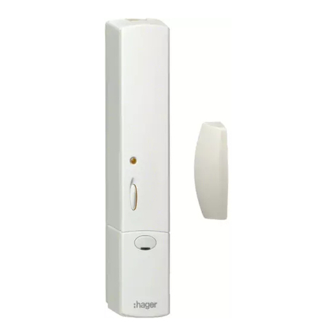
hager TRC301B User manual

1Détecteur
ATouche et voyant
BCache vis
CContact magnétique
intégré
2Porte-aimant
3Contact déporté
1Melder
ATaste und
Kontrollleuchte
BSchrauben-Abdeckung
CIntegrierter
Magnetkontakt
2Magnethalter
3Ausgelagerter Kontakt
1Detector
AKey and indicator
BScrew cover
CBuilt-in magnetic
contact
2Magnet holder
3Remote contact
1Rilevatore
ATasto
e spia
BCoprivite
CContatto magnetico
integrato
2Portamagnete
3Contatto remoto
1Porte-aimant
ACapot
BAimant
CSocle
2Détecteur
3Cales d’épaisseur
1Magnethalter
AAbdeckung
BMagnet
CSockel
2Melder
3Unterlegkeil
1Magnet holder
Auard
BMagnet
CBase plate
2Detector
3pacer
1Portamagnete
ACopertura
BMagnete
CZeppe di spessore
2Rilevatore
3Zeppa di spessore
1Contact sur le dormant
aCapot
bContact
cSocle
fCales
1Kontakt an der Zarge
aAbdeckung
bKontakt
cSockel
fUnterlegkeile
1Contact on the frame
auard
bContact
cBase plate
fSpacers
1Contatti sul fisso
aCopertura
bContact
cZoccolo
fZeppa di spessore
2Contact sur l’ouvrant
aCapot
dAimant
eSocle
fCales
2Kontakt am Fensterflügel
aAbdeckung
dMagnet
eSockel
fUnterlegkeile
2Contact on opening
auard
dMagnet
eBase plate
fSpacers
2Contatti sul battente
aCopertura
dMagnete
eZoccolo
fZeppa di spessore
1 6T7992B
TRC301B
6T7992B
aDétecteur d’ouverture radio
eFunk-Öffnungsmelder
zOpening radio detector
yRilevatore d’apertura radio
AAA LR03
Fixation / Montage / Fixing / Fissaggio
C
Description / Produktbeschreibung / Description / Descrizione
AOuverture/ Öffnen/ Opening / Apertura
B
Porte-aimant / Magnethalter / magnet holder / Portamagnete
A
B
C
Max. 5 mm
C
2
3
1
Contacts déportés / Ausgelagerte Kontakte/ Remote contacts/ Contatti remoti
Positions des aimants
Position des Magneten
Magnet location
Posizione del magnete
a
d
5 mm max.
1
2
b
c
a
f
e
d
V2.7.0
RFTP 230V~ Bus
30 V

3 6T7992B
Description du produit
Le détecteur d’ouverture TRC301B est un émetteur
radio KNX alimenté par pile. Il permet de signaler
sur le bus l’ouverture d’une fenêtre ou d’une porte.
Cette information peut aussi être utilisée pour
lancer une commande KNX: mise en hors gel du
chauffage, montée du volet, scène etc.
Le détecteur est équipé:
• d’un contact magnétique intégré
• d’un bornier permettant le raccordement d’un
contact déporté.
Fonctions
Le TRC301B dispose d’un mode de
fonctionnement automatique qui permet l’émission
KNX sur chaque changement d’état du contact.
Selon la configuration effectuée, 1 ou plusieurs
informations seront émises.
Il est possible d'interrompre le mode automatique
(ex : pour ouvrir une fenêtre sans couper le
chauffage), pour cela, appuyer sur la touche A.
Le voyant passe au rouge durant 1 seconde. Pour
remettre le détecteur en fonctionnement Auto
appuyer à nouveau sur la touche A, le voyant
passe au vert durant 1 seconde.
Les fonctions précises de ces produits dépendent
de la configuration et du paramétrage.
Ouverture
1Dévisser la vis à l’aide d’un tournevis cruciforme
2Déclipser le capot du socle
3Insérer 2 piles alcalines AAA LR03
Le changement de piles n’a aucune influence sur la
configuration du produit.
Fixation
Choix de l’emplacement
Le détecteur doit être placé:
• à l’intérieur
• de préférence fixé sur le dormant de l’ouvrant à
au moins 1 m du sol
• éloigné de tout source de parasites (compteur
électrique, masse métallique etc.)
• sur une surface plane.
GDans le cas d’une fixation sur support
métallique, insérer une cale de bois ou de
plastique de 20 mm d’épaisseur entre le socle
et le bâti métallique.
Fixation du détecteur
Fixer le socle avec 2 vis adaptées au support ou
avec de l’adhésif double face.
En cas d'utilisation du contact déporté,
choisir un embout passe-câble adapté à la section
de votre câble.
Grappe de passe-câbles :
A
B
4 possibilités de montage :
Fixation du porte-aimant
Lorsque l’ouvrant est fermé, le porte-aimant doit
être positionné en face du contact d’ouverture
incorporé à moins de 5 mm de celui-ci.
Aligner l’encoche verticale sur le porte-aimant avec
la flèche située sur le socle du détecteur.
GL’alignement latéral et l’ajustement en hauteur
sont impératifs pour un fonctionnement
correct du détecteur.
Ajuster la hauteur du porte-aimant selon les
schémas .
Si nécessaire, utiliser les cales de surépaisseur
livrées pour le porte-aimant ou positionner une
cale sous le détecteur d’ouverture 2(non
fournie).
Fixer le socle du porte-aimant, placer l’aimant à
l’intérieur du capot et le clipser sur le socle.
Clipser, puis visser le
détecteur sur son socle.
Positionner le cache de la
vis (livré sur grappe du
porte-aimant) sur le
capot.
Pour déclipser le capot
du porte-aimant, insérer
un petit tournevis plat
dans l’encoche prévue et
faire un mouvement de
rotation.
Fixation et raccordement du contact déporté
Voir schémas et .
GL’utilisation des contacts D8931 et D8932
nécessite de raccorder les brins de couleur
bleu et vert uniquement.
Récapitulatif des distances
d’ouverture et de fermeture
Les distances d'ouverture et de fermeture entre le
détecteur multicontact et l'aimant à partir desquels
le contact incorporé analyse le changement d'état
de l'issue sont indiquées dans le tableau .
Configuration
Cet émetteur peut être configuré de 3 façons
différentes :
•quicklink&configuration sans outil: voir notice
de configuration livrée avec les récepteurs radio.
• E-mode TX100/B V.2.7.0 ou >: descriptif des
fonctions du produit disponible chez le
constructeur.
• S-mode ETS via TR131 : logiciel d’application
STRC301B. Base de données et descriptif
disponible chez le constructeur.
Faites un appui sur la touche Rlors de la phase
d'apprentissage pour le TX100 ou pour l'adressage
en ETS (Voir schéma ).
C E
D
F
C
C
élection des entrées
• Entrée 0: détection d’ouverture - indication d’état
(non disponible en quicklink&)
• Entrée 1: contact fonction interrupteur.
En mode configuration, la sélection des entrées
se fait par un appui court sur la touche A
pour l’entrée 0 et par un appui long > 5 sec. pour
l’entrée 1.
GPour changer de mode de configuration,
il faut obligatoirement faire un “retour usine” du
produit.
ignalisation du voyant A
Contact déporté
Pour augmenter, les capacités du détecteur il est
possible de raccorder un contact déporté (contact
libre de potentiel, aucune tension ne doit être
appliquée sur les entrées filaires).
Les deux contacts (fenêtre + contact déporté) sont
alors traités comme une fonction logique "OU".
Pour activer la détection par le contact déporté, il
faut actionner au moins une fois sa fenêtre.
Pour retirer un contact déporté déjà activé,
il faut faire un reset du produit en retirant les piles
durant 30 s.
Retour usine
Appuyer et maintenir le le bouton poussoir R
jusqu'au clignotement de la LED cfg (>10s) puis
relâcher.
La fin du retour usine est signalée par l'extinction
de la LED cfg.
Cette opération provoque l'effacement complet de
la configuration du produit. Après un “retour
usine”, attendre 15 s avant de procéder à une
configuration.
Accessoires
D8924 Contact d'ouverture saillie avec bornier,
filaire.
D8931 Contact d'ouverture universel, protégé,
blanc, filaire.
D8932 Contact d'ouverture universel protégé
brun, filaire.
Accessoires non disponibles sur tous les marchés.
Possibilité d'utiliser d'autres contacts à aimant
libre de potentiel (fonctionnement non garanti).
Utilisable partout en Europe
å
et en Suisse
Par la présente hager Controls déclare que le détecteur
d’ouverture radio est conforme aux exigences
essentielles et aux autres dispositions pertinentes des
directives basse tension 2006/95/EC et CEM
2004/108/EC.
La déclaration CE peut être consultée sur le site:
www.hagergroup.net
°
¢
13
2
5 mm
max.
70 mm
alignement
encoche-flèche
Recommandations
Tout accès aux composants internes peut
endommager le produit par décharges
d’électricité statique.
Lors d’une intervention sur le produit prendre les
précautions suivantes:
• Eviter tout contact direct ou par l’intermédiaire
d’un outil métallique, avec les composants
électroniques.
• Utiliser des outils non magnétiques.
• Avant d’accéder aux composants internes,
toucher une surface métallique non peinte telle
qu’une canalisation d’eau ou un matériel
électrique relié à la terre.
• Limiter aux maximum les déplacements entre
deux accès aux composant internes. Sinon
répéter l’opération ci-dessus avant chaque
nouvelle intervention sur le produit.
Piles faibles - Clignotement rouge 1 sec.
Mode
automatique
sur ouverture/
fermeture fenêtre
- Clignotement orange
1 sec. si aucun lien n’est
configuré
- Flash vert 100 ms si lien
configuré
Changement de
mode par appui
sur touche A
Auto →Arrêt
Arrêt →Auto. - Allumé rouge 1 sec.
- Allumé vert 1 sec.
Cache
Appareil à installer uniquement par
un installateur électricien selon les normes
d’installation en vigueur dans le pays.
Respecter les règles d’installation TBTS.
Ne pas installer ce module à l’extérieur du
bâtiment.

Auswahl der Eingänge
• Eingang 0: Öffnungsmeldung – Statusanzeige
(nicht verfügbar in quicklink&)
• Eingang 1:Kontakt Schalterfunktion.
Im Konfigurationsmodus erfolgt die Auswahl
der Eingänge durch kurzen Druck auf Taste A
für Eingang 0 und einen langen Druck
(> 5 Sekunden) für Eingang 1.
GUm den Konfigurationsmodus zu ändern,
ist das Gerät obligatorisch auf
"Werkseinstellungen" zuruckzusetzen.
Meldungen der Kontrollleuchte A
Ausgelagerter Kontakt
Um die Kapazitäten des Melders zu erhöhen, lässt
sich ein ausgelagerter Kontakt (spannungsfreier
Kontakt, es darf keine Spannung an den
verkabelten Eingängen anliegen) anschließen.
Die beiden Kontakte (Fenster + ausgelagerter
Kontakt) werden dann als logisches „ODER”
behandelt. Um den Meldebetrieb des
ausgelagerten Kontakts zu aktivieren, ist das
Fenster mindestens einmal zu betätigen.
Um einen bereits aktivierten ausgelagerten Kontakt
zu entfernen, muss das erät zurückgesetzt
werden. Dazu für 30 s die Batterien entnehmen.
Zurücksetzen auf Werkseinstellungen
Taster Rdrücken und gedrückt halten, bis die
LED cfg blinkt (>10 Sekunden), dann loslassen.
Das Zurücksetzen auf Werkseinstellungen wird
durch das Erlöschen der LED cfg angezeigt.
Bei dieser Aktion wird die komplette Konfiguration
des erätes gelöscht. Nach dem Rucksetzen auf
Werkseinstellungen ist eine Wartezeit von
15 Sekunden abzuwarten, bevor die Konfiguration
vorgenommen werden kann.
Zubehör
D8924 Öffnungskontakt, Aufputzgerät mit
Klemmleiste, verdrahtet
D8931 Universal-Öffnungskontakt, geschützt,
weiß, verdrahtet
D8932 Universal-Öffnungskontakt, geschützt,
braun, verdrahtet
Zubehör nicht in allen Ländern erhältlich. Die
Möglichkeit zum Einsatz zusätzlicher spannungs-
freier Magnetkontakte ist nicht gewährleistet.
4 6T7992B
www.hager.com
°
£
Produktbeschreibung
Der Öffnungsmelder TRC301B ist ein
batteriebetriebener KNX-Funksender. Er dient
dazu, dem Bus die Öffnung eines Fensters oder
einer Tür zu melden.
Diese Information kann ebenfalls dazu dienen,
einen KNX-Steuerbefehl anzustoßen:
Frostschutzbetrieb der Heizung, Aufwärts-
bewegung des Rollladens, Szene usw.
Der Melder ist folgendermaßen ausgestattet:
• mit einem integrierten Magnetkontakt
• mit einer Anschlussleiste zum Anschluss
eines ausgelagerten Kontakts.
Betrieb
Der TRC301B hat einen Automatikmodus, mit dem
KNX-Meldungen zu jeder Zustandsänderung des
Kontakts gesendet werden können. Je nach
bewerkstelligter Konfiguration werden eine oder
mehrere Informationen gesendet.
Der Automatikmodus kann unterbrochen werden
(z. B. um ein Fenster zu öffnen, ohne die Heizung
abzustellen). Dazu die Taste Abetätigen. Die
Kontrollleuchte leuchtet 1 Sekunde lang rot. Um
den Öffnungsmelder wieder in den
Automatikmodus zu schalten, erneut die Taste A
betätigen. Die Kontrollleuchte leuchtet 1 Sekunde
lang grün.
Die genauen Funktionen dieser eräte hängen von
der jeweiligen Konfiguration und den jeweiligen
Parametereinstellungen ab.
Öffnen
1Schraube mit Hilfe eines Kreuzschlitz-
Schraubenziehers lösen
2ehäusedeckel vom Sockel ablösen
32 Alkalizellen einlegen, Typ AAA LR03
Das Auswechseln der Batterien hat keinerlei
Auswirkungen auf die erätekonfiguration.
Montage
Wahl des Einbauortes
Der Melder ist folgendermaßen zu platzieren:
• im Innenbereich
• vorzugsweise an der Zarge des Fensterflügels,
mindestens 1 m über dem Boden
• in ausreichend Abstand von Störsignalquellen
aller Art (Strom-zähler, metallene Masse usw.)
• auf einer ebenen Fläche.
GBei Montage auf Metalluntergrund ist ein Holz-
oder Kunststoffkeil, Stärke 20 mm, zwischen
Sockel und Metallrahmen zu platzieren.
Befestigung des Melders
Sockel mit 2 geeigneten Schrauben oder
mit Doppelklebeband am Untergrund befestigen.
Bei Verwendung eines ausgelagerten Kontakts
einen passenden Kabeldurchführungsanschluss
für Ihren Kabelquerschnitt wählen.
Bündelung von
Kabeldurchführungen :
B
A4 Montagemöglichkeiten :
Montage des Magnethalters
Wenn das Fenster geschlossen ist, ist der
Magnethalter gegenüber dem eingebauten
Öffnungskontakt, in weniger als 5 mm Abstand von
diesem, zu platzieren.
Richten Sie die vertikale Einkerbung des
Magnethalters auf den Pfeil am Sockel des
Melders aus.
GDie seitliche Ausrichtung und die genaue
Höhenabstimmung sind für den einwandfreien
Betrieb des Melders unerlässlich.
Nach Bedarf sind die zusätzlich mitgelieferten
Unterlegkeile für den Magnethalter zu verwenden,
oder es ist ein Keil unter dem Öffnungsmelder zu
platzieren (nicht im Lieferumfang enthalten).
Sockel des Magnethalters montieren, Magneten in
die Abdeckung einlegen und diese auf den Sockel
aufstecken. Melder aufstecken und am Sockel
verschrauben 2.
Schraubenabdeckungen auf
der Abdeckung montieren (an
der Magnethalterung
mitgeliefert).
Um die Abdeckung des
Magnethalters zu lösen, führen
Sie einen kleinen flachen
Schraubenzieher in die hierfür
vorgesehene Einkerbung
stecken und drehen.
Montage und Anschluss der ausgelagerten
Kontakte
Siehe Zeichnungen und .
GWenn die Kontakte D8931 und D8932
verwendet werden, dürfen nur der blaue und
der grüne Draht angeschlossen werden.
Zusammenfassung der Öffnungs- und
chließabstände
Öffnungs- und Schließabstände zwischen dem
Mehrkontaktmelder und dem Magneten, von
welchem aus der eingebaute Kontakt die
Zustandsänderung des Ausgangs analysiert.
(beigefügte Tabelle ).
Konfiguration
Dieser Sender lässt sich auf 3 unterschiedliche
Arten konfigurieren:
•quicklink&-Konfiguration ohne Werkzeug, siehe
die mit den Funkempfängern gelieferte Anleitung.
• E-mode-Konfiguration via TX100/B V.2.7.0
oder >: Beschreibung der erätfunktionen beim
Hersteller erhältlich.
• S-mode (ETS) via TR131: für Nutzer von ETS,
Anwendungssoftware STRC301B. Datenbank
und Beschreibung beim Hersteller erhältlich.
erät durch länger anhaltende Betätigung der
Taste Rin der Lernphase des TX100 oder zur
Adressierungin der ETS-Software in den
Konfigurationsmodus versetzen. (Siehe Zeichnung
).
F
C
D
C E
Überall in Europa
åund in der Schweiz einsetzbar
Hiermit erklärt hager Controls, dass der Funk-Öffnungsmelder
den essentiellen Anforderungen und den anderen maßgeblichen
Bestimmungen der Niederspannungsrichtlinien 2006/95/EC und
CEM 2004/108/EC genügt.
Die CE-Erklärung kann auf folgender Website abgerufen
werden : www.hagergroup.net
Empfehlungen
Der Zugriff auf die internen Bauteile kann zu
Beschädigungen des erätes durch statische
Entladung führen. Wenn Sie das erät öffnen
wollen, sind folgende Vorsichtsmaßnahmen zu
treffen :
• Direkter Kontakt oder Kontakt über ein
Metallwerkzeug mit den elektronischen
Bauteilen.
• Verwenden Sie nichtmagnetische Werkzeuge.
• Bevor Sie die internen Bauteile berühren,
berühren Sie zuerst eine unlackierte
Metallfläche beispielsweise eine Wasserleitung
oder eine geerdete Elektroeinrichtung.
• ehen Sie zwischen zwei Kontakten mit den
internen Bauteilen nicht im Raum umher.
Ansonsten sind vor jedem neuen Eingriff am
Produkt die obigen Schritte zu wiederholen.
Batterien leer - Rot blinkend 1 Sek.
Automatische
Betriebsart
Öffnen oder
Schließen des
Fensters
- Orange blinkend 1 Sek.,
wenn keine Verbindung
konfiguriert ist
- rün blitzend 100 ms,
falls eine Verbindung
konfiguriert ist
Wechsel der
Betriebsart durch
Betätigung der Taste
A
Auto →Inaktiv
Inaktiv →Auto. - Rot leuchtend 1 Sek.
- rün leuchtend 1 Sek.
13
2
5 mm
max.
70 mm
Ausrichtung
Einkerbung - Pfeil
Einbau und Montage dürfen nur durch eine
Elektrofachkraft erfolgen gemäß den einschlä-
gigen Installationsnormen des Landes
erfolgen.
Installationsvorschriften zur Schutzmaßnahme
SELV beachten.
erät nicht für die Verwendung im Freien
umbauen.
Abdeckung
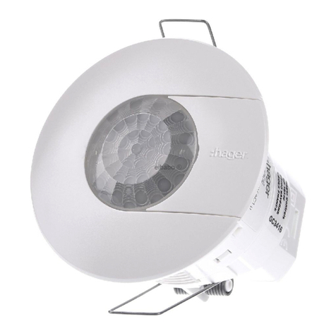
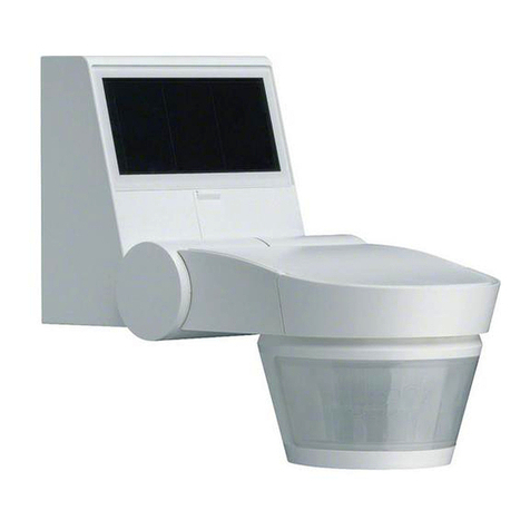
Product description
The opening detector TRC301B is a
battery-powered KNX radio transmitter. It enables
the opening of a window or door to be signalled on
the bus. This information can also be used to
trigger a KNX command: set heating to frost
protection, raise the shutter, change scene etc.
The detector is equipped with:
• a built-in magnetic contact
• a connector block for connection of a remote
contact.
Functions
The TRC301B has an automatic function which can
send a KNX signal on each change of state of the
contact. According to the configuration effected,
1 or more pieces of information will be sent.
It is possible to override the automatic mode (e.g.
to open a window without switching off the
heating). To do this, press key A.
The indicator LED switches to red for 1second.
To return the detector to Auto mode, press again
on key A; the indicator lamp changes to green for
1second.
The specific functions of this product are defined in
its configuration and set-up.
Opening
1Unscrew the product using Phillips screwdriver.
2Pull up the base guard.
3Insert 2 alkaline batteries AAA LR03.
Battery change has no effect on product configu-
ration.
Fixing
election of location
The detector shall be located:
• Inside the building,
• Preferably fitted to the opening frame and at least
1m above the ground,
• Away from any source of interference (electrical
meter, metal mass…),
• On a plane surface.
GWhen fixing on a metal frame, insert a 20mm
thick wood or plastic spacer between the
device base and the metal frame.
Fixing of detector
Fix the base using 2 screws suited to the
supporting materials or double-sided mounting
tape. If a remote contact is used, select a cable
grommet suitable for the cross-section of your
cable.
Cluster of cable grommets:
B
A
5 6T7992B
°
§
4 fixing options
Fixing of magnet holder
When the opening is closed, the magnet holder
shall be positioned opposite the opening built-in
contact with a clearance shorter than 5mm.
Align the magnet holder vertical notch opposite the
arrow located on the detector base.
Gide alignment and height adjustment are
required for correct operation of the detector.
Adjust magnet holder height according to the
diagram . If necessary, use extra thickness
spacers supplied with the magnet holder or
insert a spacer under the opening detector (not
provided).
Fix the base plate of the magnet holder, fit the
magnet inside the guard and clip it onto the base
plate 2.
Clip then screw the
detector on its base
plate.
Fit the screw cover
(supplied on magnet
holder cluster) to the
guard cover.
Insert a small flat
screwdriver in
the notch provided to
remove the magnet
holder, then move it
in rotation.
Fixing and connecting of remote contact
See diagrams and .
GThe use of contacts D8931 and D8932 requires
connecting only blue and green wires.
ummary of opening and closing
distances
The built-in contact of the device uses such
distances between the multicontact detector and
the magnet to record any change of window
position (see attached table ).
Configuration
This transmitter may be configured in 3 different
ways:
•quicklink&: configuration without tool, see
User's Instructions supplied with the radio
transmitters.
• E-mode TX100/B V.2.7.0 or > : Description of
product features is available from the
Manufacturer.
• S-mode ETS via TR131 : for ETS user, application
software STRC301B. Database and description
of software application available from the
Manufacturer.
Press Rpushbutton once at TX100 learning
phase or for addressing in ETS. (See diagram ).
F
E
C
C
D
C
Input selection
• Input 0 : opening detection - state indication
(not available in quicklink&)
• Input 1: function contact switch.
In configuration mode, the inputs are selected by a
short press of key Afor input 0 and a long press
( > 5 seconds) for input 1.
GProduct factory return is required to change
the configuration mode.
Indicator operation A
Remote contact
It is possible to connect a remote contact in order
to increase the capabilities of the detector(floating
contact, no voltage must be applied to the wired
inputs).
The two contacts (window + remote contact) are
handled as an "OR" logic function. To activate
detection by the remote contact, its window must
be activated at least once. To remove an already
active remote contact, the product must be reset
by removing the batteries for 30 sec.
Factory reset
Keep pushbutton Rdown until the LED flashes
(>10s) then release it.
LED cfg turns off when factory reset is completed.
This operation deletes completely product
configuration. After factory return, wait 15s before
doing a new configuration.
Accessories
D8924 Projection opening contact with connector
block, wire.
D8931 Universal opening contact, protection,
white, wire.
D8932 Universal opening contact, protection,
brown, wire.
Accessories not available in all markets. It is
possible to use other floating magnetic contacts
but operation is not guaranteed.
Usable in all Europe
åand in Switzerland
Hereby, hager Controls, declares that this radio opening
detector is incompliance with the essential
requirements and other relevant provisions of low
voltage directives 2006/95/EC and CEM 2004/108/EC.
The CE declaration can be consulted on the site:
www.hagergroup.net
Empty batteries - Red flashing 1 sec.
Automatic mode
Window opening
or closing
- Orange flashing
1 sec. if no link is
configured
- reen flashing 100 ms if
link is configured
Changing the mode
by pressing key A
Auto.→Stop
Stop →Auto. - Lit red 1 sec.
- Lit green 1 sec.
13
2
5 mm
max.
70 mm
Notch-arrow alignment
Recommendations
Contact with the inside components may
damage the device due to static electricity
discharge.
• avoid hand contact, or by means of a metal
tool, with the electronic components or the
metal sections of the connector blocks.
• use nonmagnetic tools,
• before reaching the internal components,
discharge your static electricity by touching an
unpainted metal surface such as a water
pipeline or a grounded electrical device,
• do not make back-and-forth movements while
working on the inside component. If not
possible, repeat the above operations before
any new intervention on the product.
This device is to be installed only by a
professional electrician fitter according to local
applicable installation standards.
Conform to SELV installation rules.
Not to be installed outside.
Cover

6
°
¶
Descrizione del prodotto
Il rilevatore di apertura TRC301B è un trasmettitore
radio KNX alimentato a batteria. Permette di
segnalare sul bus l’apertura di una finestra o di una
porta. Questa informazione può essere utilizzata
anche per lanciare un comando KNX: messa in
antigelo del riscaldamento, salita tapparella,
scenario, ecc.
Il rilevatore è dotato:
• di un contatto magnetico integrato
• di una morsettiera che consente il collegamento
di un contatto remoto.
Funzioni
Il TRC301B dispone di una modalità operativa
automatica che permette la trasmissione KNX ad
ogni cambiamento di stato del contatto. A seconda
della configurazione, saranno trasmesse una o più
informazioni.
È possibile interrompere la modalità automatica
(es.: per aprire una finestra senza disattivare il
riscaldamento), premendo il tasto A.
La spia diventa rossa per 1 sec. Per riportare il
rilevatore in modalità Auto, premere nuovamente il
tasto A,la spia diventa verde per 1 sec.
Le funzioni precise di questo strumento dipendono
dalla configurazione e dalla parametrizzazione.
Apertura
1Svitare la vite mediante un cacciavite cruciforme,
2rimuovere la copertura dello zoccolo,
3inserire 2 pile alcaline AAA LR03.
La sostituzione delle pile non ha nessuna influenza
sulla configurazione del prodotto.
Fissaggio
celta dell’ubicazione
Il rilevatore va collocato:
• all’interno,
• preferibilmente fissato sul controtelaio fisso del
battente ad almeno 1 metro dal suolo,
• lontano da ogni fonte di correnti parassite
(contatore elettrico, massa metallica…),
• su una superficie piana.
GTrattandosi di un fissaggio su supporto
metallico, inserire una zeppa di legno o di
plastica (spessore: 20 mm) fra lo zoccolo e il
basamento metallico.
Fissaggio del rilevatore
Fissare lo zoccolo con 2 viti adatte al supporto
oppure con adesivo double-face.
In caso di utilizzo del contatto remoto, scegliere un
raccordo per boccola adatto alla sezione del cavo
(fare riferimento alle seguenti figure).
Raggruppamento delle
boccole :
A
B
Quattro (4) possibilità di montaggio:
Fissaggio del portamagnete
Quando il battente è chiuso, il portamagnete va
posizionato di fronte al contatto d’apertura
integrato a meno di 5 mm di distanza.
Allineare la tacca verticale sul portamagnete con la
freccia visibile sullo zoccolo del rilevatore.
GL’allineamento laterale e l’adattamento in
altezza sono tassativi per un corretto
funzionamento del rilevatore.
Adattare l’altezza del portamagnete secondo i
seguenti schemi .
Se necessario, utilizzare le zeppe di
sovraspessore consegnate per il portamagnete o
posizionare una zeppa sotto il rilevatore
d’apertura 2(non fornita).
Fissare lo zoccolo del portamagnete, posizionare
il magnete all’interno della copertura e fissarlo
con clip sullo zoccolo .
Fissare con le clip,
dopodiché avvitare il
rilevatore sul suo
zoccolo.
Posizionare lo schermo
della vite (fornito con il
raggruppamento del
portamagnete) sulla
copertura.
Per staccare la copertura
dal portamagnete,
inserire un piccolo cacciavite piatto nell’apposita
tacca ed effettuare un movimento di rotazione.
Fissaggio e raccordo dei contatti remoti
Vedere schemi e .
GL’utilizzo dei contatti D8931 e D8932 richiede
il raccordo dei fili di colore blu e verde
unicamente.
Riepilogo delle distanze d’apertura e
di chiusura
Fra il rilevatore multicontatto e il magnete mediante
quali il contatto integrato analizza il cambiamento
dello stato della finestra (tabella allegata ).
Configurazione
E’ possibile configurare il emittente in 3 modi
diversi:
•quicklink&configurazione senza strumenti :
consultare il libretto fornito con i ricevitori radio.
• E-mode TX100/B V.2.7.0 o superiore: descrizione
delle funzioni del prodotto disponibile presso il
costruttore.
• S-mode ETS via TR131 : Software applicativo
STRC301B. Base di dati e descrizione del
software applicativo disponibile presso il
costruttore.
Mettete lo strumento in modo configurazione
premendo il pulsante Rin fase d’apprendimento
del TX100 oppure per l’indirizzamento in ETS.
(Vedere schema ).
F
D
C E
C
C
elezione degli ingressi
• Ingresso 0: rilevamento apertura – indicazione di
stato (non disponibile in quicklink&)
• Ingresso 1: contatto funzione interruttore.
In modalità configurazione, la selezione degli
ingressi avviene attraverso premendo brevemente
il tasto Aper l’ingresso 0 e premendolo invece a
lungo (> 5 sec.) per l’ingresso 1.
GPer cambiare modo di configurazione,
occorre obbligatoriamente effettuare un
ripristino delle impostazioni di fabbrica dello
strumento.
Funzionamento della spia A
Contatto remoto
Per aumentare le capacità del rilevatore, è
possibile collegare un contatto remoto (contatto
esente da potenziale, nessuna tensione deve
essere applicata sugli ingressi filari).
I due contatti (finestra + contatto remoto) sono
allora considerati come una funzione logica "OR".
Per attivare il rilevamento tramite il contatto
remoto, occorre azionare almeno una volta la
relativa finestra. Per rimuovere un contatto remoto
già attivato, occorre effettuare un reset del
prodotto, estraendo le batterie per 30 sec.
Ripristino della configurazione di fabbrica
Premere e mantenere premuto il pulsante Rfino
al lampeggio del LED cfg (>10s) poi abbandonare.
La fine della configurazione di fabbrica è segnalata
dallo spegnimento del LED cfg.
L’operazione provoca la soppressione completa
della configurazione del prodotto.
Dopo un ripristino fabbrica attendere 15 s prima di
procedere ad una configurazione.
Accessori
D8924 Contatto d'apertura apparente con
morsettiera, filare.
D8931 Contatto d'apertura universale, protetto,
bianco, filare.
D8932 Contatto d'apertura universale protetto
bruno, filare.
Accessori non disponibili su tutti i mercati.
Possibilità di utilizzo di altri contatti a magnete
esenti da potenziale (funzionamento non
garantito).
Usato in tutta Europa
åe in Svizzera
Con la presente hager Controls dichiara che questo
rilevatore di apertura radio è conforme ai requisiti
essenziali e alle altre disposizioni pertinenti delle
Direttive Bassa Tensione 2006/95/EC e CEM
2004/108/EC.
E’ possibile consultare la dichiarazione CE sul sito:
www.hagergroup.net
Pile scariche - Lampeggio rosso 1 sec.
Modo automatico
Apertura o chiusura
della finestra
- Lampeggio arancione
1 sec. se non è
configurato nessun
collegamento
- Lampeggio verde 100 ms
con collegamento
configurato
Cambio di modalità
premendo il
tasto A
Auto.→Stop
Stop →Auto. - Accesa a luce rossa 1 sec.
- Accesa a luce verde 1 sec.
13
2
5mm
max.
70 mm
allineamento
tacca - freccia
Raccomandazioni
Ogni accesso ai componenti interni può
danneggiare il prodotto mediante scariche
d’elettricità statica.
Durante un intervento sul prodotto prendere le
seguenti precauzioni:
• evitare qualsiasi contatto diretto (o mediante
uno strumento metallico) con i componenti
elettronici o le parti metalliche delle morsettiere
di connessione,
• utilizzare strumenti non magnetici,
• prima di accedere ai componenti interni,
toccare una superficie metallica non dipinta
per esempio una canalizzazione d’acqua o un
materiale elettrico collegato alla terra,
• limitare al massimo gli spostamenti fra due
accessi ai componenti interni. Altrimenti
ripetere la precedente operazione prima diogni
nuovo intervento sul prodotto.
L’apparecchio va installato solo da un
installatore elettricista secondo le norme
d’impianto vigenti nel paese.
Rispettare le norme d’installazione TBTS.
Non idoneo ad installazione in esterni.
Schermo

D8924
TRC
TRC301A
D8931
TRC301
bleu
vert
TRC301A
D8924
TRC301B
D8931
D8932
TRC301B
ab
2 6T7992B
Caractéristiques
techniques Technische
Daten Technical
features Caratteristiche
tecniche
Contact magnétique
intégré Integrierter
Magnetkontakt Built-in
magnetic contact Contatto magnetico
integrato 1
Distance maximum
pour contact déporté Maximaler Abstand für
ausgelagerten Kontakt Maximum distance for
remote contact Dist. massima per
contatto remoto <3m
Environnement Umgebungsbedingungen Environment Ambiente Intérieur/Innen/Interior/ Interno
Alimentation Stromversorgung Power supply Alimentazione 2 x Piles alcalines/Alkalizellen/alkaline batteries/
pile alcaline AAA LR03 1,5V 1200mAh
Durée de vie
des piles Lebensdauer
der Batterien Battery lifetime Longevità delle pile 4 ans en usage courant/ Jahre im Normalbetrieb/
years under normal operation/se uso corrente
Liaison radio Funkverbindung Radio link Collegamento radio 868.3 MHz
Voyant Kontrollleuchte Indicator Spia 1
Température
de fonctionnement Betriebstemperatur Operating temperature Temperatura
di funzionamento 0°C … +50°C
Température de
stockage Lagerungstemperatur Storage temperature Temperatura di
stoccaggio -25°C … +70°C
Indice de protection
mécanique Mechanischer
Schutzgrad Mechanical
protection class Indice di protezione
meccanica IP20/IK04
Dimensions (Lxhxp) Abmessungen (LxHxT) Dimensions (LxHxD) Dimensioni (LxAxP) 138x26 x 31 mm
Poids (avec piles) ewicht (mit Batterien) Weight (with batteries) Peso (con pile) 70 g
Normes Normen Standards Norme NF EN 60950, NF EN 50428, EN 50491-3
ETSI 301 489-1 v1.8.1, ETSI 301 489-3 v1.8.1
EN 300 220-1 v2.3.1, EN 300 220-2 v2.3.1
Transmitter duty cycle 1%
Receiver category 2
Poussoir et LED de configuration R
Konfigurations-Taster und -LED R
Configuration pushbutton and LED R
Pulsante e LED di configurazione R
Raccordement du contact déporté
Anschluss des ausgelagerten Kontakts
Connection of the remote contact
Raccordo del contatto remoto
EConfiguration
Konfigurations
Configuration
Configurazione
F
Mouvements
Bewegungen
Movements
Movimenti
Etat du contact / Kontaktzustand
tate of contact/ tato del contatto
upport / Untergrund / upport / upporto
Bois / Holz / Wood / legno Fer doux / Untergrund aus
Weicheisen / oft iron / Ferro dolce
Ecartement
Abstand
Spacing
Scostamento Ouverture/ Öffnen/ Opening /Apertura 23 22
Fermeture/ Schließen /Closing / Chiusura 11 11
Glissement / Bewegung
sliding / scorrimento
Vertical/ Vertikale
vertical/ verticale
Ouverture/ Öffnen/ Opening /Apertura 15 24 24 19
Fermeture/ Schließen /Closing / Chiusura 9 9 15 8
Horizontale/ Horizontale
Horizontal/ Orizzontale
Ouverture/ Öffnen/ Opening /Apertura 15 12 15 12
Fermeture/ Schließen /Closing / Chiusura 9 7 8 6
Distance d’ouverture et fermeture du contact incorporé (en mm)
Öffnungs- und chließ-Abstand des eingebauten Kontakts (in mm)
Opening and closing clearances of the built-in contact (in mm)
Distanza d’apertura e chiusura del contatto integrato (in mm)
D
avert
bbleu
agrun
bblau
agreen
bblue
averde
bblu
Hager 12.2012 OCOM 115613
Table of contents
Languages:
Other hager Security Sensor manuals

hager
hager TRC321B User manual

hager
hager Range H 1250 User manual

hager
hager TRC301B User manual

hager
hager WH362508 X Series Service manual

hager
hager EE815 User manual

hager
hager EE 810 Manual

hager
hager S157-22X User manual

hager
hager KNX 7524 10 03 User manual

hager
hager Comfort EE87 Series User manual

hager
hager S145-22X User manual
Popular Security Sensor manuals by other brands

Xtralis
Xtralis VESDA VLC-500 installation guide

Bosch
Bosch DS308EA installation guide

DoCash
DoCash mini Combo user manual

AJAX
AJAX LeaksProtect user manual

Leuze electronic
Leuze electronic MLC 510 AS-i Host/Guest SAFE IMPLEMENTATION AND OPERATION

Sanjing Electronics
Sanjing Electronics A9020T instruction manual