Detex Advantex 10 Series User manual

Maintenance Manual
Models Included:
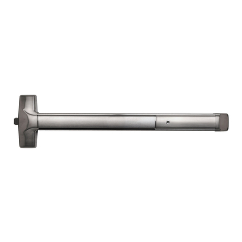
10 Series Advantex Wide Stile Rim Exit Devices.
40 Series Advantex Narrow Stile Rim Exit Devices.

Page 2of 17
Table of Contents
Component Page
Device Component Identification….…....…………………………..……………….3
Uninstalling Device ……………….………………………….……………..……………….4
Door Strikes……….…….…………….………………………………………..……………….8
Center Case.……..……..…….………………….……………………………………………11
Pushpad..……..…….…….……..…….………………………………………………………13
Filler Plate………..……..………………………………………………………………………14
Extrusion and Wrap…….……………………………………………………………….…14
End Caps.……….….……………………………………………………………………………15
Lubrication……...…………………….……………………………………………………….16

Page 3of 17
DEVICE COMPONENT IDENTIFICATION
10 Series device shown with hex dogging option, LHR and outside trim option installed.
Door Frame
Strike
Center Case with Cover
Pushpad Assembly
Outside Trim Function, 08D shown.
Filler Plate
with HD
End Cap
Door
Extrusion & Wrap
Hex Dogging Key

Page 4of 17
UNINSTALLING DEVICE
To facilitate maintenance procedures, the device must be removed from the door.
Verify the functionality of the device before removing any hardware. Look for any misaligned
components and missing or loose screws. Record the current status of the device, as this could
help plan a maintenance program that will keep the device working properly and extend its
service life. Use good quality tools with new tips to prevent damaging screws.
STEP 1. Open door to expose mounting screws for Strike, Center Case Cover and End Cap. Door
must be held in this position to allow removal of all necessary hardware.
99 Strike is mounted
with 3 screws.
94 Strike is mounted
with 2 screws.
98 Strike is mounted with 2
screws; the shield uses 4.
End cap is mounted with 2
screws.
(EC1 shown).
Center case cover is mounted
with 2 screws on strike side and 2
screws on pushpad side (10
Series shown).

Page 5of 17
STEP 2. Remove 4 screws used on center case cover and pull it away from device to access the
mount plate screws (2). Remove 2 screws used on end cap in order to access the end bracket
mounting screws (2). Although the surface finish is strong and durable, handle the parts with
care to avoid scratches or contamination from harsh chemicals during the service process.
STEP 3. Remove 2 screws on end bracket and slide it away from device, then remove 2 screws
on mount plate while holding the device horizontally and against door to keep it engaged after
removing all screws.
Center Case Cover
Mount Plate
End Bracket
End Cap
(4x) 6-32 x 3/8” PFHUMS
DTX #100162-106 FOR SS
(MULTIPLE FINISHES AVAILABLE)
(2x) ¼-20x1.0” PPH DTX #100980, or
(2x) #14 x 1.0” PPH SELF DRILLING #103276-63, or
(2x) #14 x 1.25” PPH WD SCREW #PP-5183-110
(2x) 10-32 x 5/16” PFHUMS
DTX #101632-2 FOR SS
(MULTIPLE FINISHES AVAILABLE)
(2x) ¼-20 x 1/4” PPHMS
DTX #101621-5
(2x) ¼-20 x 1/4” PPHMS
DTX #101621-5
(2x) ¼-20x1.0” PPH DTX #100980, or
(2x) #14 x 1.0” PPH SELF DRILLING #103276-63, or
(2x) #14 x 1.25” PPH WD SCREW #PP-5183-110

Page 6of 17
STEP 4. Push Pushpad and hold device with both hands. While keeping pushpad pushed, pull at
hinge side end away from door (1), swinging the device against center case mount plate to
disengage tabs and allowing device to pull free from mounting plate (2). Place device on a flat
surface covered with a clean, soft cloth to avoid scratches or surface contamination.
STEP 5. Uninstall mount plate removing screws shown below. These screws are also used to
hold Outside Trim; if installed, it must be supported while removing screws. There are 3
different screw options that can be used during installation depending on device model used.
NO NEED TO REMOVE BACKPLATE
(4x) #1/4 STAR LOCK
WASHER
DTX #PP-5067-25
(4x) ¼-20x1.0” PPH DTX #100980, or
(4x) #14 x 1.0” PPH SELF DRILLING #103276-63, or
(4x) #14 x 1.25” PPH WD SCREW #PP-5183-110
10 SERIES MOUNT PLATE
40 SERIES MOUNT PLATE
Door hinge side
(2)
(1)
Mount plate

Page 7of 17
STEP 6. Uninstall device components, position device on its back and slide out filler plate and
rub strip from housing. Filler plate may include wires; if so, these should be handled carefully to
avoid damaging electronic connections.
STEP 7. (SHOWN FOR REFERENCE ONLY) 4 cover screws that hold the pushpad assembly should
never be removed.
STEP 8. (SHOWN FOR REFERENCE ONLY) center case is attached to pushpad mechanism at
factory with screws and thread lock and SHOULD NEVER BE REMOVED.
FILLER PLATE
RUB STRIP
NEVER REMOVE THESE
(4X) 8-32 x 1/4” BTN CAP
TORX PLUS DTX #104637-2
PUSHPAD COVER
PUSHPAD MECHANISM
CENTER CASE
NEVER REMOVE THESE
(2X) 8-32 x ¼” PFH UNDERCUT
DTX #100156-104
CENTER CASE
PUSHPAD MECHANISM

Page 8of 17
STEP 9. (SHOWN FOR REFERENCE ONLY) This step concludes the disassembling of a 10/40
Advantex series rim exit device.
STRIKES –During maintenance, strikes do not need to be removed, may only
need adjustment
Door Strikes shall be checked periodically for any debris or foreign material that could
interfere with their primary function of keeping a door locked. Screws must be tightened and
excessive lubricant or rust should be removed. The Advantex 10 and 40 series exit devices can
be configured with 3 different door strikes.
OPTION 1. 99 Strike Kit DTX #100855-2.
Strike model 99 is surface mounted with 3 screws and shimmed as needed to allow
proper alignment with the latch of the device. The middle screw is installed after the strike has
been adjusted and tested; it will secure the strike’s position and prevent any further
movement. Kit includes all parts shown below; additional mount screws are included (not
shown) to accommodate varying door and frame construction.
(2X) #10 STAR LOCK WASHER
DTX #PP-5067-10
(2X) 10-32 x1/4” PPH
DTX #PP-5207-104
DTX #PP-5067-10
(2X) PUSHPAD END CAP ADV
DTX #104617-1
(MULTIPLE FINISHES AVAILABLE)
LATCH END
CHASSIS

Page 9of 17
OPTION 2. 98 strike kit DTX #100855-1.
Strike model 98 is a half mortise mounted with 2 screws and is shimmed as needed to
allow proper alignment with the latch of the device. It includes a shield that helps prevent
tampering and is typically used on glass doors. Kit includes all parts shown below; additional
mount screws are included (not shown) to accommodate varying door and frame construction.
DOOR FRAME
SHIM
STRIKE
LOCK SCREW
MOUNT SCREW
DOOR FRAME
SHIELD
STRIKE
MOUNT SCREW
MOUNT SCREW
SHIM

Page 10 of 17
OPTION 3. 94 strike kit DTX #102212-1.
Strike model 94 is mounted with 2 screws and is shimmed as needed to allow proper
alignment with the latch of the device. It is designed to be used on double-door applications
with one side inactive. Kit includes all parts shown below; additional mount screws are included
(not shown) to accommodate varying door construction.
SHIM
STRIKE
MOUNT SCREW
INACTIVE DOOR LEAF
INACTIVE DOOR LEAF
ACTIVE DOOR LEAF

Page 11 of 17
CENTER CASES
Advantex 10 and 40 Series exit devices can be built with either a Wide Stile Center Case
Cover (10 Series) or a Narrow Stile Center Case Cover (40 Series).
DTX #
MODEL DESCRIPTION
100196-X
COVER WIDE RIM
100311-X
COVER NARROW RIM
Advantex 10 and 40 Series exit devices can be built in a variety of configurations. There are 3
main models of center case assemblies that can be found in a pushpad assembly, depending on
the features that are required by the application.
OPTION 1. Center Case Subassembly: Standard model DTX #100698-X, used as follows:
DTX #
MODEL DESCRIPTION
100698-1
CENTER CASE ADV 40 LD/HD/CD/EA
100698-1W
CENTER CASE ADV 40 W LD/HD/CD
100698-2
CENTER CASE ADV 10 LD/HD/CD/EA
100698-2W
CENTER CASE ADV 10 W LD/HD/CD
100698-4
CENTER CASE ADV 10 ES/EI
100698-6
CENTER CASE ADV 40 ES/EI
DTX #100698-2 10 SERIES SHOWN
DTX #100196-X 10 SERIES SHOWN

Page 12 of 17
OPTION 2. Center Case Subassembly: EE OPTIONS DTX #104023-X, used as follows:
DTX #
MODEL DESCRIPTION
104023-2
CENTER CASE ADV 10 EE
104023-3
CENTER CASE ADV 40 EE
OPTION 3. Center Case Subassembly: LX/LXV OPTION DTX #103786-3, used as follows:
DTX #
MODEL DESCRIPTION
103786-1
CENTER CASE ADV 40 EA/ED/ER/LD/CD ETC. LX
103786-2
CENTER CASE ADV 10 EA/ER/LD/ ETC. LX
103786-3
CENTER CASE ADV 10 EE/LX
103786-4
CENTER CASE ADV 40 EE/LX
103786-5
CENTER CASE ADV 40 EA/ED/ER/LD/CD ETC. LXV
103786-6
CENTER CASE ADV 10 EA/ER/LD/ ETC. LXV
103786-7
CENTER CASE ADV 10 EE/LXV
103786-8
CENTER CASE ADV 40 EE/LXV
Advantex 10 and 40 Series devices are mounted to a door through the center case,
which is mounted to a specific plate attached with varying hardware, depending on door
construction and application requirements. A mount plate kit contains the installation
instructions and templates to mark and drill all necessary holes to attach a door strike and
mount plate. Device main installation hardware kit includes mount plate’s hardware.
DTX #104023-2 10 SERIES SHOWN
EE FEATURE PWA
EE/ FEATURE PWA
LX FEATURE SWITCH
DTX #103786-2 10 SERIES SHOWN

Page 13 of 17
PUSHPAD
Advantex 10 and 40 Series devices are available with pushpad assemblies of three (3)
different lengths (30”, 36” or 48”). Each pushpad assembly can also have a variety of
configurations, depending on the application of the device.
DTX #
LENGTH
CONFIGURATION
104610-X
30”
LD, CD, HD, EA, EI, ES, EB-W, ED, ER, EA-
EX, EX-ES, EX, EX-W, EXV, EXV-W, LX-ES, EX-
LX-ES, ER-EX-W, ER-EXV-W
36”
48”
104650-X
36”
EE Delayed Egress
48”
DTX #
MODEL DESCRIPTION
103806-1
BP2 RIM 98
103806-1W
BP2 RIM 98 W
103806-2
BP1 RIM 99
103806-2W
BP1 RIM 99 W
103806-3
BP2 RIM 99
103806-3W
BP2 RIM 99 W
103806-16
BP2 RIM 94
103806-16W
BP2 RIM 94 W
103806-17
BP1 RIM 94
103806-17W
BP1 RIM 94 W
10 SERIES MOUNT PLATE
40 SERIES MOUNT PLATE
ADDITIONAL SCREWS
REQ’D WHEN DOOR IS
HURRICANE RATED

Page 14 of 17
FILLER PLATE
Filler plates are held in place between the pushpad and the end cap; no screws or hooks
are needed to hold the filler plates in place. Like the pushpad, filler plates have a variety of
lengths and configurations depending on the application of the device.
DTX #
LENGTH
CONFIGURATION
24”
100711-X
30”
LD, CD, HD, EA, EI, ES, EB-W, ED, ER, EA-
EX, EX-ES, EX, EX-W, EXV, EXV-W, LX-ES, EX-
LX-ES, ER-EX-W, ER-EXV-W
36”
48”
EXTRUSION & WRAP
Extrusions and wraps come in a variety of lengths and finishes. The standard lengths are
the same as for the pushpad and filler plate. However, custom lengths are available depending
on the width of the door where the device is installed. The extrusion and wrap hold the body of
the device without screws; the wrap just slides into the extrusion.
END CAPS
DTX #
LENGTH
24”
101381-X
30”
36”
48”
DTX # 100711-X CD SHOWN

Page 15 of 17
There are two models of end caps for Advantex devices: the EC1 (ramped end cap) and
the EC2 (flush end cap). Each model has an additional FC (flex conduit) option. All end caps are
mounted with 2 screws into the end bracket.
OPTION 1. EC1 DTX #101642-X.
OPTION 2. EC1 FC DTX #102095-X.
OPTION 3. EC2 DTX #104304-X.
OPTION 4. EC2 FC DTX #104317-X.
DTX DASH #
FINISH DESCRIPTION
-1
BHMA POLISHED BRASS 605 FINISH
(US-3)
-2
BHMA BRUSHED BRASS 606 FINISH
(US-4)
-3
BHMA POLISHED BRONZE 611 FINISH
(US-9)
-4
BHMA BRUSHED BRONZE 612 FINISH
(US-10)
-6
BHMA POLISHED CHROME 625 FINISH
(US-26)
-7
BHMA BRUSHED CHROME 626 FINISH
(US-26D)
-8
BHMA POLISHED STAINLESS STEEL 629
FINISH (US-32)
-9
BHMA BRUSHED STAINLESS STEEL 630
FINISH (US-32D)
-10
UNFINISHED
-16
BLACK PAINTED BHMA 693
-17
DARK BRONZE PAINTED BHMA 695
-20
BHMA OIL RUBBED BRONZE 613
FINISH (US-10B)
-26
BHMA OIL RUBBED BRONZE 613
FINISH (US-10B)

Page 16 of 17
LUBRICATION
All Detex devices are delivered properly lubricated with a multipurpose synthetic
grease. It is strongly recommended that all mechanical parts and surfaces of the device be
periodically lubricated, inspected, and tested. Before applying lubrication:
1) Remove/Clean any foreign material from area to be lubricated.
2) Apply enough lubrication to assure penetration between moving parts.
3) Detex uses NS-10895-G from Syn-Tech. Spray lubricants may be used.
4) See diagram below for recommended points of lubrication.
Other manuals for Advantex 10 Series
1
This manual suits for next models
1
Table of contents
Other Detex Door Opening System manuals
Popular Door Opening System manuals by other brands

fadini
fadini APROLI 380 LB instruction manual

Langer & Laumann
Langer & Laumann Otis 6970 user manual

Assa Abloy
Assa Abloy NORTON RIXSON 5200 Series installation instructions

Freeman & Pardoe
Freeman & Pardoe BM3SE quick start guide

Von Duprin
Von Duprin Allegion 3327A Series Service manual

Lukas
Lukas HT 90 operating instructions