manuals.online logo
Brands
  1. Home
  2. •
  3. Brands
  4. •
  5. Detex
  6. •
  7. Door Opening System
  8. •
  9. Detex AO19 User manual

Detex AO19 User manual

Other manuals for AO19

2

Other Detex Door Opening System manuals

Detex Advantex RIM User manual

Detex

Detex Advantex RIM User manual

Detex EAX-300 Series User manual

Detex

Detex EAX-300 Series User manual

Detex AO19 User manual

Detex

Detex AO19 User manual

Detex Advantex 10 Series User manual

Detex

Detex Advantex 10 Series User manual

Detex AO19-1 User manual

Detex

Detex AO19-1 User manual

Detex AO19-2 User manual

Detex

Detex AO19-2 User manual

Detex Advantex RIM User manual

Detex

Detex Advantex RIM User manual

Popular Door Opening System manuals by other brands

Mobeye Call-Key MCK100 installation manual

Mobeye

Mobeye Call-Key MCK100 installation manual

SALICE Lapis Assembly instructions

SALICE

SALICE Lapis Assembly instructions

Cal-Royal N-F77CVR Installation instruction

Cal-Royal

Cal-Royal N-F77CVR Installation instruction

Scrigno OPEN1000 Assembly manual

Scrigno

Scrigno OPEN1000 Assembly manual

BFT WIND RMB 130B 200 installation manual

BFT

BFT WIND RMB 130B 200 installation manual

Alecto ADI-250 user manual

Alecto

Alecto ADI-250 user manual

Besam Swingmaster MP Installation, adjustment and maintenance instructions

Besam

Besam Swingmaster MP Installation, adjustment and maintenance instructions

Assa Abloy SARGENT 1431 Series instructions

Assa Abloy

Assa Abloy SARGENT 1431 Series instructions

GAL MOVFR Quick setup

GAL

GAL MOVFR Quick setup

Häfele Finetta T 70 VF manual

Häfele

Häfele Finetta T 70 VF manual

AGS D-PL Instructions for fitting, operating and maintenance

AGS

AGS D-PL Instructions for fitting, operating and maintenance

Stanley MA900ñ Installation and owner's manual

Stanley

Stanley MA900ñ Installation and owner's manual

WITTUR Hydra Plus UD300 Instruction handbook

WITTUR

WITTUR Hydra Plus UD300 Instruction handbook

Alutech TR-3019-230E-ICU Assembly and operation manual

Alutech

Alutech TR-3019-230E-ICU Assembly and operation manual

Pamex KT-INP35 Installation instruction

Pamex

Pamex KT-INP35 Installation instruction

MPC ATD ACTUATOR 50 ATD-313186 Operating and OPERATING AND INSTALLATION Manual

MPC

MPC ATD ACTUATOR 50 ATD-313186 Operating and OPERATING AND INSTALLATION Manual

Chamberlain T user guide

Chamberlain

Chamberlain T user guide

Dorma MUTO COMFORT M DORMOTION 50 Mounting instruction
Dorma

Dorma MUTO COMFORT M DORMOTION 50 Mounting instruction
manuals.online logo
manuals.online logoBrands
  • About & Mission
  • Contact us
  • Privacy Policy
  • Terms and Conditions

Copyright 2025 Manuals.Online. All Rights Reserved.

Quick Install Guide For Model AO19
Low Energy Automatic Door Operator
Push Type
July 3, 2008
P/N 103186
Parts Needed
1. Header Box/Cover
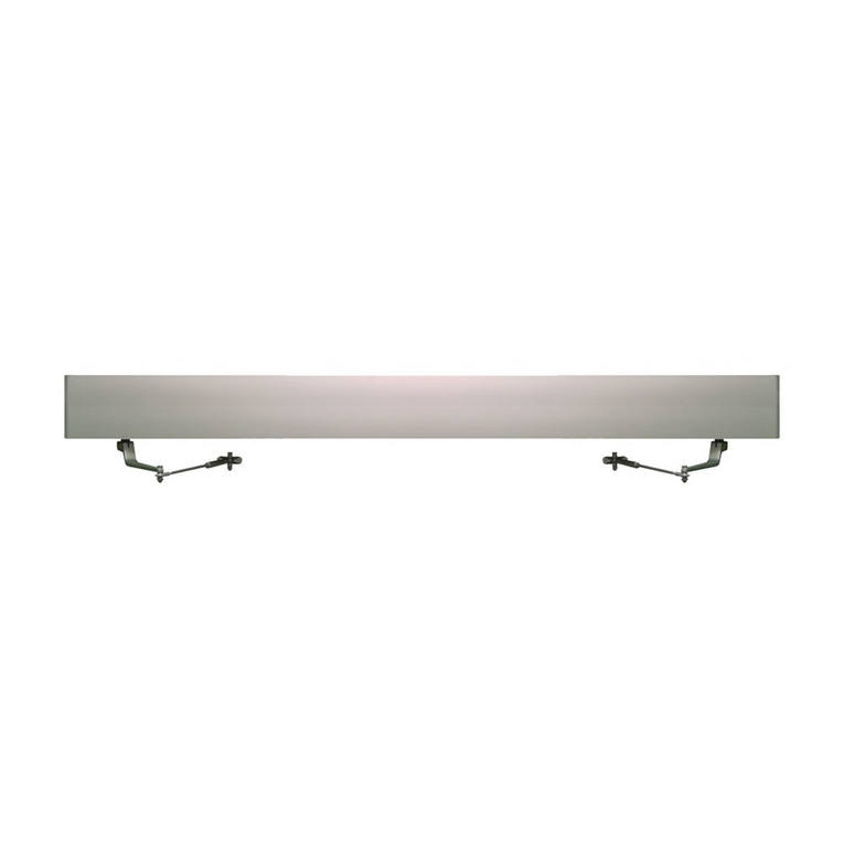
2. AO19 Operator
3. 3-Point Arm Assy – Push
4. Controller Module
Tools Required
1. Phillips Screwdriver
2. Vise Clamps
3. Ladder
4. Appropriate screws to
secure to wall
5. Safety Glasses
Cover
AO19 Low Energy
Automatic Door Operator
Controller Module
P/N 104792
3-Point Arm Assy.-Push
P/N 104798
INSTALLATION – PUSH MODEL
1. INSTALLATION PREPARATION
Locate Phillips screws inside at the top corners.
Remove these screws and separate the header
from the hanger plate
The hanger plate should be located 5/8" from the
outside edge of the hinge jam.
It should be level and flush with the bottom of the
header.
Secure hanger plate with vise clamps to the
header and drill 3/16" holes.
Fasten hanger plate.
2. INSTALLATION OF HANGER PLATE
3. PLACE OPERATOR ON HANGER PLATE
Lift the operator and lower into webs of the hanger plate. Ensure both top
and bottom are engaged.
Once seated, gently pull down until the unit is completely flush and secure
with screws on top corners.
Note: Secure to solid foundation or wall studs.
Pg. 1
Quick Install Guide For Model AO19
Low Energy Automatic Door Operator
Push Type
P/N 103186
Note: Refer to installation instructions
4. CONTROL / ARM INSTALLATION
PROP DOOR IN FULL OPEN POSITION
Remove control module from shipping box.
Secure the control module to header using Velcro provided.
Plug motor gear box assembly 110 power into control module.
Turn “open” and “back check” speed up to ensure the motor gear
box opens all the way. Turn 3-way toggle switch to “Hold Open”
position.
Once the motor gear box fully rotates to hold open position,
attach the arm onto the splined shaft so it is pointed at 60 – 70
degrees angle through the door.
Note: Once the arm is in place, you should not be able to push it
past the 60/70 degree mark. If you are able to push it past the mark,
turn the unit off, then turn “open” and “back check” speed up and
repeat instructions.
5. ARM AND FOOT PLACEMENT
The door foot will be located 16" center from the hinge side of
the door panel and will be level when the rod is inserted in
sleeve attachment to arm.
With the operator at full open, hold the steel rod next to the rod
connector at the end of the arm.
Cut the rod then attach door foot to door.
Place rod into connector with door in full open position.
Tighten set screws.
6. ARM POSITION FOR PUSH UNITS
After header is secure, activate unit and open door to 90
degrees.
Put the arm on so that the end is rotated beyond the edge
of the operator case.
Locate the door foot 16 ½” from the heel of the door.
Pg. 2
Note: Refer to installation instructions