DETRUM GAVIN-6C User manual

TABLE OF CONTENTS
Introduction..........................................................................................................1
Disclaimer ........................................................................................................1
Indications and Symbols for Safe Use.............................................................1
Installation Precautions....................................................................................1
Flying Precautions ...........................................................................................2
Product Description............................................................................................5
Box Contents ...................................................................................................5
Transmitter.......................................................................................................5
Specifications .............................................................................................5
Features......................................................................................................5
Names of Each Transmitter Control...........................................................7
Main Screen .............................................................................................10
Receiver.........................................................................................................11
Specifications ...........................................................................................11
Features....................................................................................................11
Receiver Connections ..............................................................................11
Basic Operation.................................................................................................13
Adjust the Stick Lever Tension.......................................................................13
Change the Location of Throttle Stick ...........................................................14
Turn on/off the Transmitter.............................................................................15
Binding...........................................................................................................16
Range Test.....................................................................................................17
Flight Mode ....................................................................................................17
Dual Rate (D/R) setting..................................................................................18
Model Parameter ...............................................................................................19
Servo Reverse [Rev Set] ...............................................................................19
End Point [End Point].....................................................................................20
Sub Trim [Sub Trim].......................................................................................21
Stick Curve [Stick Curve]...............................................................................21
Throttle Curve [THR Curve]...........................................................................23

Pitch Curve [PIT Curve] (Heli only)................................................................25
Throttle Hold [THR Hold] ...............................................................................26
Mix Set [Mix Set] (Airplane only) ...................................................................27
Delta Mixing [Delta Mix]............................................................................27
V-tail Mixing [V-tail Mix] ............................................................................29
Flaperon Mixing [Flaperon Mix]................................................................31
Throttle to Balance Mixing [THR▶BAL Mix]..............................................33
Veer to Elevator Mixing [Veer▶ELE].........................................................34
Swash Mixing [Swash Mix] (Heli only)...........................................................35
Servo Delay [Servo Delay] (Airplane/Heli only).............................................37
Channel Monitor................................................................................................38
Model Set............................................................................................................39
Select Model [Model] .....................................................................................39
Edit Model Name [Name]...............................................................................39
Select Model Type [Type] ..............................................................................40
Function Set [Func Set].................................................................................40
Trainer Set [Trainer Set] ................................................................................41
Fail Safe [Fail Safe] .......................................................................................43
Timer Set [Timer 1/2/3 Set]............................................................................45
Reset Model [Reset] ......................................................................................46
System Set.........................................................................................................48
Language [Language]....................................................................................48
Calibration [Calibration] .................................................................................48
Stick Mode [Stick Mode]................................................................................49
Key Volume [Key Volume] .............................................................................50
Key Tone [Key Tone]......................................................................................51
Back-light Brightness [Brightness].................................................................51
Contrast [Contrast].........................................................................................51
Back-light Time [Bright Off]............................................................................51
About Information [About]..............................................................................52

- 1 -
Introduction
Disclaimer
Thank you for purchasing this DETRUM product. This is a 2.4GHz digital
proportional R/C system with high performance. In order to make full use of the
features of this product and to safely enjoy your R/C activities, please read this
manual carefully before using. Please install and use this product in strict
accordance with the manual. The company assumes no liability or loss incurred
directly or indirectly from improper use, installation, or any modification of this
product.
Products shall be subject to any changes without additional notices.
This product is suitable for users experienced in operating model aircraft and
aged 14 years or older.
Please fly at a locally recognized model aircraft flying field.
Indications and Symbols for Safe Use
The following symbols used in this manual indicate the precautions regarding
possible danger which may occur following improper operation.
DANGER: Procedures, which if not properly followed, may lead to a
dangerous condition of death or serious injury.
WARNING: Procedures, which if not properly followed, may lead to a
possibility of death or serious injury.
CAUTION: Procedures, which if not properly followed, may lead to a
possibility of property damage, or a danger of injury.
Prohibited Mandatory
Installation Precautions
It is very important to properly install the R/C system on the model aircraft.

GAVIN-6C Instruction Manual
- 2 -
Please refer to the following instructions:
In order to protect the receiver, wrap the receiver with 10mm foam rubber,
and then fasten it with a rubber band or a Velcro strap.
The servos should be installed with rubber gaskets and brass eyelets to
isolate the vibration from the fuselage. When locking the screws, follow the
principle that the rubber gasket does not distort. If the locking is too tight, it
will reduce the vibration-proof performance.
When mounting a servo, make sure that the servo can rotate over its full
travel and check that the push-rods and servo arms do not bind or contact
each other.
When mounting a power switch, keep away from the engine's exhaust pipe
and any places with high vibration. And ensure that you can turn the switch
on/off without binding.
The two antennas of the receiver should be placed at 90 degrees to each
other. Do not place the two antennas twisted together or in parallel.
Flying Precautions
WARNING: Personal injury and property loss may be caused by improper
aircraft handling. Please operate strictly according to the following safety
instructions.
Flying Field and Conditions:
In order to protect the personal safety and their property, please do not fly at
the following places:
Near another radio control flying field
Near or above people
Near residential areas, schools, hospitals or other places where people
congregate
Near high-voltage lines, tall buildings, or communication facilities
Never fly on rainy day, thunder storm, when the wind is strong, and at night.
Always keep away from wet conditions.

GAVIN-6C Instruction Manual
- 3 -
This product is made of precision electronic components and mechanical
parts, please keep away from wet conditions, to prevent the components
damage from water and cause a failure which would lead to a crash.
Always keep away from hot conditions.
This product is made of precision electronic components and mechanical
parts, please keep away from hot conditions, to avoid distortion or damage.
Precautions before Flight:
Always make sure that all servos in the model work properly following the
transmitter stick movements prior to flight. And make sure that all switches
work properly as well.
Always check the remaining capacity of both the transmitter and receiver
batteries before each flying session prior to flight. Low battery capacity will
cause loss of control and a crash.
Always perform a range test before each flying session.
Always check the operation of each control surface before each flying session.
When using the trainer function, please check both the instructor and student
transmitters.
For safety reasons, always set fail safe functions before each flying session.
Especially set the throttle channel fail safe function.
Precautions during Flight:
Never grasp the transmitter antenna during flight. Otherwise, the transmitter
output power will reduce drastically.
Do not point the antenna directly toward the aircraft during flight. When
pointing the antenna directly, the transmitter output is the weakest. The
strong radio wave radiate from the side of the transmitter antenna.
Never turn on and off the power switch of transmitter during flight or while the
engine or motor is running.
Do not touch the engine, motor or other heating device or component during
and immediately after use. These devices or components may become hot
during use.

GAVIN-6C Instruction Manual
- 4 -
For safety, always fly the aircraft in visible range. Flying behind tall buildings
will not only lose sight of the aircraft, but also degrade the RF signal
performance.
Always return the transmitter setting screen to the initial main screen during
flight. Erroneous input during flight is very dangerous.
Precautions in Other Conditions
Never fly in the range check mode (test mode). In the range check mode, the
transmitter output power is greatly reduced, it may cause a crash.
When setting the transmitter during flight preparations, do not set it upright on
the ground. The transmitter may fall to the ground, the sticks may move and
the servos may rotate unexpectedly and cause injury.
Do not touch the receiver antenna directly by hands. Otherwise, the
components may be damaged by static, and this may cause a reduction in
transmission distance of the receiver.
Before turning on the transmitter, always make sure the transmitter throttle
stick and throttle trim are in the lowest position.
Always turn on the R/C system in proper sequence: turn on the transmitter
first, then turn on the receiver, and then turn on the engine or motor. Incorrect
sequence may cause loss of control and personal injury.
Always turn off the R/C system in proper sequence: turn off the engine or
motor first, then turn off the receiver, and then turn off the transmitter.
Incorrect sequence may cause loss of control and personal injury.

- 5 -
Product Description
Box Contents
GAVIN-6C Transmitter
DETRUM RXC7 Receiver
Bind Plug
Instruction Manual
USB Cable (optional)
Simulator Convertor (optional)
9g Servo *4pcs (optional)
NOTE: The set contents depend on the type of set.
Transmitter
Specifications
Parameters
GAVIN-6C Specifications
Coder
6-channel
Transmitting frequency
2.4GHz
Power supply
1.5V AA batteries *4pcs
Consuming current
Test mode: less than or equal to 120mA.
Operating mode: less than or equal to 230mA.
Output power
Test mode: 10mW. Operating mode: 100mW.
Output pulse
1050~1850ms (neutral 1500ms)
Features
It is suitable for airplane, helicopter, and multicopter (multirotor).
You can store a maximum of 30 aircraft models in the transmitter.
Adopting 2.4GHz direct sequence spread spectrum (DSSS) and multiple
frequency-hopping technology, the transmitter has strong anti-interference

GAVIN-6C Instruction Manual
- 6 -
performance.
The ergonomic design enables users to hold the transmitter easily.
The LCD display is designed with straightforward menu and intuitive graphical
interface. It is easy to understand and convenient to use.
This allows adjustment of the sticks lever tension, and there are four
selectable stick modes to meet different operating habits.
With a USB interface, it is easy to upgrade the transmitter firmware to the
latest program.
With fail safe function, it allows to set the positions that the servos move to in
the case of fail.
With trainer function, make it possible that a skilled instructor can teach a
student with flying skills.
With test mode function, it allows to check the environment interference and
the R/C system before each flying session.

GAVIN-6C Instruction Manual
- 7 -
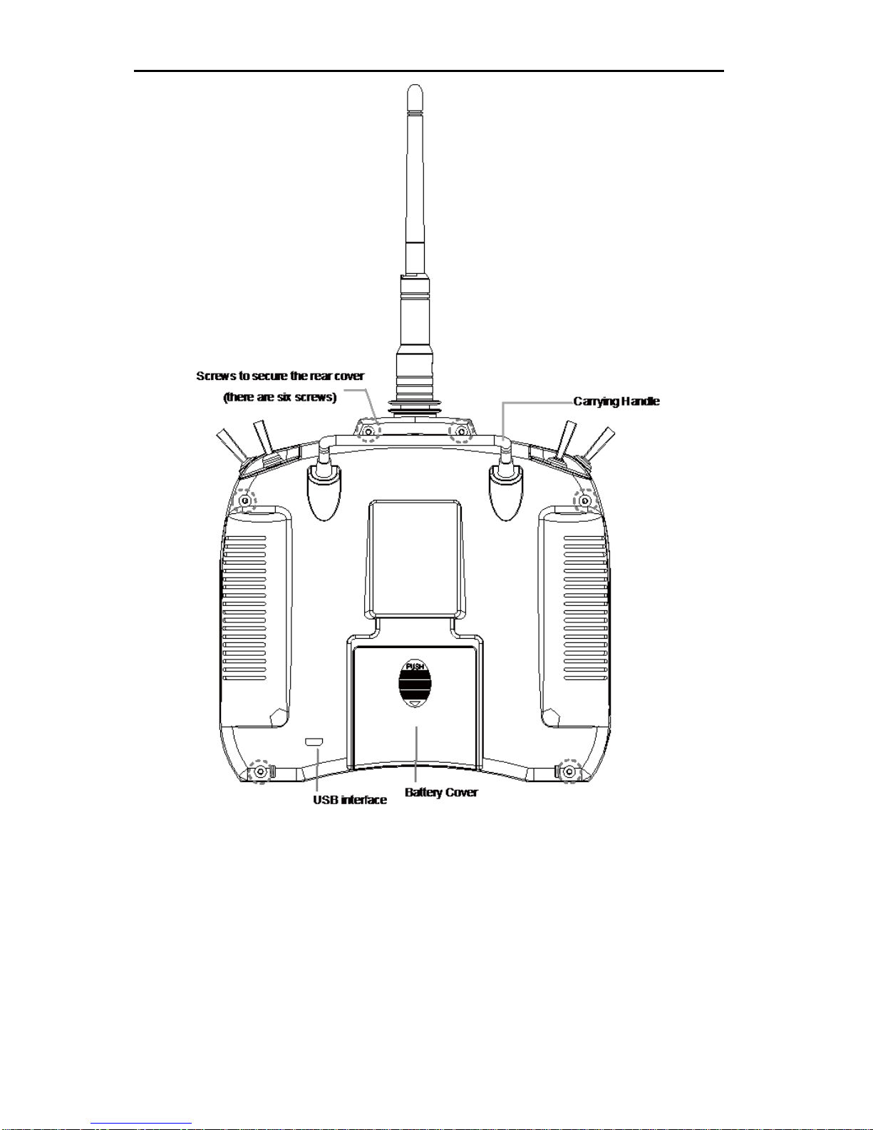
Names of Each Transmitter Control
NOTE: When the Stick Mode is set to MODE 1, the positions of sticks and
digital trims are shown in the figure. The positions are different depending on
the stick mode. For details, please refer to Stick Mode [Stick Mode] (Page
49).
Antenna
Digital Trim (elevator)
Switch (GEAR)
Switch (HOLD)
Digital Trim (rudder)
Elevator Stick
Rudder Stick
Trainer Connector
Exit Key (EXT)
Menu Selection Key
(UP, DOWN)
Neck Strap Attachment
Power Switch LCD Display
Changing Value Key
(R/+, L/-)
Enter Key (ENT)
Digital Trim (aileron)
Digital Trim (throttle)
Aileron Stick
Throttle Stick
Switch (FMOD)
Switch (FLAP)
Switch (TRAINER)
Status display LED
(under the Indicated position
GAVIN-6C Instruction Manual
- 8 -
Antenna
The strong radio wave radiate from the side of the transmitter antenna. Do not
point the antenna directly toward the aircraft during flight.
Carrying Handle
The carrying handle is designed for easily carrying and placing the
transmitter.

GAVIN-6C Instruction Manual
- 9 -
Power Switch
Push the switch upward to turn on the transmitter, push downward to turn off.
Neck Strap Attachment
For a long flight you can choose to use a neck strap for easy handing. The
neck strap attachment is on the neutral position, in order to get the best
balance for transmitter.
Switch
HOLD: 2 positions, alternate, short lever
FMOD: 3 positions, alternate, short lever
GEAR: 2 positions, alternate, short lever
FLAP: 2 positions, alternate, short lever
TRAINER: 2 positions, momentary, long lever
Generally, the throttle hold switch is set to HOLD, acrobatic flight switch is set
to FMOD, landing gear switch is set to GEAR, flap switch is set to FLAP.
Users can choose the above switches for specified functions according to
individual habits. For details, please see Function Set [Func Set] (Page 40).
Sticks
When the Stick Mode is set to MODE 1, the positions of sticks are shown in
the figure.
Digital Trims
This transmitter is equipped with four digital trims. Each time you press a trim
button, the trim position moves one step. You can always monitor trim
positions by referencing the LCD screen.
CAUTION: The trim positions you have set will be stored in memory and will
remain there even the transmitter powered off.
Keys
EXT: exit key, press this key to return to the previous menu.
UP: press this key to select the menu upward.
DOWN: press this key to select the menu downward.

GAVIN-6C Instruction Manual
- 10 -
ENT: enter key, press this key to enter the sub-menu or to confirm the
setting.
R/+: press this key to choose the value upward.
L/+: press this key to choose the value downward.
LCD
You can get the current status from the main screen, and set the parameters
from the function menu.
Simulator / Trainer Connector
It can be used as a simulator or trainer connector.
When it is used as a simulator connector, connect the transmitter and
computer with a dedicated control cable, and then carry out a simulated
flight on computer. In order to use this function, you need to equip with a
flight simulator and the matched attachment.
When it is used as a trainer connector, connect the instructor and student
transmitter with an optional trainer cable, and then a skilled instructor can
teach a student with flying skills.
USB interface
With a USB interface, it is easy to upgrade the transmitter firmware to the
latest program.
Main Screen
As shown in the figure, it is the main screen of the transmitter.
. .
. .
20%
00:00
00:00
1
2MODEL01
GAVIN-6C
NORM
00:05:57 80%
Digital Trim (rudder)
Timer (1, 2)
D/R Indicator
Product Model
Flight Mode
(Hold /Normal / Acrobatic)
Digital Trim (elevator)
Current Position
(based on the standard
servo movement)
Battery Indicator
System Timer
Model Type
Digital Trim (throttle)
Model Name
Digital Trim (aileron)
GAVIN-6C Instruction Manual
- 11 -
Note:
When the Stick Mode is set to MODE 1, the positions of trims are shown in
the figure. The positions are different depending on the stick mode. For
details, please refer to Stick Mode [Stick Mode] (Page 49).
For details about the flight modes, please refer to Flight Mode (Page 17).
Receiver
Specifications
Parameters
DETRUM RXC7 Specifications
Type
2.4GHz 7-channel
Sensitivity
-95dBm
Frequency interval
larger than or equal to 4MHz
Power supply
4.8~6V
Weight
10g
Size
39mm * 28.5mm * 14.5mm
Features
Adopting 2.4GHz direct sequence spread spectrum (DSSS) and multiple
frequency-hopping technology, the receiver has high sensitivity and strong
anti-interference performance.
Using diversity antenna, ensure that the receive signals are stable.
Multiple channels output the signals simultaneously, to enhance the
synchronized movement.
The receiver has a memory function for frequency and ID.
The receiver has the fail safe function.
The distance for signal control is more than 1000 meters.
Receiver Connections
The channels of DETRUM RXC7 receiver are labeled with names, as shown in
the following figure.

GAVIN-6C Instruction Manual
- 12 -
When connecting the servo to the channel connector, please note the line
sequence. Each connector has 3 pins, one of the pins near the front panel is the
signal end, and the remaining two pins are the positive and negative.
If the connectors become detached while flying, there will be a risk of
uncontrolled operation. Please securely insert all of the connectors as far as
they will go.
The two antennas of the receiver should be placed at 90 degrees to each
other. Do not place the two antennas twisted together or in parallel.
BIND
AUX2
AUX1
GEAR
RUDD
THRO
ELEV
AILE
Aileron channel
Elevator channel
Throttle channel
Rudder channel
Gear channel
Auxiliary channel
Auxiliary channel
Bind plug
(This is used during the bind procedure)
- 13 -
Basic Operation
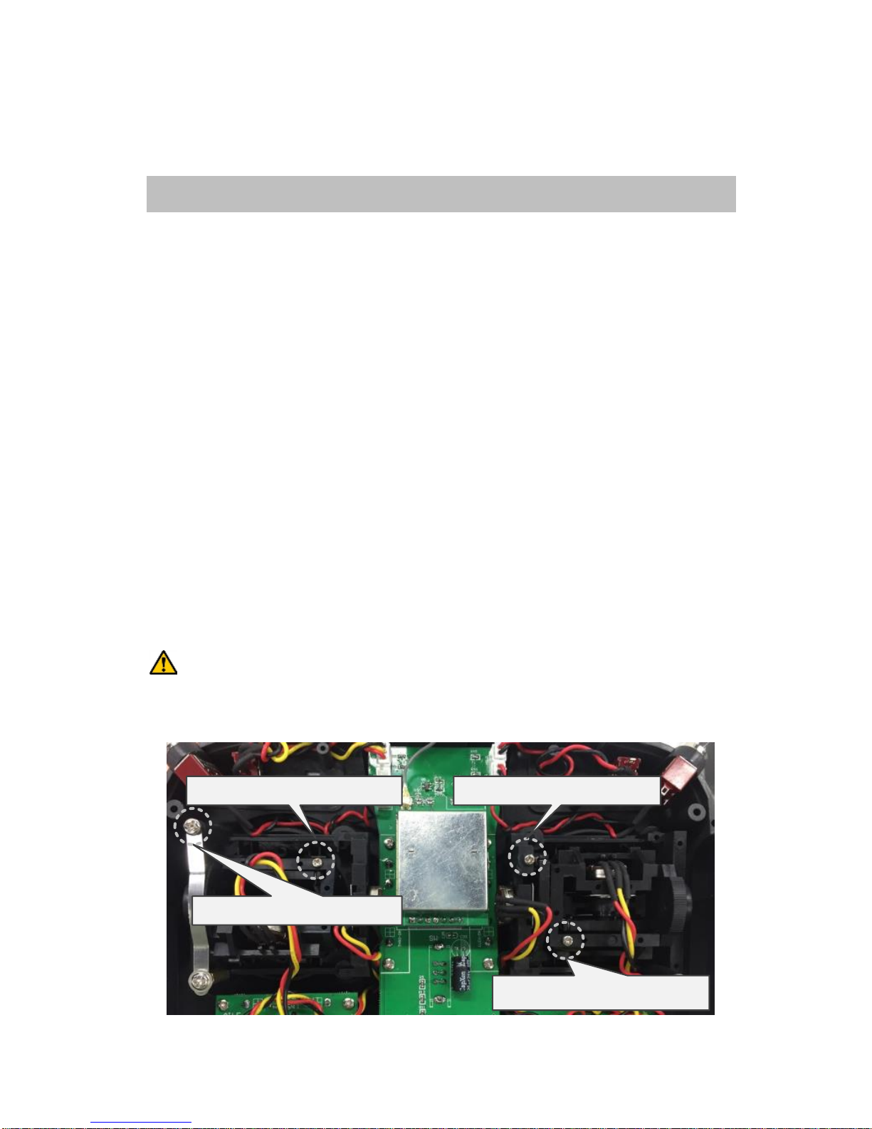
Adjust the Stick Lever Tension
This allows adjustment of the stick lever tension to meet different operating
habits.
Tools: Phillips screwdriver, ESD wrist strap or ESD gloves.
Conditions: Before operating, please wear an ESD wrist strap or ESD gloves.
Steps:
1. Open the battery cover, and remove the batteries.
2. Remove the six screws on the rear cover with a Phillips screwdriver.
3. Open the rear cover and remove the wirings between the PCB and rear
cover.
The wirings: a connection between the battery pack and the interface marked
with J1 on PCB, a connection between TRAINER switch and the interface
marked with TRAINER on PCB, a connection between USB interface and the
interface marked with USB on PCB.
CAUTION: Please gently ease off the transmitter's rear cover, to avoid
breaking the wirings.
Screw for spring adjustment Screw for spring adjustment
Screw for spring adjustment
Screw for spring adjustment

GAVIN-6C Instruction Manual
- 14 -
4. Use a Phillips screwdriver to adjust the spring strength as you prefer by
turning the screw of the stick you want to adjust. Turning the screw clockwise
increases the tension, counter clockwise to loosen.
CAUTION: Do not loosen the screw too much, the stick may not operate.
5. Connect the wirings between the PCB and rear cover, close the rear cover,
and then tighten the six screws on the rear cover.
6. Install the batteries and the battery cover.
Change the Location of Throttle Stick
If you want to change the throttle stick from right-hand to left-hand, or change
from left-hand to right-hand, it is need to change the location of the throttle stick,
and then change the stick mode. The following is the method for changing the
location of the throttle stick.
Tools: Phillips screwdriver, ESD wrist strap or ESD gloves.
Conditions: Before operating, please wear an ESD wrist strap or ESD gloves.
Steps:
1. Open the battery cover, and remove the batteries.
2. Remove the six screws on the rear cover with a Phillips screwdriver.
3. Open the rear cover and remove the wirings between the PCB and rear
cover.
The wirings: a connection between the battery pack and the interface marked
with J1 on PCB, a connection between TRAINER switch and the interface
marked with TRAINER on PCB, a connection between USB interface and the
interface marked with USB on PCB.
CAUTION: Please gently ease off the transmitter's rear cover, to avoid
breaking the wirings.
4. Remove the eight screws fixed the sticks on the front cover with a Phillips
screwdriver.

GAVIN-6C Instruction Manual
- 15 -
5. Remove the wirings between the sticks and PCB.
One stick is connected with two interfaces marked with AILE and THRO on
PCB, the other stick is connected with two interfaces marked with ELEV and
RUDD on PCB. Please remember the original connection before removing
the wirings.
6. Take out the two sticks and exchange the location, and tighten the eight
screws on front cover.
7. Reconnect the wirings between the sticks and PCB.
8. Connect the wirings between the PCB and rear cover, close the rear cover,
and then tighten the six screws on the rear cover.
9. Install the batteries and the battery cover.
NOTE: After changing the location of throttle stick and elevator stick, please
change the stick mode. For details, please refer to Stick Mode [Stick Mode]
(Page 49).
Turn on/off the Transmitter
Turn on the transmitter:
1. Move the throttle stick to the lowest position before turning on the power
switch.
2. Push the power switch upward to turn on the transmitter.
After power on, the LCD displays as the following figure. The transmitter's
LED indicator stays illuminated at the same time. Wait for about 2 seconds,

GAVIN-6C Instruction Manual
- 16 -
the LCD will enter the main screen.
If the throttle stick is not at the lowest position, after turning on the power
switch, the LCD will prompt "THR is not reset!". Lower throttle stick to the
lowest position, the information will disappear and the LCD will enter the main
screen.
Turn off the transmitter:
1. Turn off the power switch, the transmitter shut down at once.
Binding
In order for the transmitter and receiver to communicate, it is essential to pair or
bind them together. When you use the R/C system first time or change a
transmitter or receiver, this procedure is necessary.
Before binding, Lower throttle to the lowest position and make sure the
transmitter is powered off. Place the transmitter and the receiver close to each
other within a distance of about one meter.
Steps:
1. Insert the bind plug into the BIND port of the receiver.
2. Turn on the receiver. The receiver's red LED will flash slowly when receiver is
ready to bind.
3. While pulling and holding the TRAINER switch of transmitter, turn on the
transmitter. The system begins to bind.
4. Once receiver's green LED stays illuminated, this indicates the receiver is
bound to the transmitter. Release the TRAINER switch.
5. Remove the bind plug from the receiver. Turn off the transmitter and receiver.

GAVIN-6C Instruction Manual
- 17 -
Range Test
It is extremely important to perform a range check before each flying session.
This enables you to ensure that each function is working as it should be.
GAVIN-6C transmitter allows you to reduce its power output and access the test
mode. Then you can detect interference from environment and perform a range
check.
Steps:
1. Lower throttle to the lowest position and make sure the transmitter is powered
off.
2. While pressing ENT key, turn on the transmitter, the transmitter will access
the test mode.
The LCD will display as the following figure, and the transmitter's LED
indicator will flash on test mode.
You can exit the test mode by pressing EXT key.
Test mode on
2. With the test mode on, walk away from the model while simultaneously
operating the controls. Have an assistant stand by the model to confirm that
all controls are completely and correctly operational. You should be able to
walk approximately 30~50 paces from the model without losing control.
WARNING: Never fly in range check mode (test mode).
Flight Mode
The flight mode function allows switching between various aircraft flight
characteristics (flight mode) using a switch. The flight modes which can be
selected are various with model type.

GAVIN-6C Instruction Manual
- 18 -
Airplane / multicopter flight mode: NORM (normal) and HLD (hold).
Helicopter flight mode: NORM (normal), HLD (hold), and ACR (acrobatic).
It is possible to activate these flight modes by the throttle hold switch and
acrobatic flight switch:
The default throttle hold switch is HOLD. Users can modify it (please see
Function Set [Func Set] (Page 40)). Push the HOLD switch to the top, the
aircraft model will switch to NORM flight mode. Pull the HOLD switch to the
bottom, the aircraft model will switch to HLD flight mode.
Acrobatic flight function is only for the helicopter. The default acrobatic flight
switch is FMOD. Users can modify it (please see Function Set [Func Set]
(Page 40)). Push the FMOD switch to the top or middle, the aircraft model will
switch to NORM flight mode. Pull the FMOD switch to the bottom, the aircraft
model will switch to ACR flight mode.
Dual Rate (D/R) setting
This function switches aileron, elevator, and rudder control surfaces between
different control surface angles and curves, using the dual rate (D/R) switches.
Generally, different rates are required for different types of flying. For example,
low rate (smaller control surface angles) is required for flying at high speeds
whereby the model's response becomes more sensitive. On the other hand, high
rate might be required for flying slower aggressive acrobatic maneuvers such as
hovering thereby the model may not be as sensitive.
Setting Method:
1. Choose the switches for AIL D/R, ELE D/R, and RUD D/R functions.
The default values for AIL D/R, ELE D/R, and RUD D/R functions are OFF.
Users can choose from any of the switches (HOLD, FMOD, GEAR, and FLAP)
on the transmitter. The steps for setting the switches are described in
Function Set [Func Set] (Page 40).
You can select the same switch for aileron, elevator, and rudder control
surfaces, and can also select different switches for each control surface.
2. Put the switch to the up or down position for a high or low rate.
The high rate is 100%, and the low rate is 60%.
Table of contents
Other DETRUM Transmitter manuals

Popular Transmitter manuals by other brands

REL
REL 518-D instruction manual

Allmatic
Allmatic B.RO2 WALL quick start guide

Siemens
Siemens SITRANS L Series Compact operating instructions

Hallicrafters
Hallicrafters HT-46 Operating and service instructions

Siemens
Siemens SITRANS L Series operating instructions

Macurco
Macurco TracXP TXP-WTA instruction manual


