Votronic 5543 User manual

Tank Electrode 12-24 K Tank Height 12 - 24 cm, 12 V and 24 V Order-No. 5543
Tank Electrode 15-50 K Tank Height 15 - 50 cm, 12 V and 24 V Order-No. 5545
According to Drinking Water Ordinance DIN 2001-2
The tank transmitter had been designed for precise level measuring of fresh water tanks, sewage water tanks
and feces tanks of plastic and metal material in campers, caravans and boats.
Measurement of the level is effected fully-automatically without mechanically moving parts according to the
capacitive method of measurement, and it is transferred to the display unit via a three-core cable.
The electronic system is completely sealed. Thus, it is extremely robust and insensitive to soiling.
Tank measuring sensor, suitable and required for VOTRONIC tank displays, 1 piece per tank:
Tank Display Units: Order No. 12 V Order No. 24 V
•Fresh Water Tank Display S 5311 5311
•Sewage Water Tank Display S 5313 5313
•Feces Tank Display S 5315 5315
•Info Panel Pro 5330 6330
•Votronic VBS 2 Bus System All Types All Types
•Votronic VPC System All Types All Types
•Previous Votronic tank displays since 1987 All Types All Types
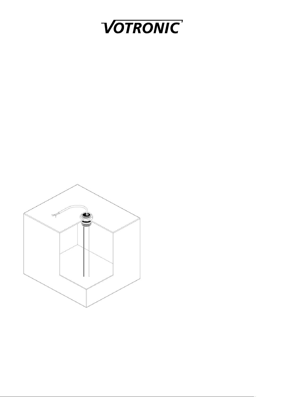
For remote level measurement, the tank electrode
is installed directly at the tank. It is suitable for:
•Fresh water (if applicable, please observe the
Guidelines for Drinking-Water Quality DIN
2001-2)
•Sewage water, grey water
•Feces sewage water
•Plastic tanks, any material
•Metal tanks (aluminium, steel, stainless steel,
etc.)
•Adjustable to tank heights:
12 to 24 cm or 15 cm to 50 cm.
Functioning:
The level in the tank is measured capacitively. The
insulated stick (probe) and the surrounding water
form a kind of "capacitor", the size of which is
growing with the level, and which is measured by
the electronic system. The contact to the water as
"antipole" is effected by a stainless steel stick.
Brief Instruction:
1. Produce a mounting hole at the tank with a diameter of 38 mm or thread PG29.
2. Determine the kind of installation, inside or outside the tank, and measure the tank height.
3. Cut both measuring sticks to the desired length (observe a clearance of 10 - 20 mm between sticks and tank
bottom).
4. Reinsert the insulating cap on the insulated stick (observe the tightness).
5. Install the tank transmitter inside or outside using the delivered packing ring.
6. Set the measured water depth at the scale.
7. Produce the electrical connection to the display unit.
8. Ready for start-up.

- 2 -
Preliminary Installation:
The tank electrode is designed for vertical installation from the tank top.
In contrast to sewage water and feces tanks (deposit), an installation at the lower side of the tank is also possible.
The tank electrode should be placed at the topmost location and in the tank centre.
Mounting hole, diameter 38 mm, or thread PG29.
Depending on the local conditions (available space above the tank, cutout of the intermediate floor, tank height etc.), the
tank transmitter can be installed at the tank inside or outside (for the short type tank electrode 12-24 K is for best results, if
possible, the installation outside recommended):
Installation inside Installation outside
After that, the two stick probes must be cut to identical length (metal saw, strong side cutter, bolt cutter).
It is important, that a clearance of at least 10 - 20 mm is left between tank bottom and probe ends (deposit, up-and-down
movement of the tank bottom and of the tank top during driving etc.)
Burr the sticks, and reinsert the insulating cap on the stick probe being insulated by the plastic pipe.
A thorough sealing between the insulating cap and the plastic pipe is decisive for proper operation of the tank electrode!
Set the adjuster tank height "FULL" 100 %:
Example: The scale
indicates
the value 18 cm
as adjusted
Tank Height

- 3 -
Configuration of Connections:
Colour Connection No. Tank Display Function recommended Cable Cross-Section
white 5 = Tank +(Plus) + Operating Voltage, from Display Unit Connection 50.5 - 1 mm²
green 4 = Tank Signal Measuring Signal to Display Unit Connection 4, 0…2.2 V 0.5 - 1 mm²
brown 1 = Battery -- Operating Voltage (common, minus) or Body Ground, 10.5 - 1 mm²
The tank electrode K is protected against any kind of reverse battery. It is recommendable to use connection cables of
different colours to avoid malfunctions due to mixed up connections.
As soon as the display unit has been installed according to the operating manual, the battery can be connected.
Start-up and Adjustment:
The adjuster at the upper side of the tank electrode is used to adjust the tank height to 100 % "FULL" at the display:
Insert a folding rule into the mounting hole of the tank to measure the exact tank depth (inside width), and set the adjuster
for the "water depth" to this value. The adjustment procedure is completed.
The functions of the display can now be simulated with several water levels in the tank (or in a bucket being filled with
water) or by withdrawing the tank electrode out of the full tank (or bucket).
Fine adjustment of the set water depth can be corrected or changed at any time with full tank.
Final Installation:
The delivered packing washer is placed between tank and casing flange. Screw the tank transmitter in place using the
coupling ring.
In case of underfloor installation of the tank, the adjuster must be protected with a permanently elastic sealant against
aggressive environmental influences (de-icing salt etc.).
Tips and Tricks:
No reaction of display:
a. Cable 4= Tank Signal Withdraw connector by way of trial and direct it to connection "5":
The display should increase to 100 % ! Otherwise:
b. Battery connection or fuse defective check!
c. Cable 5 = Tank Plus interrupted check!
d. Cable 4 = Tank Signal: Short-circuit to ground check!
Constant display of 100 % on the display unit:
a. Cable 4 = Tank Signal Withdraw it and direct it to ground: Display must be empty!
b. Cable 1 = Battery Minus / Ground is interrupted or does not have any contact due to paint residues at the bodycheck!
c. The insulated stick probe is contacting water: The silicone cap is leaky or dropped-off, the plastic pipe is damaged
check!
Indication Errors:
a. Intense soiling and furring of the insulated stick probe by stuck solids in the sewage water tank and feces tank
Rinse tank (no seawater), clean it if required !

- 4 -
Safety Regulations and Appropriate Application:
The tank measuring sensor has been designed according to the valid safety regulations.
Application is only allowed, if the unit is in technically faultless condition, with protected board battery
voltage of the indicated value and only for measurement of water or hydrous media.
•Never use the unit at locations where the risk of gas or dust explosion exists!
•The unit is to be disconnected from any connection prior to execution of electrically welding or work on
the electric system.
•Cables are always to be laid in such a way that damage is excluded. Observe to fasten them tightly.
•Never lay 12 V (24 V) cables and 230 V mains supply cables into the same cable conduit (empty conduit).
•Check live cables or leads periodically for insulation faults, points of break or loosened connections.
Occurring defects must be remedied immediately.
•If the user is not able to draw from the manual, which characteristic values are valid for a unit or which
regulations are to be observed, a specialist is to be consulted.
•The user/buyer is obliged to observe any construction and safety regulations.
•The unit is not equipped with parts, which can be replaced by the user.
•The warranty period is 24 months from the purchase date (against presentation of the sales slip or
invoice).
•The warranty will be void in case of any inappropriate utilisation of the unit, if it is used beyond the
technical specification, in case of improper operation or external intervention. We do not assume any
liability for any damage resulting hereof. The liability exclusion is extended to any service being executed
by third, which has not been ordered by us in writing. Service is to be effected exclusively by VOTRONIC
D-36341 Lauterbach.
Declaration of Conformity:
According to the stipulations of the regulations 2006/95/EG, 2004/108/EG, 95/54/EG this product
corresponds to the following standards or standardized documents:
EN55014; EN55022 B; DIN14685; DIN40839-1; EN61000-4-2; EN61000-4-3; EN 61000-4-4.
Disposal of
the product
in the
household waste
is not
allowed.
The product
conforms to RoHS.
Thus, it complies
with the directives for Reduction of
Hazardous
Substances in Electrical and
Electronic Equipment.
Technical Data:
Operating Voltage: 12 V-/24 V-DC Battery voltage (of the display)
Operating Voltage Range: 7...32 V
Current Consumption: 4...7 mA
Signal Output 0...100 %:0...2.2 V,
Measuring Method: capacitive, suitable for short-time and continuous operation
Tank Height, adjustable: 12…24 cm, 15…50 cm
Mounting Hole: 38 mm or thread PG 29
Flange Diameter: 46.5 mm
Length Connection Cable: 75 cm
Subject to misprints, errors and technical modification without notice.
All rights reserved, particularly the right of reproduction. Copyright VOTRONIC 12/14.
Made in Germany by VOTRONIC Electronic-Systeme GmbH & Co. KG, Johann-Friedrich-Diehm-Str. 10, 36341 Lauterbach/GERMANY
Phone: +49 (0)6641/91173-0 Fax: +49 (0)6641 / 91173-20 E-mail: info@votronic.de Internet: www.votronic.de
Delivery Scope:
•Tank Electrode 12-24 K or 15-50 K
•Coupling Ring PG 29
•Packing Washer
•
Mounting Instructions
This manual suits for next models
1
Table of contents
Popular Transmitter manuals by other brands

BWI Eagle
BWI Eagle AIR-EAGLE FM2 43-1150-120VAC Product information bulletin

Emerson
Emerson Rosemount Wireless Permasense WT210 quick start guide

Johnson Controls
Johnson Controls CD-W00-00-0 installation instructions

Massoth
Massoth 8131901 manual

Ramsey Electronics
Ramsey Electronics PX50 user guide

Sennheiser
Sennheiser BT T100 user manual