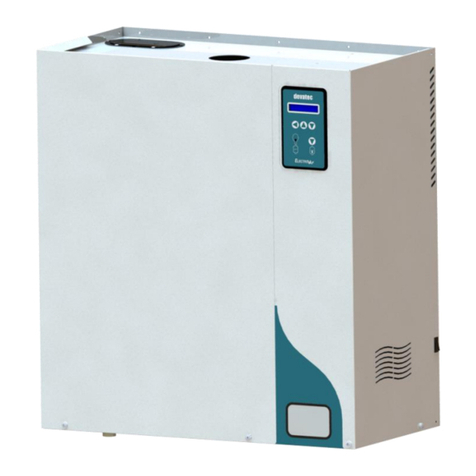
Devatec ElectroVap MC Series Installation instructions manual

ElectroVap® HUMIDIFIERS
KIT MC Series
Instruction & Operation
Manual

ELECTROVAP® KIT MC
2

ELECTROVAP® KIT MC
3
Sommaire
1. SAFETY INSTRUCTIONS 4
1.1 INTRODUCTION 4
1.2 IMPORTANT REMARKS 5
1.3 DECLARATION OF CONFORMITY 6
1.4 ROHS DECLARATION 6
2. PRODUCT PRESENTATION 7
2.1 CHARACTERISTICS 7
2.2 SIZE 8
2.3 HUMIDIFIER COMPONENT PARTS 9
2.4 IMPORTANT INSTRUCTIONS 10
INSTALLATION 13
3.1 PROCEDURE 13
3.2 WATER SUPPLY 15
3.3 DISPERSION TUBE POSITIONING 16
3.4 STEAM OUTLET 20
3.5 CONDENSATE DRAINING WITH SIPHON 21
3.6 DRAIN HOSE CONNECTION 22
3.7 ELECTRICAL CONNECTIONS 24
3.8 CONTROLS SIGNAL CONNECTION 26
COMMISSIONING 36
MAINTENANCE 37
5.1 GENERAL INFORMATION 37
5.2 STEAM CYLINDER CLEANING 38
5.3 CYLINDER REPLACEMENT METHOD 39
5.4 CYLINDER CLEANING METHOD 39
5.5 DRAIN VALVE 40
5.6 WATER INLET VALVE 41
SPARE PARTS 42
6.1 HYDRAULIC PART 42
6.2 WATER INLET VALVE 44
6.3 DRAINING CIRCUIT 44
6.4 ELECTRICAL PART 45

ELECTROVAP® KIT MC
4
1. SAFETY INSTRUCTIONS
1.1 INTRODUCTION
You recently purchased the ElectroVap® ELMC, and we hope you enjoy this product. Thank you for the
trust you place in us. The safety instructions contained in this manual are intended for specialized,
qualified, and authorized personnel.
To get the best results from the humidifier, we recommend to:
• Read carefully the assembly and installation instructions in this manual.
• Keep this manual in a safe place for future reference.
• Transmit this manual in case of sale or transfer of the device, in order to guarantee the transmission
of information about it.
SAFETY WARNINGS AND SYMBOLS USED IN THE MANUAL
Danger! Caution.
General safety instruction, whose violation could lead to malfunctions and / or bodily harm to
person and / or property damage.
Danger! High voltage.
There are highvoltagesinside the device or one ofits components, the negligence of this warning
can lead to serious bodily injury or death to people and / or significant material malfunctions.
Danger! High temperature.
The ElectroVap® ELMC uses steam during the operation and therefore surfaces and pipe-work
become very hot. Ensure that equipment not sustaining high temperatures is kept away.
Electrostatic hazard.
The components of the device may be subject to deterioration as they are very sensitive to
electrostatic discharge.
Möbius strip.
Some components of the device are recyclable, the user is responsible for the removal of these.
Follow the recycling recommendations adapted to the materials according to the geographical
area.
• If your package is damaged or missing, please make a complaint to your carrier with a receipt
acknowledgment letter within 24 hours and make a declaration to your Devatec agent.
• Pictures, graphics, and values may be subject to technical changes without notice.
• Keep this instruction manual carefully, and if you have any questions that are not answered in this
manual, do not hesitate to contact us, or consult your Devatec agent.
Our team will be pleased to be of assistance!

ELECTROVAP® KIT MC
5
1.2 IMPORTANT REMARKS
GENERAL
This manual is a translation of the original French version. This manual contains all the
details concerning the commissioning, operation, and maintenance of the device.
Maintenance, service, repairs, as well as the study of the risks and dangers associated
with these operations must be carried out by qualified, competent, and authorized
personnel.
- Make sure that all risks or dangers are defined beforehand by an authorized person,
especially for works-at-height.
- We also recommend installing a security perimeter.
- Make sure that the power supply is switched off before performing maintenance.
- Please screw periodically all the connection terminals of the power cable.
INTENDED USE
This device is manufactured by Devatec is intended solely for humidification purposes,
in air treatment station or in ambiance. The user undertakes to use it according to the
safety instructions given in this manual.
Improper use could result in serious hazards and damages to the user, third parties and
materials.
STORAGE &
MAINTENANCE
The device must be stored in a dry, frost-free place, protected from shocks and
vibrations. Maintenance must be carried out by at least two people or suitable lifting
equipment.
WATER
Steam humidifiers can be used with potable, demineralized, or softened water. It is
absolutely forbidden to inject a chemical into the hydraulic system. Make sure that the
water supply pressure does not exceed 6 bar. Always be careful that the installation
meets local standards.
ELECTRICITY
The user ensures that electrical installation will be carried out by an authorized
technician in this field. The installer must provide the correct cable section as well as
the magnethermic circuit breaker protection.
WARRANTY
Devatec guarantees that its devices are one (1) year warranty.
Devatec’s liability will be limited exclusively to Devatec’s repair or replacement of the
part or product, excluding labor, disassembly, or installation costs. Devatec may also
decide to refund the purchase price of the product or part of it, at its discretion. The
non-compliance of these above recommendations, additional mounting and / or
transformation with components other than those provided with the device or any use
other than what is explicitly stated, shall be considered as not in compliance with the
prescriptions, and will invalidate the warranty.
LIABILITY
Devatec shall be not made liable for the consequences of incorrect installation,
improper use of the devices and/or their components.
We are committed to provide you the most complete manual, although, in the air
treatment field, variations are so common that the information found in this document
may be subject to changes without notice.

ELECTROVAP® KIT MC
6
1.3 DECLARATION OF CONFORMITY
The devices identified by serial numbers between 60 000 and 69 999, meets the requirements of
the following European Directives:
2014/30/UE
2014/35/UE
DEVICE TYPE
Humidifier
MODEL NAME
KIT MC
MANUFACTURER
Devatec
185 Boulevard des Frères Rousseau
76550 Offranville - FRANCE
We the undersigned, hereby declare that the equipment specified above conforms to the above
Directive(s) and Standard(s). Valid for units with serial number starting from n° 60 001
FRAMBOT Jean-François
General Manager
05/01/2021
1.4 ROHS DECLARATION
Devatec,
Confirms that the ElectroVap® KIT MC humidifier is manufactured in compliance with the following
European regulations:
2011/65/UE
This guideline regulates, after July 1st 2006, the use of mercury, cadmium, lead (soldering processes),
chrome VI as well as PBB and PBDE.
MINFRAY Jean-Marie
R&D Engineer
05/01/2021

ELECTROVAP® KIT MC
7
2. PRODUCT PRESENTATION
2.1 CHARACTERISTICS
The KIT MC humidifier is an electric humidifier, designed for air humidification in air handling unit.
Standard delivery includes:
1. Steam humidifier
2. Technical documentation
3. 3 hose clamps (2 for the steam hose and 1 for the drain hose)
ACCESSORIES (Not supplied)
•Stainless steel steam dispersion tubes
•ExpressPack®
•Steam and condensate hose
•High Limit Humidistat
•Stainless steel braided hose in 3/4" FF (with
gaskets) for connection to water network.
•Drain hose
•Remote information board
•Filling cup extension
•Transformer 2x115V/2x12V/50VA
•Transformer 380-690V/115-230V/100VA
•Additional cooling kit
•Mounting bracket
•Collecting water tank
•Bluetooth kit for mobile application
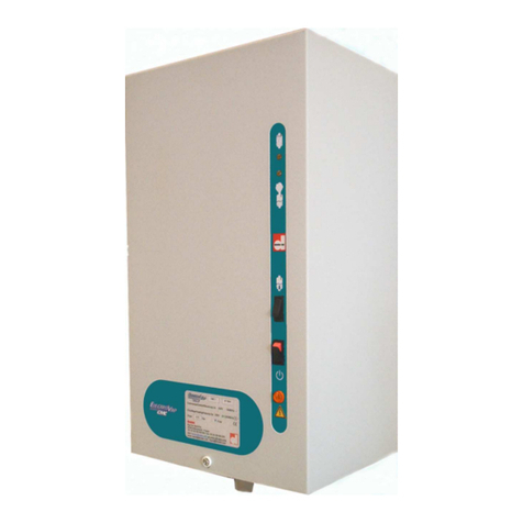
Fig. 2-1. Humidifier

ELECTROVAP® KIT MC
8
2.2 SIZE
KIT MC
5-15
KIT MC
20-30
KIT MC
40-60
Number of steam outputs
1
1
2
Dimension (mm)
A
305
305
710
B
453
605
605
C
270
270
270
D
191
191
191
E
480
632
632
F
30
30
30
G
146
146
146
H
x
x
305
I
178.5
178.5
141.5
J
x
x
345
Condensate outlet diameter
Ø 25
Ø 25
2 x Ø 25
Steam output diameter
Ø 25 or 40
Ø 25 or 40
Ø 40 or 25
Mass (kg)
Weight in operation
9
12
23
Gross weight (packed)
7
9
18
FRONT SIDE
RIGHT SIDE
Fig. 2-2. Humidifier sizes
1
577,3
1
1
1
1
1
1
A
BB
I
D
F
E
C
G
FRONT SIDE

ELECTROVAP® KIT MC
9
2.3 HUMIDIFIER COMPONENT PARTS
1
Lower Support
2
Drain Valve
3
Steam Cylinder
4
Cylinder Retaining Clip
5
Upper Support
6
Filling Cup
7
Water Inlet Valve
8
Main circuit board
9
High water level electrode cable
10
Power electrode cable
Fig. 2-3. Humidifier component parts
1
2
3
4
5
6
7
8
10
9

ELECTROVAP® KIT MC
10
2.4 IMPORTANT INSTRUCTIONS
•Ambient temperature: between 5 and 40°C
•Ambient humidity: < 80% Relative humidity
•Back side: this component heats during operation (up to 60°C). Make sure that the support of
the device is not made of a heat-sensitive material.
•Wall mounting: Please be careful that the support material receiving the device (pillar, wall,
etc.) can support it.
•Fixation: use a fastening system adapted to the support material.
•Make sure that the mounting distances are met.
Fixing the main board
3103 3
188
3
3
4trous O4,5

ELECTROVAP® KIT MC
11
Fixing the device
KIT MC 5 to 15-2
25 270
50
20
305
82
21
10
55
81
8trous O6,5
290
263
25 270
50
20
305
82
21
10
55
81
8trousO6,5
442
263
KIT MC 20 to
30

ELECTROVAP® KIT MC
12
Please read and follow the enclosed safety information and the warning labels inside
the humidifier before installation or maintenance.
Some steps can be dangerous.
Visit our website or contact our operators for technical support.
Fig.2-4. Mounting distances
KIT MC 40 à 60
25 270
20
610
21
10
16 trousO6,5
442
35
270
50
55
82
81
46
263 263

ELECTROVAP® KIT MC
13
INSTALLATION
3.1 PROCEDURE
•Remove the device from its original packaging and check its condition. If there is any defect in the
appliance, make a detailed complaint to the carrier within 3 days.
•Remove the steam cylinder and place it carefully on the floor.
Step 1
•Take the drilling template provided, and place it in the desired
location, taking into account the dimensions.
•Mark and drill the mounting locations:
KIT MC 5 to 30: mark the 8 holes.
KIT MC 40 to 60: mark the first 8 holes. Mark the corners
of the template and then place the template on the right
side. Align the corners and mark the last 8 holes (16
markings in total).
•Then drill a hole of Ø3 or 4 mm according to the diameter of
the fixing screws you want to use.
Step 2
•Take the upper support. Screw in the first screw (for
example), make sure that the support is level (use a spirit
level) and then screw in the 4 screws until they are locked.
•Attention: for the KIT MC 40 to 60, do not forget to fix the 2
high supports (8 fixing screws in total).
Step 3
•Take the lower support. Screw in the screws and check the
vertical alignment and your dimension H (see dimensions on
pages n°9 & 10 & 11) and then screw in the 4 screws until they
are locked.
•Caution: for the KIT MC 40 to 60, do not forget to fix the 2
lower supports (8 fixing screws in total).
1
H

ELECTROVAP® KIT MC
14
Step 4
▪Present your cylinder as shown in the figure opposite
(steam cylinder outlet inside the spring).
▪Lift your cylinder and insert its foot into the body of the
drain valve.
▪For the KIT MC 40 to 60, proceed in the same way for
the 2nd cylinder.
Step 5
▪Properly press the base of the cylinder into the body of
the drain valve.
▪Check that the spring is correctly positioned around the
notches located on the cylinder.
▪For KIT MC 40 to 60, proceed in the same way for the
2nd cylinder.
The installation of your device is now complete. Please proceed to the different phases of
connections.

ELECTROVAP® KIT MC
15
3.2 WATER SUPPLY
3.2.1 Recommendation
Our device is designed to be used with any following water type:
✓drinking water (according to Directive 98/83/EEC, TH (French grade)
between 0°fH and 40°fH and conductivity between 250 µS/cm and 1000
μS/cm)
✓softened water,
✓demineralized water, reverse osmosis water: use possible under
conditions. Please contact our services
The demineralized water is corrosive; use appropriate piping material: stainless
steel, PVC.
Softened water: Its use is not necessary, but possible. TH should be between 0° fH and 2° fH.
Water analysis is recommended to determine the level of sodium chloride.
Do not hesitate to contact our services for support.
3.2.2 Recommandations on connection
Network water pressure: The pressure must be stable and between 2 bar and 8 bar MAX. in case the
water pressure exceeds 8 bar, a water regulator calve must be used.
Network water temperature: < 40 °C.
Please note that the water supply is connected at the lower part of the unit.
For easy maintenance, the water inlet valve is equipped with a filter strainer which should be checked
periodically. It is essential to install an isolation valve near the humidifier to facilitate maintenance.
OVERFLOW RISKS: it is recommended to install a collecting water tank under the
humidifiers to prevent overflow. This is essential if the unit is installed in false
ceilings or above important rooms (example: museum room, showroom, laboratory
etc.). Make sure the container is connected to the wastewater system.
An excess of sodium chloride may generate foam which disturbs the correct running
of the humidifier. It is mandatory to use a duplex softener.
Max. chloride content: 80 mg/l
Fig. 3-2. Humidifier water supply
Water
system
Isolation
valve
Flexible hose
3/4” FF
thread

ELECTROVAP® KIT MC
16
3.3 DISPERSION TUBE POSITIONING
Steam dispersion tubes:
the steam from the humidifier is injected in a duct or an air handling unit via a steam dispersion tube.
To obtain the best performance of the humidifier, select the longest pipe.
Absorption distance "D"
Make sure that the absorption distance is met in order to let the air absorb the steam dispersed by the
tubes. In this absorption distance, the steam is still visible in the air stream in the form of fog. If any
furniture is placed in this area, condensate may occur. For this reason, it is imperative to consider this
absorption distance when placing the humidifiers.
How to calculate absorption distance « D »
In order to determine the absorption distance, the attached calculation table can be used:
▪RH1 = relative humidity of air before humidification in %.
▪RH2 = relative humidity of air after humidification in %.
▪D mini = minimum absorption distance in meters (m).
Inlet RH1 [%]
5
10
20
30
40
50
60
70
Outlet RH2 [%]
Minimum absorption distance "D" [m]
40
0,9
0,8
0,7
0,5
-
-
-
-
50
1,1
1
0,9
0,8
0,5
-
-
-
60
1,4
1,3
1,2
1
0,8
0,5
-
-
70
1,8
1,7
1,5
1,4
1,2
1
0,7
-
80
2,3
2,2
2,1
1,9
1,7
1,5
1,2
0,8
90
3,5
3,4
3,2
2,9
2,7
2,4
2,1
1,7
This calculation table is to be used for temperatures between 20°C and 25°C (68°F to 77°F) (Maximum
air speed 5 m/s). For calculated distances, contact your Devatec agent.
Spirit level
Threaded rod
Fig.A 3-3. Steam dispersion
tubes positioning

ELECTROVAP® KIT MC
17
3.3.1 Minimum absorption distance
The steam dispersion pipes must be positioned after the minimum specified absorption distance.
Please follow the guidelines depending on the configuration of your air handling unit.
Fig. B 3-3. Before/after a fan
Fig. C 3-3. Before/after heating battery or filter
= Dispersion tube
1.5 x D before a particle filter or absolute filter
3.3.2 Minimum installation distances
1) Before a junction
2) Before an air grid
3) Before a humidity
sensor
4) Before/after
strangulation
5) Before enlargement
6) Before a bend
•A high limit humidistat must be installed in the duct to stop the humidifier in case the level of
humidity exceeds the preset value.
•If the recommended distances cannot be met, please contact Devatec or their authorized agent
for an alternative solution.
•Make sure the distances are met, if this is not possible, please contact your Devatec agent.
D
D
1.5 x D
5 cm
D
D
5 x D
0,5 x D
0,5 x D
D
Fig. D 3-3. Installation distances

ELECTROVAP® KIT MC
18
Make sure that spaces and distances are respected. If you have any doubts about the calculation,
please contact us.
H1 = 110 mm = Minimum height between the duct floor and the axle of the steam pipe.
H2 = 140 mm minimum for a standard mounting / 110 mm minimum for a stair mounting.
H3 = 160 mm = Minimum height between the axle of the dispersion tube and the top of the duct wall.
The H3 distance can be 80 mm at the shortest if the steam pipe is installed at a 30° angle.
In the case of a stair mounting, minimum distance between tubes = 100 mm.
Air flow direction
Fig. E 3-3. Minimum heights & flow directions

ELECTROVAP® KIT MC
19
Fig. H 3-3. d = Diameter of the duct
Fig. I 3-3. D = Distance between two tubes
Fig. F 3-3. Vertical ducts
In vertical ducts where the air flow is upward or
downward, the steam distribution pipe(s) must
be tilted by 15° sideways
Fig. G 3-3. Ducts with limited height
In ducts with limited height, the distribution
pipe(s) can be tilted by 30° to get the 80 mm.
minimum height

ELECTROVAP® KIT MC
20
3.4 STEAM OUTLET
1. Preferably use a flexible steam hose that is resistant to a temperature of 100°C.
NB: when new hoses are installed, a smell of burnt plastic may be smelt during the first running of the
steam humidifier. This is normal and will eventually diminish.
2. Steam hose selection:
Model
KIT MC
5 à 15
KIT MC
20 à 30
KIT MC
40 à 60
Number of steam outputs
1
1
2
Diameter steam output hose [mm]
Ø 25-40
Ø 40-25
Ø 40-25
3. KIT MC humidifiers can operate with a pressure (P) higher than the atmospheric pressure in the
ducts, but under the following conditions:
•If P is less than 150 mm WC or 1470 Pa.
•If P is greater than 150 mm WC (1470 Pa), options are available up to 700 mm WC (6860 Pa).
4. For the installation of the steam hose, depending on your environment, please respect the
recommendations below and use the appropriate tangential hose clamps.
•Flexible steam hose length 3 m max.
•Stainless steel or copper pipe with a slightly larger diameter, grounded. Use a flexible steam hose
cuff to connect the humidifier to the steam distribution pipe. The length of the pipe must be
thermally insulated and should not exceed 6 m.
Always have a slope in the same direction (up or down); the steam hose must
be free of kinks and sags to allow for gravity drainage of condensate.
Make sure that the steam hose is not leaky. Failure to follow these
instructions can lead to serious malfunctions.
Radius of the diameter steam pipe:
•Ø 25 - 250mm minimum
•Ø 40 - 400mm minimum
Ø 300 mm min./
12’’ min.
Fig. B 3-4. Additional drip leg when steam distribution
below humidifier
Fig. A 3-4. Standard installation
Other manuals for ElectroVap MC Series
2
This manual suits for next models
6
Table of contents
Other Devatec Humidifier manuals
Devatec
Devatec ElectroVap User manual

Devatec
Devatec ElectroVap Installation instructions manual
Devatec
Devatec ELECTROVAP RTH User manual
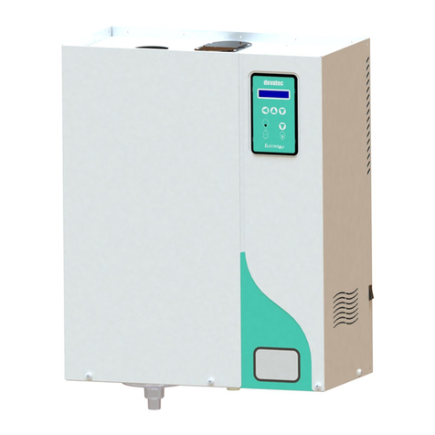
Devatec
Devatec ElectroVap MC Series User manual

Devatec
Devatec ELECTROVAP RTH User manual
Devatec
Devatec ELECTROVAP RTH-LC User manual
Devatec
Devatec ELMC 5 User manual
Devatec
Devatec AC4 User manual

Devatec
Devatec ElectroVap MC Series Release Note
Devatec
Devatec ElectroVap CMC User manual
