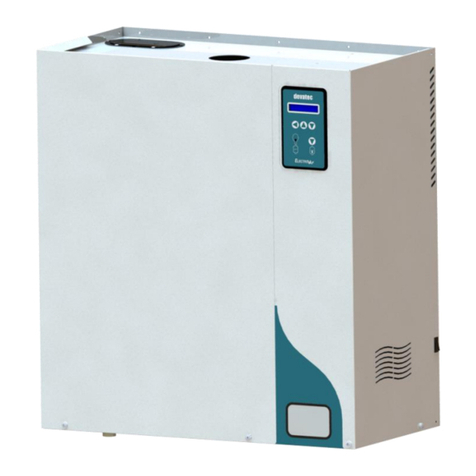
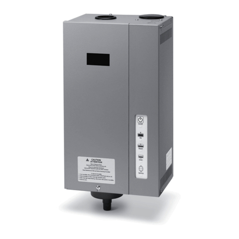
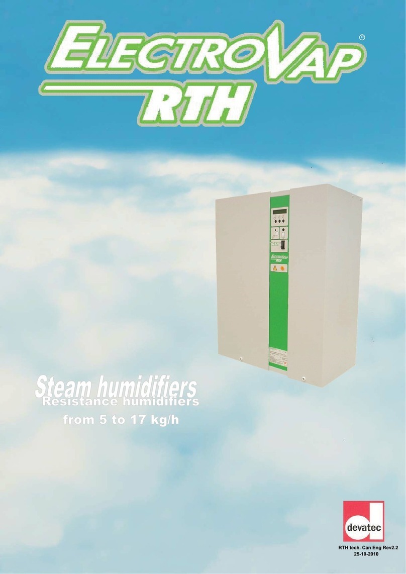
Devatec ELECTROVAP RTH User manual

Pictures for illustrating purposes only
Technical manual
Resistive steam humidifier
R

Pictures for illustrating purposes only 2
Product accreditation 3
Safetyinformation 4-5
Unit wall installation
Dimensions 6
Wall mounting 7 to 9
Water connection 10
Steam outlet 11
Condensate draining 12-13
Steam dispersion pipe 14
Steam pipe positioning 15 to18
Steam pipe installation 19
Room ventilation unit 20
Electrical installation
Electrical table 22 to 27
Electrical wiring 28-29
Control connection 30
Connecting options 31-33
RTH wiring diagrams 34 to 47
Setting up 48
Software assistant
User information menu 49-50
Humidifier status menu 51
Changing parameters menu 52-53
Alerts & warnings 54
Maintenance
Steam tank maintenance - RTH 5 to 50 55-56
Steam tank maintenance - RTH 60 to 100 57 to 59
Valve maintenance 60
Spare parts 61 to 70
ELECTROVAP RTH-V2
Contents

Pictures for illustrating purposes only 3
ELECTROVAP RTH-V2
Product accreditation
DIRECTIVES APPLIED
Electromagnetic Compatibility Directive : 89/336/EEC, 2004/108/EC
Low Voltage Directive : 73/23/EEC, 2006/95/EC
« Machinery » Directive: 98/37/EC, 2006/42/CE
The humidifier complies with :
EN 61000-6-3: Electromagnetic compatibility generic requirements (residential, commercial
and light industries)
- EN 55022 class B; conducted and radiated emission limits
EN 61000-6-2: Electromagnetic compatibility (EMC) - Generic standards—Immunity for in-
dustrial environments;
- EN 61000-4-3: Radiated, radio frequency, electromagnetic field immunity test
- EN 61000-4-6: Immunity to conducted distrubances induced by radio frenquen-
cy fields
- EN 61000-4-4: Electrical fast transient/burnt immunity test
- EN 61000-4-5: Surge immunity test
- EN 61000-4-2: Electrostatic discharge immunity test.
EN 60335-1: Low voltage : safety of electrodomestical devices and similar
EN 60335-2-88: Low voltage : safety of electrodomestical devices and similar, concerning
humidifiers
EN 60204-1: Safety of machinery—Electrical Equipment of machines—Part 1 : General
requirements
Manufacturer’s name & address
devatec
SAS
87 Rue Feu Saint Eloi
76550 Ambrumesnil - FRANCE
Type of equipment
Steam humidifier
Model name & series
ELECTROVAP RTH
Year of manufacturing
2007
We the undersigned, hereby declare that the equipment specified above complies
with the above-mentioned Directive(s) and Standard(s).
Name : FRAMBOT Jean-François
Position : General Manager
Date : 05.06.2008
Signature:

Pictures for illustrating purposes only 4
IMPORTANT
Please read, heed and follow the enclosed safety information and the warning labels
inside the humidifier before installation or maintenance.
Warnings & safety symbols
Warning : This symbol is used to designate a danger of injury or potential damage to the sys-
tem.
Caution : High voltages are present inside the humidifier. All works concerned with the elec-
trical installation must be carried out by skilled and qualified personnel.
Caution : Danger of scalding ! The ElectroVap RTH generates steam during operation and
therefore surfaces and pipe-work become very hot. Ensure that equipment not sustaining high
temperatures be kept away.
Warning : the end user should ensure that the equipment be disposed of according to the
local prevailing regulations.
Delivery and storage
Any loss or damage during delivery should be reported to carrier by registered letter within 3 working
days and be advised to devatec or to authorized dealer.
It is recommended that the ElectroVap RTH humidifier be kept in its transit packaging for as long as
possible prior to maintenance. If the humidifier is to be put into storage prior to installation, it must be
stored under cover and protected from physical damage, dust, frost, rain and humidity. More than 6
months storage is not recommended.
ELECTROVAP RTH-V2
Safety information

Pictures for illustrating purposes only 5
IMPORTANT
This section should be read carefully to ensure safe and correct installation of your humidifier.
GENERAL
This manual contains all details necessary for the planning and installation of the ElectroVap RTH humidifier. In addition
commissioning and maintenance details are included.
The manual is intended for use by engineers and properly trained technical personnel. Maintenance, servicing or repair
work must only be carried out by suitable skilled and qualified personnel, the customer must be responsible for ensuring
their suitability.
Any risks or hazards, especially when working from ladders or towers should be identified by a skilled and
Health and Safety representative and effective control measure put in place.
No liability will attach to the Distributor if any damage, injury or accident is attributable to inattentive, inappropriate, negligent
or incorrect operation of the machinery whether or not caused deliberately. Always isolate all electrical and water supplies
before commencing any maintenance.
Every effort has been made to ensure details contained in this manual are correct, however, in view of the wide range of
conditions experienced in air handling systems, the information provided should only be used as a guide. Please contact
your Agent if any doubt.
Correct use
ElectroVap RTH humidifiers are ONLY intended for use with air handling systems or direct air humidification.
ANY OTHER APPLICATION IS NOT CONSIDERED USE FOR THE INTENDED PURPOSE. THE MANU-
FACTURER CANNOT BE MADE LIABLE FOR ANY DAMAGE RESULTING FROM INCORRECT USE.
Water
ElectroVap RTH humidifiers are designed to be used with mains, demineralized R/O with a minimum conduc-
tivity of 30 μs or softened water. On no account attempt to introduce any other fluid or chemical into the sys-
tem. Water supply should not exceed 6.0 bar and installation should comply with local regulations.
Electricity
All work concerned with electrical installation MUST only be performed by skilled and qualified technical personnel (eg elec-
trician or technicians with appropriate training). The customer MUST be responsible for ensuring their suitability.
It is the duty of the installer to ensure that suitable sized cables and MCB protection is provided. Please observe the local
regulations concerning the provision of electrical installations.
Warranty
A two year warranty term—cost and labor—is applicable to the parts of the ElectroVap RTH to the exception
of the consumable parts (valves, cylinders or parts of cylinders) provided our recommendations of use &
maintenance have been adhered to. Failure to specify and fit original parts and accessories will invalidate our
warranty.
NOTE
The manufacturer’s policy is one of continuous research and development. He therefore reserves the right to
amend without notice the specifications given in this document.
The photographs are for illustrating purposes only.
ELECTROVAP RTH-V2
Safety information

Pictures for illustrating purposes only 6
ELECTROVAP RTH-V2
Dimensions
11
1
1
1
1
1
1
1
1
1
1
1
1
1
1
1
AC
DE
FG
I
H
B
Face Côté
H
F
A
D
N
M
N
O
L
Face
RTH-V2 5 to 50 RTH-V2 60 to 100
mm mm
A Width 805 1200
B Height 750 750
C Depth 345 345
D Steam outlet 1 485 488
E Steam outlet - Side view 176 176
F Tank draining - Front view 730 759
G Tank draining - Side view 175 53
H Entrée d’eau - Face 710 692
I Water inlet - Side view 310 310
L Electrical wire outlet diameter 40 - 2x16 40 - 2x16
M Steam outlet 2 - 538
N Overflow draining - Front view 772 847
O Overflow draining - Side view 304 310
kg kg
Weight in operation 75 140
Gross weight (packed) 45 70
Front Front Side

Pictures for illustrating purposes only 7
x Unpack the unit and check for any dama-
ge. A drilling template is supplied with
the packing : make sure to pick it up
before throwing away the packing ma-
terial.
x Damage to packing and/or unit must be
noticed to carrier by registered letter wi-
thin 3 working days.
x Provide free space all around the unit : 1 m. to
1.20 m. from the floor of the humidifier, 1.25
m. ahead & 0.80 m. on the right hand side for
allowing access for maintenance.
x Flatten the supplied drilling template
against the mounting wall and mark the
mounting holes. Drill the 7 (seven) holes
(for RTH 5 to 50) or the 11 (eleven) holes
(for RTH 60 to 100).
x Insert screws and bolts appropriate for
support (3 upwards and 4 (RTH 5 to 50)
or 8 (RTH 60 to 10) downwards (see af-
ter page 8).
x Screw the 3 (three) upper screws allo-
wing about 10 mm for hanging the cabi-
net. Hang the cabinet and tighten the
upper screws for securing the mounting.
x Untighten the screwing knob (1) a little,
tip the stainless steel tank (2) up to tigh-
ten the tank holding steel cord (3).
x Take the cover off the water level tank
(4).
1
2
3
4
Drain hose (supplied)
ELECTROVAP RTH-V2
Unit wall installation

Pictures for illustrating purposes only 8
60
110
31
60
127,5 260
260187,5 294,5
70
60
60
7 trous O8,5mm
Unlock the tank cap and lay it upside down on the top
of the humidifier.
x Release the holding steel cord while holding the
tank;
x Let the tank gently tip under it stops;
x Insert screws on 4, 5, 6 & 7 and thighten up all the
7 (RTH 5 to 50) or 11 (RTH 60 to 100) screws.
You can now :
x Tip the tank back to intermediate position and at-
tach the tank holding sheet cord ;
x Put the tank cover back and lock it with the 4 fas-
teners ;
x Reconnect the high water level wires;
x Set the humidifier tank back to upright position and
screw up knob 1.
4,5,6,7
RTH 5 to 50
12 3
45
76
55cm
ceiling
(continued)
ELECTROVAP RTH-V2
Unit wall installation
7 x Ø 8.5 mm holes

Pictures for illustrating purposes only 9
100
520 580
52,7
44,5 260 279 260
31
110
11 trous
O
8,5mm
RTH 60 to 100
1 2 3
4 5
76
8 9
1110
x For a ground installation, support legs
are available (s.a. attached pictures) :
- Part nb : 999995 for RTH 5 to 50
- Part nb : 999993 for RTH 60 to 100
ref: 999995 ref: 999993
(continued)
ELECTROVAP RTH-V2
Unit wall installation
11 x Ø 8.5 mm holes

Pictures for illustrating purposes only 10
A fresh mains cold water service should be used to supply the
unit. The water pressure should be between 1 & 6 bars & should
not exceed 40°C in temperature.
The water supply connection is under the bottom of the unit. The
humidifier is delivered with a water inlet hose of 50 cm long with
a 3/4" female fitting to the cold water supply. A direct copper
connection is PROHIBITED.
A check valve should be located on the mains and cold wa-
ter service connection to the unit.
The inlet valve base has a basket filter (s.a. page 36).
The RTH humidifier uses water to produce steam so leaka-
ge may happen causing potential damage. If an installation
in false ceiling or above prime rooms (such as museum,
exhibition or laboratory rooms) is considered, ensure that
the floor below the humidifier is constructed from water-
proof materials (with draining facilities) to withstand any
water spilling during servicing or if a problem occurs.
Information about the water quality : chloride concentration :
< 75mg/l, phosphate concentration : < 5mg/l, chlorine consentra-
tion (3 to 6° dA) : < 100mg/l, poor concentration inCO2, organic
elements in poor concentration.
The RTH humidifier can run with the following water quali-
tiers :
x Tap or raw water : water TH between 5° and 40° French
grade.
x Demineralized water : 30μS minimum (caution : the de-
mineralized water is corrosive; use appropriate piping ma-
terial : inox, PVC)
x Softnened waters (not recommanded)
The cation exchangers (softeners) do not suit for the water supply as they do not bring down the mineral salt
content disolved in the water, the polyphosphate measuring devices as well.
A water softener consists basically in replacing a calcium ion by a sodium ion the solubility capability of which is
about 7 times higher. So a water softener does not affect the quantity of mineral salts contained in the water but
alters their nature.
An excess of sodium chloride may generate foam which disturbs greatly the correct running of the humidifier. It
is essential that a duplex softener be used.
A small volume of tap water must be added to the softener water to get a TH value of 10° minimum
(however a TH value of 12° is highly recommended). A water analysis should be made to determine the
sodium chloride content.
We would not recommend the use of cation exchangers as this increases functionning costs significan-
tly.
Water supply service
Check valve
Water inlet hose with 3/4"
female union
ELECTROVAP RTH-V2
Water connection

Pictures for illustrating purposes only 11
1. Use preferably hose from our supply
NB : when brand new hoses are installed, a smell of burning may be smelt during the first running of the
steam humidifier. This is normal and will eventually dispel.
2. Number of steam outlets :
RTH 5 to 20 = 1 x Ø60 mm (Ø60 / Ø40 mm contriction union to consider, see after page n°14)
RTH 30 to 50 = 1 x Ø60 mm
RTH 60 to 100 = 2 x Ø60 mm
3. The RTH humidifier can be used with pressure ducts (P) having the following characteristics :
xIf P is inferior to 220mm CE (Water column) i.e. 2157 Pa.
xIf P is between 220mm CE and 370mm CE (3627 Pa.) , our optional filling cup plateform must be used.
4. Please adhere to the recommendations given underneath for the installation of the steam hose according to one of
the shown examples, the most suited to your installation. A set of hose clamps is supplied for ensuring a correct
installation.
Install the optional 300 mm long flexible steam hose sleeve(s) onto the steam tank outlet(s). Then with a 150 mm
long stainless steel (optional) union, join the Ø60 mm steam hose to this (these) sleeve(s). Make sure to keep the
steam hose still while connecting it to the sleeve(s). It is also possible to connect a stainless steel or copper
pipe to the sleeve(s).
The humidifier should be located within 3 m. of the steam distribution pipe. If the distance is superior to 3 m.
insulated steel or copper pipe of a slightly larger diameter must be used.
TAKE CARE : The steam hose must be kept as tight as possible. If it happens to be pinched or kinked, this can
cause the heating elements to overheat and to be destroyed due to an incorrect detection of a too low water level
inside the cylinder.
Radius of bend for steam hose :
- Ø 40mm steam hose = 400mm minimal radius
- Ø 60mm steam hose = 750mm minimal radius
ELECTROVAP RTH-V2
Steam output
3mmaxi
500 mm mini
Example a Example b
500 mm mini
3mmaxi
10°mini
Ø60 mm stainless steel
union (option)
Keep the hose tight before
joining it to the sleeve(s).
70-90 ring clamp supplied
with the humidifier
Ring bearing clamp
supplied with optional
stainless steel union.

Pictures for illustrating purposes only 12
Fig.1
Fig.2
Fig.3
Overflow hose
Ø40mm drain hose (supplied)
Overflow
hose
Ø40mm drain hose
(supplied)
Overflow
hose
The following drawings show the water draining connections that
should be made.
1. The devatec supplied steam hose should be used :
RTH 5 to 100 : 1.5 m Ø 40mm hose with 1 hose clamp (supplied).
This hose is designed to be connected to the draining system. Regular
replacement is recommended.
2. If rigid piping is used, it must be heat (100°C) and pressure resistant
PVC material and have a 100 mm wide diameter.
3. The discharge hose must be free from any obstacle. It is recommended
that each humidifier has its own drain pipe and tank arrangement in
case a number of humidifiers is installed.
4. Use water tanks with a lid that has water collecting facilities (option on
request) (s.a. drawings 1, 2 and 3).
5. A funnel can also be used (s.a. pict. 3), but it should be offset from the
underside of the unit to prevent any steam and/or condensation from
getting into the cabinet. The installation of a siphon (as per the draining
hose) is recommended and arrangements for holding water spilling
should also be made.
6. CAUTION : keep a minimum pitch of 10° for both the draining & over-
flow hoses of the humidifier and for general drain pipe (s.a. pictures 1,
2, 3 and 4).
Ø40mm drain hose
(supplied)
ELECTROVAP RTH-V2
Condensate draining

Pictures for illustrating purposes only 13
Drain water cooling kit (option)
How it works
The draining water of a steam humidifier is very hot and it
may be necessary to cool it down. This unsophisticated device
makes it possible to cool it down to 65°C (149°F) when the fee-
ding water is around 15°C (59°F).
Whenever the humidifier drains, the water inlet coil(rep. 7)
of the cooling device is prompted and sends cold water inside
the drain hose (rep 11).
Installation
This cooling device is physically attached to the water
inlet valve via the 3/4" connecting screw (rep. 4) and on the
drain valve via the 1 1/2" connecting screw ( rep. 12) of the drain
valve. The cooling inlet valve is electrically supplied by connec-
tion to the drain valve coil.
This option can be installed on all existing humidifiers..
Cold water inlet
Humidifier drain valve outlet
Option—Drain water cooling kit (ref: 311800540)
rep 7
rep 4
rep11
rep 12
ELECTROVAP RTH-V2
Condensate draining

Pictures for illustrating purposes only 14
The steam from the boiler enters the
duct or an air handling unit via a steam distri-
bution pipe.
In order to obtain the optimum perfor-
mance of the humidifier, select the longest
pipe.
ExpressPack
Steam distribution pipe
Steam distribution
pipe for
RTH 5 to 20
L1
mm
D40 -L290 290
D40-L590 590
D40-L790 790
D40-L1000 1000
D40-L1250 1250
D40-L1500 1500
Steam distribution selection table
Ø60 or
Ø40mm
Ø8 or
Ø13mm
ExpressPack
Steam distribution
pipe for
RTH 30 to 100
L
mm
DL-1 354
DL-1,5 507
DL-2 659
DL-3 964
DL-4 1269
DL-5 1574
DL-6 1889
DL-7 2153
DL-8 2488
DL-9 2793
DL-10 3098
L1
mm
254
407
559
864
1169
1474
1779
2083
2388
2693
2998
Ø60/40mm contriction
union used with pipe
Ø4 0 m m f o r
RTH 5 to 20.
L1
The Armstrong ExpressPack is a
bespoke steam humidification system made
to suit your configuration and ready to install
in a ventilation duct.
It permits to have vapor trails
(absorbing distances) as short as 600 mm.
For further reference, please contact devatec
or their authorized agent.
ELECTROVAP RTH-V2
Steam dispersion pipe
100mm

Pictures for illustrating purposes only 15
ELECTROVAP RTH-V2
Steam pipe positioning
Evaporation distance or vapor trail « D »
A certain length is required so that the steam coming out of the steam distribution pipe be absorbed by the
air. All along this length, descrided as the evaporation distance, the steam can still be seen in the airflow as a mist
which can condensate in water against any obstacle if placed within. To prevent condensation, this evaporation
distance should be calculated before positioning the steam distribution pipe.
How to calculate the evaporation distance « D » (FAST METHOD)
In order to determine the evaporation distance, the attached calculation table can be used :
Nota bene : this calculation table is to be used for temperatures between 10°C and 25°C.
HR1 = relative humidity of air before humidification in %.
HR2 = relative humidity of air after humidification in %.
D mini = minimum humidification distance in meters (m).
Minimal humidification distance
The steam distribution pipes must be positioned after the minimum humidification distance calculated with
the help of the above table.
POSITIONING OF THE STEAM DISTRIBUTI0N PIPE
% RH1 inlet air
5 10 20 30 40 50 60 70
% HR2 outlet air
40 0.9 0.8 0.7 0.5 - - - -
50 1.1 1 0.9 0.8 0.5 - - -
60 1.4 1.3 1.2 1 0.8 0.5 - -
70 1.8 1.7 1.5 1.4 1.2 1 0.7 -
80 2.3 2.2 2.1 1.9 1.7 1.5 1.2 0.8
90 3.5 3.4 3.2 2.9 2.7 2.4 2.1 1.7
Minimum humidification distance « D » in m.
Before / after fan before / after heater/filter
D D 1.5 x D 5cm
2,5 x D before thin particule filter

Pictures for illustrating purposes only 16
A high humidity limit humidistat must be installed in the duct to stop the humidifier in case the
level of humidity exceeds the preset value.
In case the recommended distances cannot be met, please contact devatec or their authorized
agent for an alternative solution.
If accurate values cannot be reached, a distance of 2 m. should be considered as a minimum
distance between pipes & obstruction and 3 / 4 m. before sensor or humidistat.
Before a junction before an air opening before a humidity sensor
D
D
5 x D
0,5 x D
Before / after a constriction before an expansion before a bend
D
0,5 x D
(CONTINUED)
ELECTROVAP RTH-V2
Steam pipe positioning

Pictures for illustrating purposes only 17
11
1
1
660H> mm
H3
H2
H1
H2
410H > mm
19,61
1
H3
H2
1
H1
11
1
H3
H2
H1
480H>mm
550H > mm
11
1
H1
H2
H2
1
H3
270H > mm
1
H3
8,
5
1
H1
Please meet the following dimensions and spaces according to your configuration. For further information, please
contact devatec or their authorized agent.
H1 = 110mm = Minimum height between the duct floor and the axle of the steam pipe.
H2 = 140mm = Minimum distance between two pipes.
H3 = 160mm = Minimum height between the duct top and the axle of the steam pipe.
The H3 distance can be 80 mm at the shortest in case the steam pipe is installed at an angle of 30°.
The arrow shows the direction of the air flow.
ELECTROVAP RTH-V2
Steam pipe positioning

Pictures for illustrating purposes only 18
1
D
1
5
°
In vertical ducts where the air flow is upward
or downward, the steam distribution pipe(s)
must be tilted by 15° sideways.
590
47,2
d/2
d
In duct with limited height, the distribution pipe(s) can be tilted
by 30 ° to get the 80 mm minimum height.
D = Humidification distance
d = Duct diameter
30°
1
H3
Duct installation with ExpressPack - RTH 5 to 50 Duct installation with ExpressPack - RTH 60 to 100
Condensates
Air flow
DRAIN
Condensates
DRAIN
Air flow
(continued)
ELECTROVAP RTH-V2
Steam pipe positioning

Pictures for illustrating purposes only 19
4590
10
10
133
153
153
133
O
6
4x
138
d
70
O
5
For ensuring the best steam distribution possible, we would recommend to install the steam pipes in either
diameter as per the two methods described underneath.
How to install in a duct
How to attach the pipe en (inside the duct)
Your steam pipes must be screwed onto the ventilation duct by the fixing plate with a set of 4 bolts and nuts of Ø
5 mm.
The length of the bolts will be according to the thickness of the ventilation duct.
The end of the steam pipe should be attached to the duct with a threaded rod of Ø 5 mm
going from the dedicated hole of the fixing plate to the outside of the duct and attached by a
couple of nuts (method 1). A rail attached to the inner side of the duct can also be used - a
5mm bolt and nut are used to settle the pipe on the rail (method 2).
The steam pipe must be at level with the duct.
Threaded rod
Rail
Method 1 Method 2
Steam pipe Ø40mm Steam pipe Ø60mm
ELECTROVAP RTH-V2
Steam pipe installation
O
9
Steam pipe Ø40mm
Steam pipe Ø60mm
O5
4X
100
140
124
84
8
8
3690
50
124
d

Pictures for illustrating purposes only 20
3mètresmaxi
Three ventilation packs permit the use of the humidifier in direct in-space applications
where there is no ductworks.
The Blower Packs BP1 & BP2 can be set on the top of the RTH 5 to 30 while a wall set-
ting is required for the models ranging up. The EHF III blower pack also requires to be
wall installed. The distance between the humidifier and the ventilation pack(s) should not
exceed 3m.
For use with RTH 60, two BP2 should be installed while two EHF III must be used in
combination with RTH 70 to 100, equally distant (X). (X1=X2).
A Ø40/60 mm reductor union must be used for connecting the BP1 or BP2 to the humidi-
fier while a Ø 40/50 mm reductor must be used for connecting the EHF III to the humidi-
fier
Allow a 3 m. distance ahead to the ventilation pack for a free diffusion of steam.
The electrical connection of the ventilation packs to the humidifier is via terminal block 3
& 4 on the DIN rail.
For use and installation of the Blower Pack ventilation units, please refer to the Blower
Pack technical manual available in English.
As far as the EHF-3 is concerned, please revert to the recommendations given on
the EHF-3 information sheet. Never connect the EHF-3 unit on the terminals 3 & 4
of the humidifier when a 100VA transformer is installed inside the ElectroVap RTH
humidifier.
Width Heigth Depth Weight
Kg dB Kg/h maxi
output m3/h Connecting Ø
Compatible
with
BP1 260mm 170mm 285mm 2 40 15 160 Ø 25 mm RTH 5 to 15
BP2 260mm 170mm 285mm 2.6 40 30 320 Ø 40 mm RTH 20 & 30
EHF3 495mm 356mm 406mm 15 48 55 780 Ø 50 mm RTH 40 to 50
ELECTROVAP RTH-V2
Room ventilation packs
0,50m mini
1m mini
Dimensions & characteritics
BP1 & BP2
Examples of installation
EHF-3
TAKE CARE :
Attach hose on wall before connecting
it to Blower Pack.
15°
15°
1 1
X1 X2
Equilibrage du réseau
vapeur X, soit X1=X2
Steam distribution Y union
Ø60mm - 2xØ40mm
(code: DIV0019)
Steam hoses should be
equally distant — X1=X2
Other manuals for ELECTROVAP RTH
1
Table of contents
Other Devatec Humidifier manuals
Devatec
Devatec ElectroVap RTH Series User manual
Devatec
Devatec ElectroVap Installation instructions manual
Devatec
Devatec AC4 User manual

Devatec
Devatec ElectroVap MC Series Release Note
Devatec
Devatec ElectroVap CMC User manual
Devatec
Devatec ElectroVap MC Series User manual
Devatec
Devatec ELECTROVAP RTH-LC Series User manual
Devatec
Devatec ELECTROVAP RTH-LC User manual
Devatec
Devatec ELMC 5 User manual

Devatec
Devatec ElectroVap User manual
