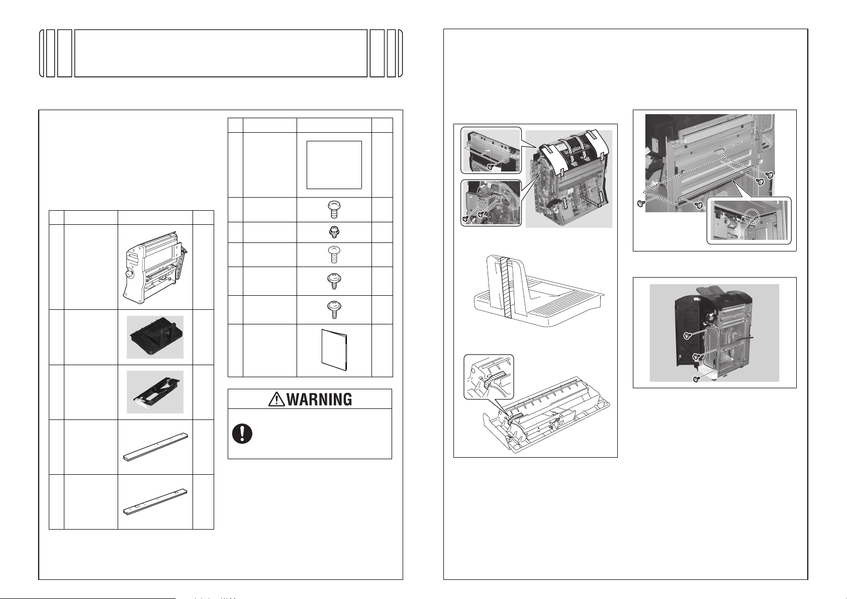
E-6
<Half-fold position adjustment>
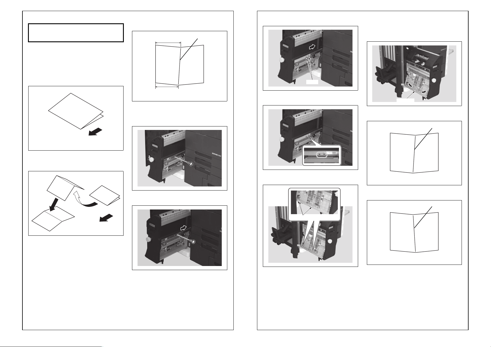
1. Unfold the paper that exits the machine and lay
the paper with the ridge facing up.
2. Fold the paper shown in step 1 in half and unfold
it again.
3. Check the crease for deviation
(Measure width A).
Reference: 0 ± 1.0 mm
4. Display the Service Mode screen.
(For details of how to display the Service Mode
screen, see the Service Manual.)
5. Touch “Finisher.”
6. Touch “FS-FN adjustment.”
7. Touch “Half-Fold Position.”
8. Check that “ALL” is displayed in reversed.
[If the crease deviates as shown below]
Using the key, set the numeric value and
touch “OK.”
[If the crease deviates as shown below]
Using the key, set the numeric value and
touch “OK.”
9. Touch “OK.”
10. Touch “Exit” on the Service Mode screen.
11. Make copies again and check the crease posi-
tions deviate.
Exit direction
A10DIXC049DA
A10DIXC050DA
A10DIXC052DA
A
Crease produced in step 2
Crease
A10DIXC052DA
A
A10DIXC053DA
A
<Center staple position adjustment>
1. Unfold the paper that exits the machine and lay
the paper with the ridge facing up.
2. Check the staple position for deviation from the
crease (Measure width A).
Reference: 0 ± 1.0 mm
3. Display the Service Mode screen.
(For details of how to display the Service Mode
screen, see the Service Manual.)
4. Touch “Finisher.”
5. Touch “FS-FN adjustment.”
6. Touch “Center Staple Position.”
7. Check that “ALL” is displayed in reversed.
[If the Staple positions deviate as shown below]
Using the key, set the numeric value and
touch “OK.”
[If the Staple positions deviate as shown below]
Using the key, set the numeric value and
touch “OK.”
8. Touch “OK.”
9. Touch “Exit” on the Service Mode screen.
10. Make copies again and check the staple posi-
tions deviate.
Exit direction
A10DIXC051DA
A10DIXC054DA
AStaple position
A10DIXC054DA
A
A10DIXC055DA
A