manuals.online logo
Brands
  1. Home
  2. •
  3. Brands
  4. •
  5. Develop
  6. •
  7. Printer Accessories
  8. •
  9. Develop PF-507 User manual

Develop PF-507 User manual

E-1
INSTALLATION MANUAL
A3PF-9950-00
PF-507 Paper Feeder Unit
1BS0832701
I. Accessory parts
Note:
This manual provides the illustrations of the acces-
sory parts and machine that may be slightly differ-
ent in shape from yours. In that case, instead of
the illustrations, use the appearance of your
machine to follow the installation procedure. This
does not cause any significant change or problem
with the procedure.
II. Installation procedures
Note:
When the paper feeder unit(s) is installed in the
machine, perform steps 1 to 4 below and then per-
form steps 5 to 9 in <Installation of one paper
feeder unit to another> described on page E-3.
1. Turn off the machine and unplug the power cord
from the power outlet.
2. Remove the protective tape and cushioning
materials.
3. Remove the rear cover of the paper feeder unit.
(One screw)
No. Name Shape Q’ty
1. Tray label/
Paper size
label
1
set
2. Screw A
(4 × 12 mm) 4
3. Screw B
(3 × 8 mm) 1
4. Installation
manual
1
set
After unpacking, be sure to get rid of the
packaging materials and keep them out of
the reach of children.
Putting the head in the plastic bag
involves danger of suffocation.
9738
9646
4980IXC019DA
A3PFIXC009DA
A3PFIXC010DA
Rear cover
Applied Machines: 235/215/195
MFP: 23 ppm/21 ppm/19 ppm
Product Code: A3PE/A3R2
E-2
<Installation to the machine>
Note:
When adding multiple paper feeder units to the
machine, see <Installation of one paper feeder unit
to another> on page E-3 and join the paper feeder
units together in advance.
4. Mount the machine while making sure that the
projections on the paper feeder unit are aligned
correctly with the machine.
Note:
• When transporting or moving the machine,
assign adequate number of persons.
• Hold the machine by the locations (four places)
marked in the illustration and raise it while
keeping it in a horizontal position.
• Make sure no harnesses or ground wires are
pinched.
5. Slide out the drawers of the machine and the
paper feeder unit and secure the paper feeder
unit by tightening the two screws at the front.
(Two supplied screws A)
6. Secure the paper feeder unit by tightening the
two screws in the rear. (Two supplied screws A)
A3PFIXC001DA
A3PEIXC025DA
Mark
Mark
Projection
Projection
A3PFIXC003DA
A3PFIXC004DA
A3PFIXC005DA
E-3
7. Connect the ground wire of the paper feeder unit
to the machine. (One supplied screw B)
8. Plug the connector of the paper feeder unit into
the machine.
9. Attach the rear cover removed in the step 3.
(One screw)
* For the following steps, go to “III. Loading the
paper feeder unit with paper” on page E-4.
<Installation of one paper feeder unit to another>
4. Mount one paper feeder unit to another as shown
in the illustration.
Note:
Make sure no harnesses or ground wires are
pinched.
5. Slide out the drawers of each paper feeder unit
and secure the two paper feeder units together at
the front. (Two supplied screws A)
A3PFIXC006DA
Connector
Ground wire
A3PFIXC012DA
A3PFIXC013DA
A3PFIXC014DA
E-4
6. Secure the paper feeder units together in the
rear. (Two supplied screws A)
7. Connect the ground wire of the lower paper
feeder unit to the upper paper feeder unit.
(One supplied screw B)
8. Plug the connector of lower one paper feeder unit
into that of another.
9. Attach the rear cover removed in the step 3.
(One screw)
10. Seeing the steps described in <Installation to the
machine> on page E-2, attach the paper feeder
units to the machine.
III. Loading the paper feeder unit with
paper
1. Slide out the drawer of the lower paper feeder
unit and press down the paper lifting plate until it
locks in position.
2. Load the paper.
Note:
Do not load so much paper that the top of the
stack is higher than the ▼mark and the separator
fingers.
3. Slide the guide plate and trailing edge stop so
that they are pressed tightly up against the edges
of the paper stack.
A3PFIXC015DA
A3PFIXC016DA
Connector Ground wire
A3PFIXC007DA
A3PFIXC017DA
A3PFIXC018DA
E-5
IV. Paper feed check
1. Plug the power cord into the power outlet and
turn on the machine.
2. Press the Paper key to select the tray2.
3. Press the Start key to check for correct paper
feed.
If the paper is not properly fed, perform the fol-
lowing adjustment.
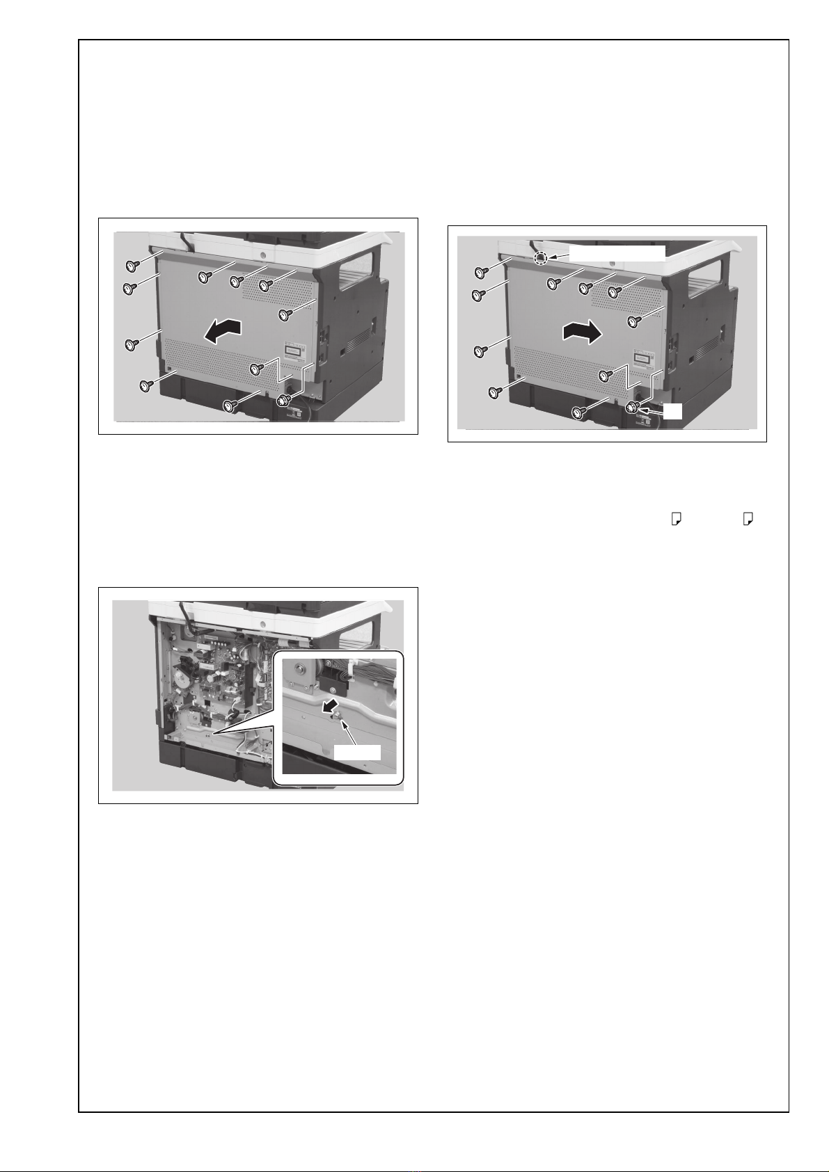
(1) Remove the rear cover. (11 screws)
(2) Loosen the screw shown in the illustration and
adjust the position of the screw. Retighten the
screw.
Note:
Be sure not to push the bracket hard to the direc-
tion of the arrow. If this step is not carried out in
the proper manner as described above, paper
conveyance failure may result.
(3) Make a paper feed check again and confirm
that paper is fed without problem.
(4) Reinstall the rear cover. (11 screws)
Note:
• When the optional reverse automatic document
feeder (DF-625) is installed, make sure that the
harness cover is not detached, and then attach
the rear cover.
• Be aware that only the screw A is different from
other screws.
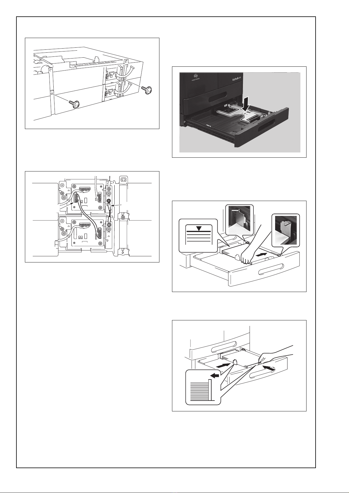
V. CD registration adjustment
1. Load the adjustment tray with A4 or Letter
paper.
2. Display the Service Mode screen. (For details of
how to display the service mode screen, see the
service manual.)
3. Press ▼or ▲key to select “FUNCTION” on the
display.
4. Press the [OK] key.
5. Press ▼or ▲key to select “PRN TEST PAT-
TERN” on the display.
6. Press the [OK] key.
7. Press ▼or ▲key to select the adjustment tray on
the display.
8. Press the [OK] key.
9. Press ▼or ▲key to select “PATTERN1” on the
display.
10. Press the OK key to start the test print.
A3PFIXC019DA
A3PFIXC020DA
Screw
A3PFIXC021DA
Harness cover
A
E-6
11. Measure dimension A of the test print.
Specifications
A4 : 20 ± 2.0 mm
Letter : 11.2 ± 2.0 mm
12. If dimension A falls outside the specified range,
perform the following adjustment procedure.
13. Slide out the drawer and loosen the two indi-
cated screws.
If dimension A is more than the specified range,
move the guide plate in the direction of the arrow.
If dimension A is less than the specified range, move
the guide plate in the direction of the arrow.
14. After the adjustment has been made, produce
another test print and measure dimension A
again.
15. After the adjustment has been made, tighten the
screws which has been loosened in step 13.
VI. Affixing the tray label/paper size label
Affix the tray label or paper size label at the location
shown in the illustration.
Note:
If both are to be affixed, the tray label should be on
the upper side and the paper size label on the
lower side.
A3PFIXC025DA
A
Exit direction
A3PFIXC008DA
Screw
A3PFIXC022DA
A3PFIXC023DA
A3PFIXC024DA

Other Develop Printer Accessories manuals

Develop PF-602 User manual

Develop

Develop PF-602 User manual

Develop Ineo DK-501 User manual

Develop

Develop Ineo DK-501 User manual

Develop PC-208 User manual

Develop

Develop PC-208 User manual

Develop SD-509 User manual

Develop

Develop SD-509 User manual

Popular Printer Accessories manuals by other brands

Lexmark T656 Series user guide

Lexmark

Lexmark T656 Series user guide

GBC Ricoh StreamPunch Pro installation manual

GBC

GBC Ricoh StreamPunch Pro installation manual

Ricoh BN3110 Field service manual

Ricoh

Ricoh BN3110 Field service manual

Konica Minolta LU-302 installation manual

Konica Minolta

Konica Minolta LU-302 installation manual

HP LaserJet LJ 5M instructions

HP

HP LaserJet LJ 5M instructions

INKSUPPLY.COM Canon iP4000 CFS installation instructions

INKSUPPLY.COM

INKSUPPLY.COM Canon iP4000 CFS installation instructions

Ricoh Aficio 1018 operating instructions

Ricoh

Ricoh Aficio 1018 operating instructions

Ricoh Aficio 3228C installation instructions

Ricoh

Ricoh Aficio 3228C installation instructions

Nikon AF-10 user manual

Nikon

Nikon AF-10 user manual

Epson T096220 Material safety data sheet

Epson

Epson T096220 Material safety data sheet

Epson T059720 Material safety data sheet

Epson

Epson T059720 Material safety data sheet

Pitney Bowes W863 Operator's guide

Pitney Bowes

Pitney Bowes W863 Operator's guide

Epson C12C824142 Handling instructions

Epson

Epson C12C824142 Handling instructions

Canon Finisher-R1 General Timing Chart/General Circuit Diagram

Canon

Canon Finisher-R1 General Timing Chart/General Circuit Diagram

Epson T027201 Product information sheet

Epson

Epson T027201 Product information sheet

Sawgrass Technologies R1800 - Stylus Photo Color Inkjet Printer Getting started guide

Sawgrass Technologies

Sawgrass Technologies R1800 - Stylus Photo Color Inkjet Printer Getting started guide

Xerox 980 Hints and tips

Xerox

Xerox 980 Hints and tips

ES&S Ballot on Demand Printing Procedures Manual

ES&S

ES&S Ballot on Demand Printing Procedures Manual

manuals.online logo
manuals.online logoBrands
  • About & Mission
  • Contact us
  • Privacy Policy
  • Terms and Conditions

Copyright 2025 Manuals.Online. All Rights Reserved.