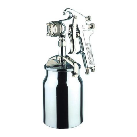
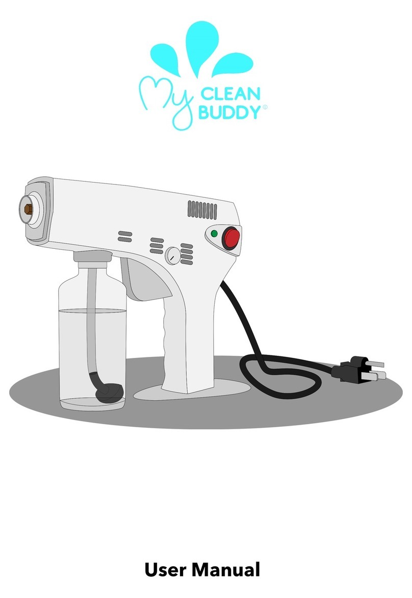
DeVilbiss Cobra 1 User manual
Other DeVilbiss Paint Sprayer manuals

DeVilbiss
DeVilbiss SGA-570 User manual

DeVilbiss
DeVilbiss EXL-520S User manual
DeVilbiss
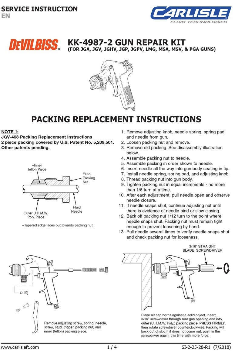
DeVilbiss KK-4987-2 Original operating manual
DeVilbiss
DeVilbiss SB-2-001-J User manual

DeVilbiss
DeVilbiss MBC-ZINC-W User manual

DeVilbiss
DeVilbiss AGF-508 User manual
DeVilbiss
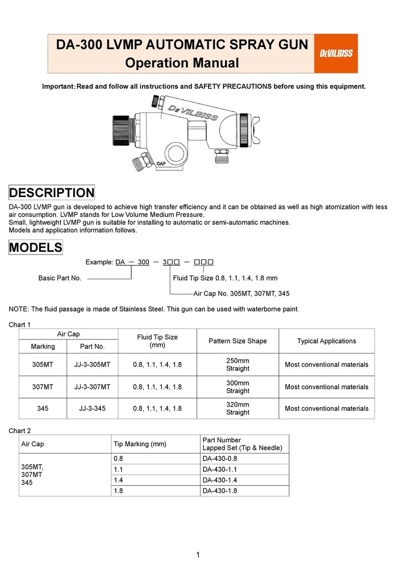
DeVilbiss DA-300 User manual

DeVilbiss
DeVilbiss Compact COM-PS430-18-01 User manual

DeVilbiss
DeVilbiss DEMI 2 Installation manual

DeVilbiss
DeVilbiss Viper User manual

DeVilbiss
DeVilbiss HD-503 User manual

DeVilbiss
DeVilbiss AGXV-540 User manual
DeVilbiss
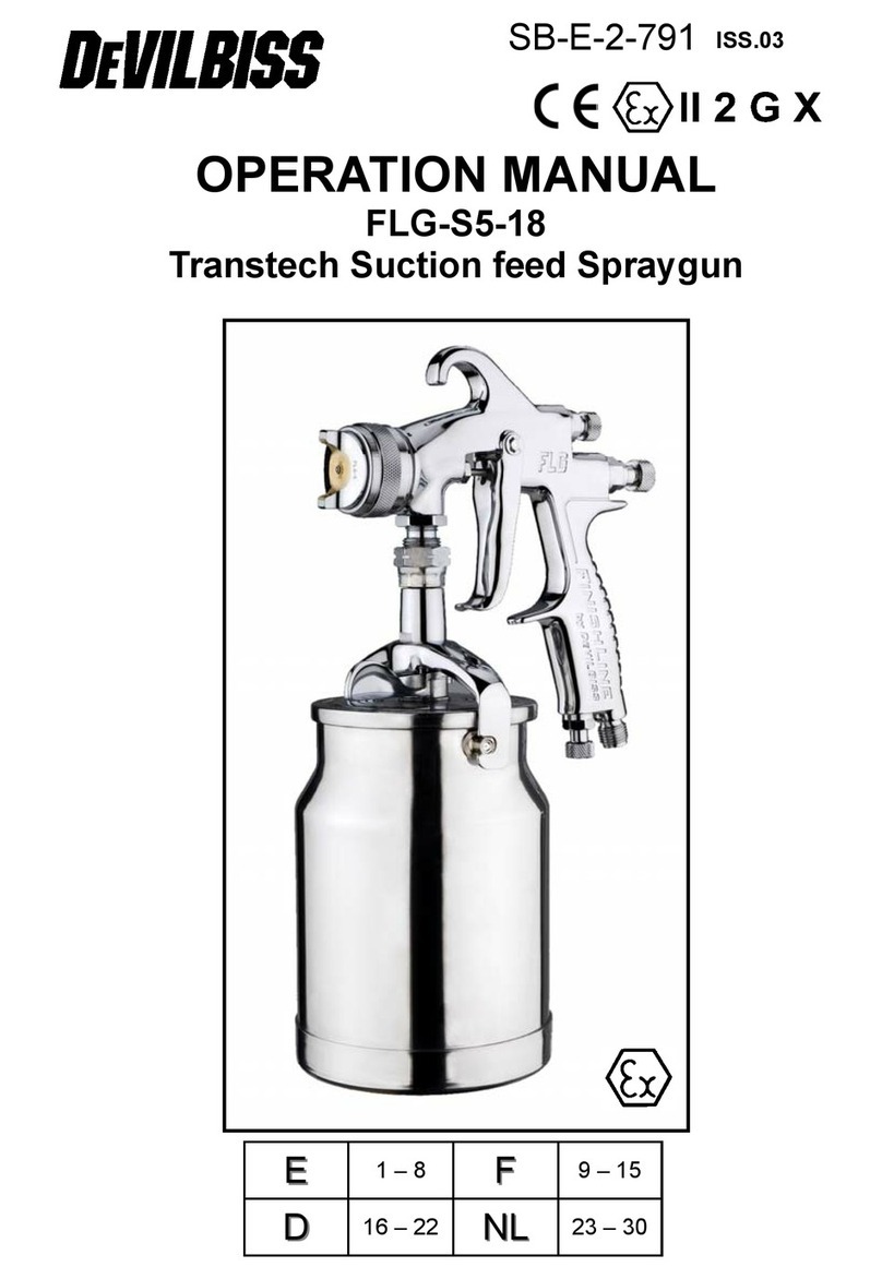
DeVilbiss FLG-S5-18 User manual
DeVilbiss
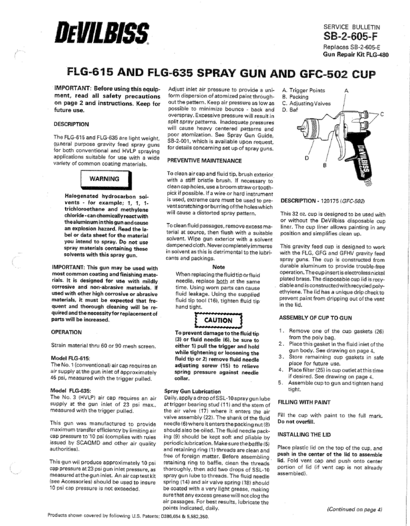
DeVilbiss FLG-615 User manual

DeVilbiss
DeVilbiss JGA PRO Series Service manual

DeVilbiss
DeVilbiss PRI-G310M-14 User manual

DeVilbiss
DeVilbiss MBC-ZINC Reference manual
DeVilbiss
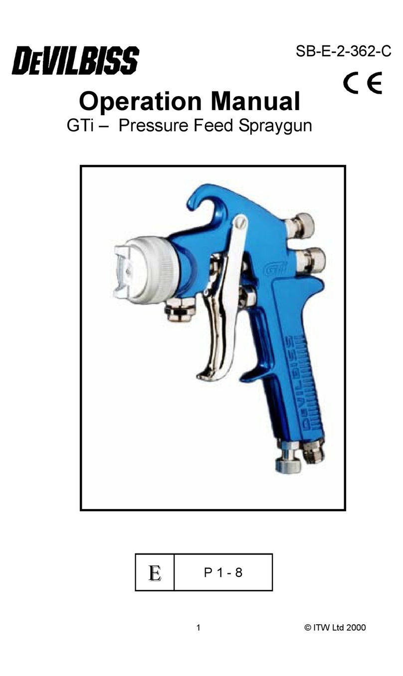
DeVilbiss GTI User manual
DeVilbiss
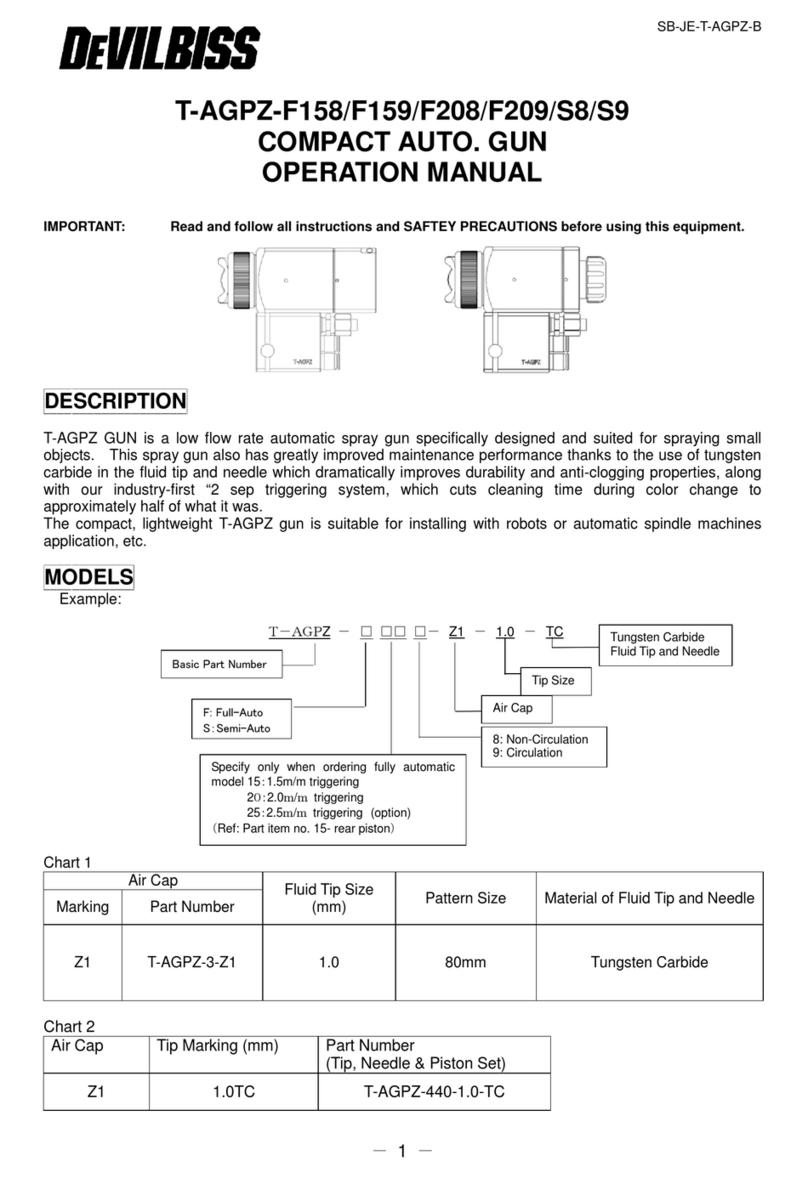
DeVilbiss T-AGPZ-F158 User manual

DeVilbiss
DeVilbiss JGHV User manual
Popular Paint Sprayer manuals by other brands

zogics
zogics Z-DAS instruction manual

KISANKRAFT
KISANKRAFT KK-KBS-165 Operation manual

Matrix
Matrix SG 650 Translation of the original instructions

Anest Iwata
Anest Iwata SGA-3 Installation, use & maintenance instruction manual

paasche
paasche VV Instructions and parts list

Carlisle
Carlisle DeVilbiss JGA-510 Service manual
