DESCRIPTION
The TGC-500-2 cup
is
used
in
applications where
agitation ofmaterial in the sprayguncup is required
to
prevent the settling
of
pigments and solids inthe paint
during application.
An
air
turbine mixing blade lifts
pigments and solids
from
the bottom of the cup and
keeps it in suspension.
An airregulating valveontheturbineairline regulates
the speed
of
the turbine to control the mixing action.
An air adjusting valve is also supplied at the
gun
air
inlet
to
control spray
gun
nozzle atomization.
INSTALLATION
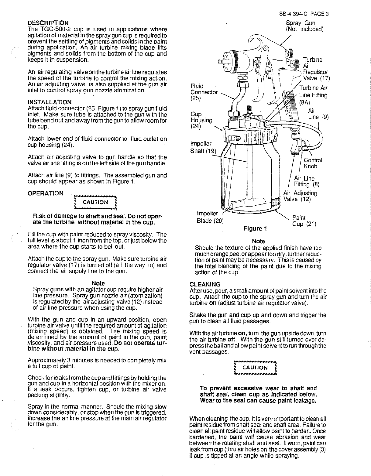
Attach fluid connector(25, Figure
1)
to spray gunfluid
inlet
Make sure tube is attached to the gun with the
tube bend
out
and awayfromthegun to allow room
for
the cup.
Attach lower end of fluid connector
to
fluid outlet
on
cup housing (24).
Attach air adjusting valve to gun handle so that
the
valve airline fitting is onthe leftside of the gun handle.
Attach air line (9) to fittings. The assembled gun and
cup should appear as shown in Figure
1.
OPERATION
Risk
of
damage
to
shaft
and
seal.
Do
not
oper-
ate
the
turbine
without
material
in
the
cup.
Fill the cup with paint reduced to spray viscosity.
The
full level is about i inch from the top, or just below
the
area where the
cup
starts to bell
out
Attach the
cup
tothe spray gun. Make sure turbine air
regulator valve (17) is turned off (all the way in) and
connect the air supply line to the gun.
Note
Spray
guns
with an agitator cup require higherair
line pressure. Spray gun nozzle air (atomization)
is regulated by the airadjusting valve (
i
2)
instead
of air line pressure when using the cup.
With the
gun
and cup
in
an upward position,
open
turbine airvalve until the required amount of agitation
(mixing speed) is obtained. The mixing speed is
determined
by
the amount of paint in the cup, paint
viscosity,
and
airpressure used.
Do
not
operate
tur-
bine
without
material
in
the
cup.
Approximately3 minutes is needed to completely mix
a full
cup
of paint.
Check
for
leaks
from
thecupandfittings by holdingthe
gun and
cup
in
a horizontal position
w1th
the mixeron.
If a leak occurs, tighten cup,
or
turbine air valve
packing slightly.
Spray in the normal manner. Should the mixing slow
down considerably,
or
stopwhen the
gun
is
triggered,
increase
the
air line pressure at the main airregulator
for the gun.
Fluid
Connector
(25)
Cup
Housing
(24)
Impeller
Shalt
(1
Impeller
~ft:;;;~:::;;;~
Blade (20)
Figure
1
Note
SB-4-394-C PAGE 3
Spray Gun
(Not Included)
Air Adjusting
Valve (i
2)
Paint
Cup (21)
Should the texture of the applied finish have too
muchorangepeel
or
appear
toodry,furtherreduc-
tion of paint maybe necessary. This is caused by
the total blending of the paint due to the mixing
action of the cup.
CLEANING
Afteruse, pour, asmallamountofpaintsolventintothe
cup. Attach the cup to the spray gun and turn the air
turbine
on
(adjust turbine air regulator valve).
Shake the gun and cup
up
and down and trigger the
gun to clean all fluid passages.
Withthe airturbine
on,
turn the gunupsidedown, turn
the air turbine
off.
With the
gun
still turned over de-
presstheball andallowpaintsolventtorunthroughthe
vent passages.
To
prevent
excessive
wear
to
shaft
and
shaft
sea!,
clean
cup
as
indicated
below.
Wear
to
the
seal
can
cause
paint
leakage.
Whencleaning the cup, it isvery importantto clean all
paintresiduefrom shaftseal and shaft area. Failure to
clean all paint residue will allow paintto harden. Once
hardened, the paint will cause abrasion and wear
betweenthe rotating shaft and seal.
If
worn, paint can
leakfrom cup (thru airholeson thecoverassembly
(3)
if
cup is tipped
at
an angle while spraying.