Devine WMD-24 PRO Duo User manual

WMD-24 Pro Duo
2.4 GHz Wireless Microphone System
User Manual
The information included in this user manual is subject to change at any time and without notification:
Version:
1.0
Date and author initials: 04-08-2020 RV Revision date and author initials: -

Introduction
Thank you for purchasing the Devine WMD-24 PRO Duo system. Before unpacking the ox and included
components, we recommend reading this user manual thoroughly to ensure that you are completely familiar
with all of the functions this product has to offer. When unpacking the ox, please make sure that all of the
components and accessories listed elow have een included. In the event that the product does not
function as it should, switch off the power and remove the power ca le from the mains power socket efore
contacting your local retailer for advice.
ox contents:
– Devine WMD-24 PRO Duo receiver
– 2x Devine WMD-24 PRO Duo handheld microphone
– 4x 1.5V AA atteries for testing
– 6.35 mm TS jack to 6.35 mm TS jack connection ca le
– power supply
Inspection of the device and included accessories
In the event that the device or any of the included accessories have een damaged or rendered defective in
transit, please contact your local retailer for advice.
Please note: The products seen in the images included in this manual may differ slightly from the product
received.
Contact:
Devine Pro Audio Products
Verrijn Stuartweg 18
4462 GE Goes
The Netherlands
Please do not send any physical products to this correspondence address.
Should you wish to send a product for repairs or for a refund, please contact your retailer for an RM request
(Return Merchandise uthorisation)
The information included in this user manual is subject to change at any time and without notification:
Version:
1.0
Date and author initials: 04-08-2020 RV Revision date and author initials: -

Safety Instructions
Every person involved with the installation, operation and maintenance of this device must:
- Be qualified.
- Be skilled.
- Have read the instructions included in this user manual.
- Be sure that neither the device nor the included accessories are damaged. Should the device or the
included accessories e damaged, please contact your retailer for further advice.
- Ensure that the device is in good working condition and is safe to operate. Please follow the advice and
instructions as they are descri ed in this user manual.
Damage caused y misuse and/or modifications made to the device are not covered y the warranty.
This device does not contain any parts that can e repaired or replaced y the user. Should maintenance or
repairs e necessary, they must e carried out y a qualified technician.
Important information regarding health and safety:
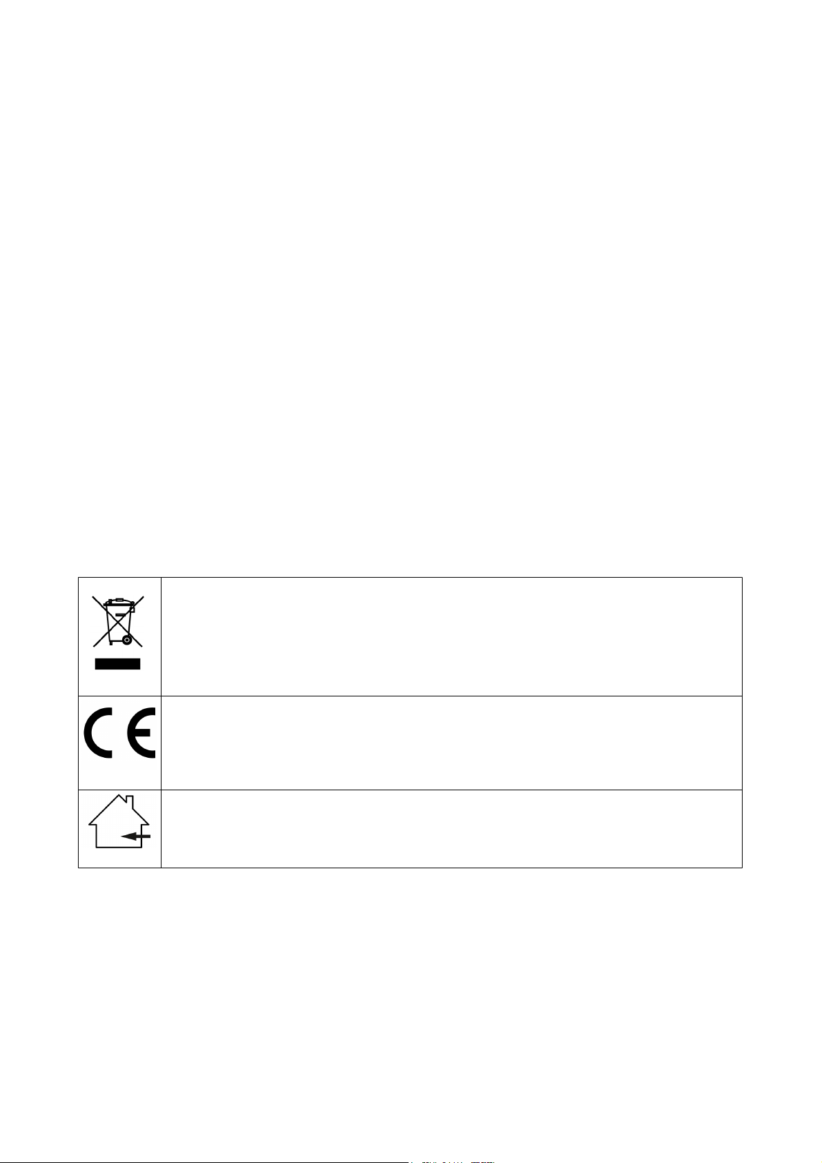
- Do not remove any la els or stickers from this device.
- Do not leave any ca les lying around where they are in danger of causing a tripping hazard.
- The housing of this device must not e opened and any hardware or software that may e present must not
e modified.
- For optimal performance, any inputs of the device should not e fed with a signal higher than necessary.
- The device must only e used indoors; contact with water, rain and moisture must always e avoided. Do
not place any o jects containing liquid on top of the device.
- Remove the device from any near y flames or heat sources; do not place it near flamma le fluids, gasses
or o jects.
- Disconnect this device from a power source if it is not eing used for a long period of time, if maintenance is
necessary, or if it needs to e cleaned.
– Do not pull or tug on the ca le to remove a plug as this may cause damage.
- Do not use any ca les other than those specified in this manual. Do not use defective ca les. Please
contact your retailer if the included or necessary ca les do not function properly with this device.
- In the event that the device is exposed to extreme temperature changes (e.g. transported from a cold
outdoor environment into a warm indoor environment), it should not e turned on until it has reached room
temperature. This is necessary to prevent moisture (condensation) from forming inside the device, which
may cause electric shocks.
Use & Operation Guidelines:
- This device is intended for indoor use and must only e operated y adults.
- This device is not suita le for use y children and must always e operated y an adult.
- This device can only e used in appropriate environments where no damage to the device can occur. Do
not use the device in moist or dusty environments such as:
- indoor swimming pools where chlorine is used
- eaches or any location where sand and/or salt is present
- outdoors
- in indoor spaces where intense heat sources are present, or where it can reach temperature levels
that would e considered uncomforta le for a person.
- Avoid impact and collisions during use and transport. Do not move or transport the device while it is in use.
Avoid using excessive force when installing and operating the device.
- Any user must ecome familiar with the functions of this device efore using it.
- Make sure that the AC/DC adapter and receiver have enough free space to dissipate the heat. Leave a
space of approx. 10 cm around the AC / DC adapter to allow sufficient air circulation.
- In case of emergency, any user must always e a le to disconnect the device from the power source.
Always ensure access to the power supply at one of the following points:
The information included in this user manual is subject to change at any time and without notification:
Version:
1.0
Date and author initials: 04-08-2020 RV Revision date and author initials: -
WARNING!
Keep this device away from moisture, water and rain
to prevent any danger of electric shocks!

- the power input of the device
- the plug that’s connected to the power socket
- an external power lock with on/off switch or dual-pole switch a le to cut the power.
- Should the device not e used in the manner descri ed in this user manual, damages or even injuries could
occur. Devine cannot e held responsi le for any injuries or damages that occur as a result of improper use
of this product.
Storage & Transport:
- This product has een designed for mo ile use and can e transported in its original packaging as long as
it is well protected against shocks and impact. It is also possi le to transport the device in an appropriate
case or flight case with a lined, protective interior that provides a secure fit for all components so that they
are una le to shift in transit.
– This device has not een designed for continuous (24/7) use. The expected lifespan of the device is
increased when the device is turned off regularly.
– When the device is not in use for long periods of time, always disconnect the device from the mains power
and store it in a dust free environment.
– Do not expose the device to extreme temperature shifts.
Housing:
- Frequently inspect the housing of the device and always just efore use. Avoid operating the device if any
large dents or cracks are found in the housing, or if screws are missing. Do not use the device if the housing
is not in good condition. Contact your local retailer or a qualified technician if you are unsure a out the state
of the device.
- Check the device and screws for any corrosion. If any corrosion is found, do not use the device. Contact
your dealer or a qualified technician if the screws or housing show any signs of corrosion.
- Ensure that every power and signal socket is securely fitted. Do not use the device if any of the sockets are
not secure.
- Avoid the uild up of any dust and dirt. Clean the device once a month y disconnecting it from the power
supply and wiping it down with a dry or slightly moist cloth. If the device is used frequently, the device should
also e cleaned more frequently.
Symbol Explanation:
Ensure that this device is disposed of properly. This product falls under the WEEE (Waste
Electrical and Electronic Equipment) directive. The requirements of this directive apply to all
manufacturers and producers of electronic devices in the EU. Do not throw this product away
with normal refuse. Please contact your local authority for more information a out how to
recycle and dispose of these products in your region. By recycling this product in the proper
manner, we can work together to ensure that we can continue to enjoy these kinds of
products and still protect the environment as much as possi le.
CE: The CE logo indicates that this product meets the European norms and requirements to
which it must legally conform.
Suitable for indoor use only: This product was designed for indoor use only. The maximum
environmental temperature must not exceed 40 degrees Celsius (104 degrees Fahrenheit).
The information included in this user manual is subject to change at any time and without notification:
Version:
1.0
Date and author initials: 04-08-2020 RV Revision date and author initials: -

attery safety:
WARNING!
- If the attery is replaced incorrectly, this may cause the attery to explode.
- Only replace a attery with the same attery type.
- Never expose atteries to intense heat, including sunlight, open flames, etc.
- Never store atteries in a hot, high temperature environment. This may cause the attery to explode as well
as the leakage of flamma le liquids or gasses.
- Never expose atteries to an open flame or place them in or near a hot oven.
- Never purposefully damage atteries or try to cut into them as this may cause the attery to explode.
- Do not expose atteries to extremely low air pressures (at high altitudes) since this may cause the attery
to explode as well as the leakage of flamma le liquids or gasses.
- If the device is not in use for a long period of time (a few months, for example), ensure that any atteries
are removed from the device efore it is stored.
- Always immediately remove empty atteries from the device.
- Avoid carrying atteries in a pocket, wallet, or ag. Contact with metal o jects like coins, keys and similar
can cause damage, leakages, or short-circuits.
- Always ensure that atteries are kept out of reach of children.
Recycling:
Never dispose of atteries via household waste. Batteries can contain su stances that are damaging
to the environment. If a attery is recycled using the correct methods, it can e a valua le source of
reusa le materials. Contact your local council for more information a out how est to dispose of
atteries.
The information included in this user manual is subject to change at any time and without notification:
Version:
1.0
Date and author initials: 04-08-2020 RV Revision date and author initials: -

Overview & Use
Receiver:
1. ON/OFF switch
2. Microphone A volume control
3. Microphone A channel set
4. Microphone A channel down
5. Microphone A channel up
6. Central LCD display
7. Microphone B channel up
8. Microphone B channel down
9. Microphone B channel set
10. Microphone B volume control
11. Antenna Microphone A
12. Antenna Microphone B
13. Microphone B alanced XLR output
14. Microphone A alanced XLR output
15. Mix output via 6.35 mm TS jack
16. Power supply input
The information included in this user manual is subject to change at any time and without notification:
Version:
1.0
Date and author initials: 04-08-2020 RV Revision date and author initials: -

Handheld Microphones:
1. Microphone grille
2. LCD-display with status information
3. ON/OFF switch
4. Battery compartment cover (sliding system)
5. Battery compartment for 2x AA atteries
6. Synchronisation point
The information included in this user manual is subject to change at any time and without notification:
Version:
1.0
Date and author initials: 04-08-2020 RV Revision date and author initials: -

Using this System
This wireless microphone system offers a huge num er of options and features. It is therefore strongly
recommended that the tips and advice included elow is read in detail so that you can get the est out of this
microphone system while using it safely.
Legal Use of the 2.4 GHz and
This microphone system operates using the 2.4 GHz wireless and. This is the same and used y WiFi
networks, Bluetooth, and other compara le signals.
This frequency and can e used freely worldwide, and as such, this microphone system can also e used
freely worldwide.
Ensure Optimal Transmitter and Receiver Signal Strength
The iggest disadvantage of using the 2.4 GHz frequency and is that many locations may already e usy
with wireless signal traffic like WiFi networks, Bluetooth signals, and similar signals that operate within or
near the same frequency range. It may also e the case that audience mem ers may have smartphones or
similar gadgets that are constantly scanning for an availa le signal.
In the worst case, this can cause serious pro lems with the performance of the WMD-24 PRO Duo
microphone system.
To prevent or overcome these possi le pro lems, the following measures can e taken:
– Make sure that any other transmitting or receiving device or equipment that operates using the frequency
and is moved at least 1 metre away from the system.
– As much as possi le, try to maintain a clear ‘line of sight’ etween the transmitter and receiver and that
nothing is locking the signal transmission. O structions can include walls, furniture, or audience mem ers.
The less the signal is locked, the more sta le the signal ecomes.
– A good tip is to place the receiver in a relatively high position. This will increase the ‘line of sight’ of the
receiver so that it can etter detect the signal from the transmitter (handheld microphone).
Switching the Receiver On
Before switching the receiver on, ensure that it is placed in an optimum position (as descri ed a ove) on a
sta le surface. Then, connect the DC power supply to the power input of the receiver and plug the power
supply into a compati le mains power socket. Use the Power utton of the receiver to switch it on and off.
Channel Selection
Since the 2.4 GHz frequency and can e usy, the WMD-24 Basic Duo comes fitted with a practical
function that makes it possi le to set a separate channel for oth microphones to avoid any possi le
interference.
One of16 different channels can e selected using the navigation uttons on the front panel of the receiver.
The display will show the selected channel num er as well as the exact 2.4 GHz transmission frequency.
IR Synchronisation
Once the receiver has een positioned and switched on and a receiver channel has een selected per
microphone, it is necessary to couple the correct microphone to the corresponding selected channel.
Note: Always make sure that high-quality atteries have een installed in the microphones.
Briefly press the power utton of one of the microphones twice. This will produce an audi le eep indicating
that the microphone is now in synchronisation mode.
Then, press the ‘ID’ utton of the corresponding microphone channel of the receiver (make sure this is the
channel you need to couple the specific microphone with). Once the eep has stopped and the LED indicator
is no longer linking, the synchronisation is successfully completed. Now, repeat the same process with the
second microphone.
The synchronisation etween the receiver and microphone is now saved. There is no need to repeat the
synchronisation process every time efore using the system.
The information included in this user manual is subject to change at any time and without notification:
Version:
1.0
Date and author initials: 04-08-2020 RV Revision date and author initials: -

Connecting the Microphone System to an Audio Installation
On its own, this microphone system is not a le to produce sound. As such, the receiver has een fitted with a
6.35 mm TS jack output socket so that it can e connected to an external audio system.
An external audio system usually includes an active speaker, mixer, or amplifier.
If in dou t, your local retailer will e a le to offer advice regarding the ca les you need to use. However,
most audio systems come fitted with a standard 6.35 mm TS jack input, in which case, the included jack
ca le can e used to connect the WMD-24 PRO Duo. If the system is fitted with a 3-pin XLR microphone
input, then a 6.35 mm jack to XLR ca le or a jack to XLR adapter can e purchased separately and used to
connect the WMD-24 PRO Duo to the audio installation.
The WMD-24 Pro DUO also provides two independent 3-pin XLR outputs that can e used to send the
separate signals of oth microphones. This offers a huge advantage, since the sound of oth microphones
can e individually fine-tuned and different effects (like echo) can e added to each microphone signal using
your mixer.
Display
The receiver screen displays a lot of practical information,
some of which can also e read on the microphone display
screens.
RF: wireless signal strength
AF: audio signal strength
Channel indicator
Channel A and B use indicator. Also indicates wireless synchronisation mode
Exact microphone frequency (this depends on the selected channel. A and B cannot e set to the
same channel)
Microphone Technique
A microphone is not a complicated device. Anyone can speak into a microphone and the device will ensure
that the sound is sent to any connected external audio equipment. But, to ensure optimum sound quality and
prevent causing damage to any external audio equipment, using the correct microphone technique is
essential.
Make sure that the microphone is held securely y the ody. The ody is the part of the microphone
extending from the attery compartment to the ase of the microphone grille. Ideally, the microphone needs
to e held as far away from the microphone grille as possi le. Do not tap the microphone grille to check that
the microphone is working.
Hold the microphone in front of and close to the mouth, at the height of the chin and just elow the ottom
lip. Make sure that the microphone does not actually touch the lip and try to maintain a distance of around a
finger’s width.
Speak clearly into the microphone at a normal volume.
The following points can have a negative effect on oth the sound quality and speech clarity:
– Holding the microphone too low (the ventriloquist effect)
– Holding the microphone to close to the mouth so that harsh sounds and reaths are amplified
– Speaking to loudly or too quietly into the microphone
– Holding the microphone near a speaker. The sound coming from the speaker is re-amplified y the
microphone, resulting in a feed ack loop (often a loud, piercing noise)
The information included in this user manual is subject to change at any time and without notification:
Version:
1.0
Date and author initials: 04-08-2020 RV Revision date and author initials: -

Devine cannot e held responsi le for any damage caused to any audio system due to the use of incorrect
microphone technique.
Setting Up Your Audio Installation
Start y setting the volume faders or controls of your mixer to zero. This includes any ‘gain’ or ‘trim’ controls.
After connecting the receiver to your mixer, speak into the microphone using the correct microphone
technique, and then gradually egin to raise the volume on your mixer to a standard level (maximum 0dB, or,
if your system does not have a level indicator, ring it gradually to the halfway or three-quarter way point). By
slowly increasing the volume, you will notice as soon as it is rought to an appropriate level and start to fine-
tune the whole system.
If the signal strength is not sufficient, use the ‘trim or ‘gain’ controls to raise the signal strength to an
appropriate level. If this does not solve the pro lem or your system does not include these controls, raise the
volume of the corresponding channel on the receiver.
If this is still una le to solve the pro lem, then another component of the signal chain needs to e adjusted
like the master volume of the mixer.
Using More Than One System at the Same
If you intend to operate multiple WMD-24 systems at the same time, it is important to note that the systems
are unlikely to e the only devices using the 2.4 GHz frequency and. In theory, it is possi le to link
approximately two to three systems together (for a 4 to 6 microphone set-up) and operate them at the same
time.
However, please note that any near y devices or equipment that operate using the same or similar
frequency and, as well as the distance etween the different transmitters, can dramatically affect the result.
If you do decide to operate more than one system at the same time, then make sure that any equipment or
devices likely to cause signal interference are placed as far away as possi le and that the selected channels
of each system are as far apart as possi le.
This wireless system can e operated using the following channels and corresponding frequencies:
Channel Frequency 1 Frequency 2 Channal Frequency 1 Frequency 2
1 2406 MHz 2446 MHz 9 2422 MHz 2462 MHz
2 2408 MHz 2448 MHz 10 2424 MHz 2464 MHz
3 2410 MHz 2450 MHz 11 2426 MHz 2466 MHz
4 2412 MHz 2452 MHz 12 2428 MHz 2468 MHz
5 2414 MHz 2454 MHz 13 2430 MHz 2470 MHz
6 2416 MHz 2456 MHz 14 2432 MHz 2472 MHz
7 2418 MHz 2458 MHz 15 2434 MHz 2474 MHz
8 2420 MHz 2460 MHz 16 2404 MHz 2444 MHz
A third-party smartphone app can e downloaded and used to scan for WiFi signals. This will provide an
overview of availa le WiFi networks, their signal strength, and useful information regarding the transmission
frequency.
WiFi networks send a signal using the harmonised channels included elow, with a 5 MHz interval etween
each (except channel 14).
WiFi channels that can have a strong influence over the performance of the WMD-24 channels have
underlined elow. However, this does not mean that other strong WiFi signals will not affect the performance
of the WMD-24. The included frequencies are measured at their peaks, which are also present within
adjacent frequencies ( ut gradually weaken as the signal moves further away from the source).
The information included in this user manual is subject to change at any time and without notification:
Version:
1.0
Date and author initials: 04-08-2020 RV Revision date and author initials: -

Channel Frequency Channel Frequency
1 2412 MHz 8 2447 MHz
2 2417 MHz 9 2452 MHz
3 2422 MHz 10 2457 MHz
4 2427 MHz 11 2462 MHz
5 2432 MHz 12 2467 MHz
6 2437 MHz 13 2472 MHz
7 2442 MHz 14 2484 MHz
Using multiple systems at the same time without encountering any pro lems cannot e guaranteed. Since
every situation and set-up is different, it is not possi le to state with certainty that it would result in optimum
performance.
The information included in this user manual is subject to change at any time and without notification:
Version:
1.0
Date and author initials: 04-08-2020 RV Revision date and author initials: -

Wireless Microphone Trouble Shooting
If you happen to encounter any pro lems while using your wireless microphone system, it’s recommended
that this trou le shooting section is checked to see if a solution can e found. If none of the suggestions
included elow solve your particular pro lem, please contact your local retailer for further advice.
This trou le shooting section includes all of the most common possi le issues and is not a complete list of
every possi le fault, defect, and their su sequent solution. This section is generally focussed on solving
pro lems regarding the use of wireless microphones. As such, it may e that some of the included pro lems,
causes, and solutions do not apply to your situation since product specifications can differ.
Problem Common Cause Solution
Receiver is not switching on Mains power socket not active Check that the mains power socket is
active, especially if it is (for example) a
power lock with a switch or a power
switching system fitted with power sockets.
Power supply not securely
connected
Check that the power supply is securely
connected to the receiver and that the plug
is securely connected to an active mains
power supply socket.
Power utton has not een
pushed
Make sure that the power utton of the
receiver has een pressed.
Microphone is not switching
on
No atteries Check that atteries have een installed in
the attery compartment.
Batteries incorrectly installed It might e that the atteries have een
installed the wrong way around. Always
ensure that the atteries are installed so
that the polarity (+/-) matches the polarity
indicated in the compartment.
Batteries are empty Replace the atteries with new, high-quality
atteries.
No sound Volume is too low Turn the receiver volume control up a little
and check that the SIG indication LED lights
up when the microphone is spoken into. If
this is the case, then the device is receiving
the signal as it should. If this does not solve
the pro lem, then check the rest of the
audio signal chain.
Mixer channel on mute or not
properly set
Check the asic PA mixer controls like the
mute switch, master volume level, trim or
gain level, master volume, EQ control
settings etc.
Microphone is not coupled with
receiver
Make sure that the microphone is actively
coupled with the receiver y following the
instructions included in this manual.
Signal interference or signal
drop
Receiver positioning is not
optimum
Where possi le, always ensure that the
receiver is positioned so it can achieve the
est possi le ‘line of sight’ of the
microphone transmitters.
Microphone is too far away
from receiver
If the microphone is held more than 10
metres away from the receiver, this can
cause a reak in the signal since the signal
from the microphone transmitter can no
longer reach the receiver.
The information included in this user manual is subject to change at any time and without notification:
Version:
1.0
Date and author initials: 04-08-2020 RV Revision date and author initials: -

Problem Common Cause Solution
2.4 GHz error When the performance space is full of
different devices operating on the same (or
close to) 2.4 GHz frequency and, like
laptops, smartphones, ta lets and other
wireless gadgets and equipment, this can
cause wireless microphone system issues.
Try switching to a different microphone
signal or try to improve the ‘line of sight’ and
reduce the distance etween the receiver
and microphone transmitter.
Distorted sound Sound settings are not optimal Check the volume level and other audio
system components that may e affecting
the sound quality y overdriving the signal.
Incorrect microphone technique
is eing used
Check that the microphone technique of the
performer is correct. If the sound is distorted
or dull, then it is likely that the microphone
grille is eing covered y a hand.
The information included in this user manual is subject to change at any time and without notification:
Version:
1.0
Date and author initials: 04-08-2020 RV Revision date and author initials: -

Specifications
– 2.4 GHz compact wireless microphone system
– 2x wireless handheld microphone with 1x compact receiver
– operates using the 2.4 GHz and that can e used freely worldwide
– 16 channels can e selected per microphone to limit frequency and traffic interference
– dual antenna
– wireless channel synchronisation etween microphone and receiver
– GFSK modulation
– operation range: 20 – 30 metres, provided a clear and uno structed line of sight is maintained etween the
transmitter and receiver, and no devices using the 2.4 GHz frequency and are close y.
– A/D and D/A conversion: 16- it, 34.8 kHz.
Handheld microphone
– practical handheld microphone with sturdy grille
– LCD display screen
– 1 central ON/OFF utton (also operates as channel selector)
– powered y 2x AA atteries (included)
– low attery indicator
Receiver:
– fitted with dual antenna
– 19 inch, 1 HE installation format
– 16 way microphone channel selector
– volume control per channel
– signal strength indicator per channel
– link indicator per channel
– powered y external power supply (included)
– separate alanced 3-pin XLR output per channel
– mixed 6.35 mm TRS jack output for connection to external audio system
AC/DC adapter:
– connection voltage: 100 V – 240 V AC, 50/60 Hz
– output: 12 V DC 500 mA, centre positive.
Technical features:
– transmission frequency: 2.404 – 2.474 GHz
– availa le channels: 16
– andwidth: 2 MHz
– dynamic range: 85 dB
– total harmonic distortion: < 0.1 %
– receiver operating voltage: 12 V DC 130 mA centre positive
– signal-to-noise ratio: > 95 dB
– receiver sensitivity: – 80 dBm
– signal strength: 10 mW
– modulation type: GFSK
– ultra-harmonics: <20 dB
– atteries: 2x AA atteries (included)
– average attery lifespan: 5 hours of continuous use
The information included in this user manual is subject to change at any time and without notification:
Version:
1.0
Date and author initials: 04-08-2020 RV Revision date and author initials: -

EC Declaration of Conformity
Devine pro audio and studio products
Verrijn Stuartweg 18
4462 E oes
The Netherlands
We declare under our sole responsibility that the following products
Article: Product name:
Devine WMD-24 Pro Duo Wireless microphone system 2.4 GHz) with 2 x handheld microphones.
Devine WMD-24 Basic Duo Wireless microphone system 2.4 GHz) with 2 x handheld microphones.
Devine WMD-24 Bodypack set Separate bodypack 2.4 GHz) with headset microphone and lavalier.
are fully in conformity with:
System:
Directive 2014/53/EU of the European Parliament and of the Council on the harmonization of the laws of the Member States relating
to the making available on the market of radio equipment RED).
Used standard: EN 62368-1:2014+A11:2017, EN 62479:2010, ETSI EN 301 489-1 V2.2.3 2019-11), ETSI EN 301 489-9 V2.1.1
2019-04), ETSI EN 300 422-1 V2.1.2 2017-01).
Directive 2011/65/EU of the European Parliament and of the Council on the restriction of use of certain hazardous substances
RoHS) in electrical and electronic equipment.
Used standards: IEC 62321-3-1:2013, IEC 62321-4:2013, IEC 62321-5:2013, IEC 62321-6:2015, IEC 62321-7-1:2015, IEC 62321-
7-2:2017, IEC 62321-8:2017.
AC/DC adapter:
Directive 2014/35/EU of the European Parliament and of the Council on the harmonisation of the laws of the Member States relating
to the making available on the market of electrical equipment designed for use within certain voltage limits LVD).
Used standard: EN 62368-1:2014+A11.
Directive 2014/30/EU of the European Parliament and of the Council on the harmonisation of the laws of the Member States relating
to electromagnetic compatibility EMC).
Used standards: EN 55032:2015, EN IEC 61000-3-2:2019, EN 61000-3-3:2013+A1:2019, EN 55035:2017.
Directive 2009/125/EC of the European Parliament and of the Council establishing a framework for the setting of ecodesign require-
ments for energy-related products ErP) and Commission Regulation EU) 2019/1782 laying down ecodesign requirements for ex-
ternal power supplies pursuant to Directive 2009/125/EC of the European Parliament and of the Council and repealing Commission
Regulation EC) No 278/2009.
Used standards: EN 50563:2011+A1, IEC 62301:2011, EN 50564:2011.
Directive 2011/65/EU of the European Parliament and of the Council on the restriction of use of certain hazardous substances
RoHS) in electrical and electronic equipment.
Used standards: EN 62321:2009, IEC 62361-1:2013, IEC 62321-2:2013, IEC 62361-3-1:2013, IEC 62361-4:2013, IEC 62361-
5:2013, IEC 62361-6:2015. IEC 62361-7-1:2015.
Signed for and on behalf of:
Devine pro audio and studio products Goes, 04-12-2020
Jochanan Bax, Director
The information included in this user manual is subject to change at any time and without notification:
Version:
1.0
Date and author initials: 04-08-2020 RV Revision date and author initials: -
This manual suits for next models
3
Table of contents
Other Devine Microphone System manuals
Popular Microphone System manuals by other brands

Levven
Levven Soul Play quick start guide

Omnitronic
Omnitronic UHF-200 user manual

FrontRow
FrontRow symbio 5201R Installer's guide

KBC
KBC ThruLink THLK Series Operation manual

thomann
thomann The T.Bone TWS One Guitar user guide

ASO Safety Solutions
ASO Safety Solutions ELMON wicom 81-463 Series quick guide