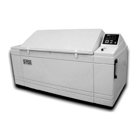
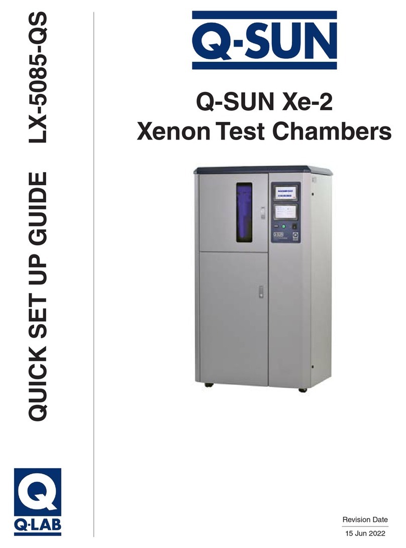
Q-Lab Q-SUN Xe-3 Series User manual

QUICK SET UP GUIDE LX-5080-QS
Q-SUN Xe-3
Xenon Test Chambers
For Models:
X3H X3HDSE
X3HCE X3HBSCE
X3HSE X3HDSCE
X3HSCE X3HDSBSE
X3HBSE X3HDSBSCE
Revision Date
11 Apr 2022
Q-SUN Xe-3
Xenon Test Chambers

2
Table of Contents
Table of Contents
1. Specications, Classications, Symbols (Feb 2015) ............ 3
2. Safety Information ................................................................... 5
2.1 Heat and Electrical Shock Hazards (Dec 2020) ................... 5
2.2 Ultraviolet and Infrared Hazards (Mar 2019) ......................... 7
2.3 Dual Spray System (Oct 2020) ............................................. 8
3. General Description (Oct 2020) .............................................. 9
4. Operating Environment ..........................................................11
4.1 Suitable Environments (May 2020)......................................11
4.2 Unsuitable Environments (May 2020)................................. 12
5. Setup....................................................................................... 14
5.1 Xe-3 Uncrating (Dec 2020) ................................................. 14
5.2 Chiller Uncrating (Apr 2021) ............................................... 19
5.3 Chiller Assembly (Apr 2021) ............................................... 25
5.4 Xe-3 Exhaust Vent Assembly (Dec 2020) ........................... 29
5.5 Back Spray Set Up (Oct 2020)............................................ 32
5.6 Dual Spray Uncrating and Assembly (Dec 2020)................ 33
5.7 Dimensions and Space Requirements (Mar 2020)............. 36
5.8 Electrical (Apr 2022) ........................................................... 38
5.9 Water (Sep 2020)................................................................ 41
5.10 Venting (Dec 2020) ........................................................... 46
6. Start Up................................................................................... 48
6.1 Specimen Mounting (May 2020)......................................... 48
6.2 Q-SUN Xe-3, All “E” Models Control Panel (May 2020) ...... 48
6.3 Q-SUN Xe-3-H Control Panel (May 2020) .......................... 50
6.4 Chiller (May 2020) .............................................................. 51
6.5 Dual Spray (May 2020) ....................................................... 52
7. Warranty (Oct 2020)................................................................ 53
8. Repair and Tester Support (Sep 2020) ................................. 54

Section 1. Specications, Classications, Symbols
3
1. Specications, Classications, Symbols (Feb 2015)
Specications, Classications
●The recommended ambient operating temperature and relative humidity (RH) for the Q-SUN tester is 23 ± 5 °C
and 50 ± 25% RH.
●The maximum ambient operating temperature and humidity is 40 °C and 80% relative humidity.
●Temperatures outside the recommended range may cause chamber temperature and/or humidity faults.
●Transportation and Storage Temperature: -40 °C to 80 °C.
●Installation Category: Category II for transient over-voltages.
●Pollution Control: Pollution Degree 2.
●Sound Pressure Level: Sound Pressure Level does not exceed 75 dBA.
●Altitude: 2000 meters or less.
●Operation: Continuous Rating.
●Supply Connection: Permanently connected or plug/socket connection (industrial type per IEC 6309 or twist lock type
in North America).
●External Disconnect: Required for all connections.
●External Over-Current Protection: Must be rated for not more than 40 A (USA, Canada) or 64 A (Europe).

4
Section 1. Specications, Classications, Symbols
Symbols
Electrical Shock Hazard
Hot Surfaces Hazard
Attention
Finger/Hand Crushing hazard
Local Waste & recycling regulations
per the WEEE Directive 2002/96/EC
on Waste Electrical and Electronic
Equipment

Section 2. Safety Information
5
2. Safety Information
Q-Lab accepts no responsibility for the consequences if the user fails to comply with the instructions in this operating
manual. Q-Lab will accept responsibility for defective parts or components only if the machinery was defective at the time
that the tester was shipped.
●This manual does not claim to address potential safety issues, if any, associated with the use of this product.
●It is the responsibility of the user of this manual to establish appropriate safety and health practices, and to determine
the applicability of regulatory limitations prior to use.
●If the equipment is used in a manner not specied by the manufacturer, the protection provided by the equipment
safety devices may be impaired.
●The Q-SUN meets the European Low Voltage Directive 2014/35/EU and complies with the requirements of
EN 61010-1: 2010 (Third Edition), “Safety of Electrical Equipment for Measurement, Control and Laboratory Use”.
●The Q-SUN meets the European Electromagnetic Directive 2014/30/EC and complies with the requirements of
EN 55011:2007 Radiated and Conducted Emissions – class A.
●Use only parts that have been supplied or recommended by Q-Lab.
2.1 Heat and Electrical Shock Hazards (Dec 2020)
Warning Labels
●Warning: If the equipment is used in a manner not specied by the manufacturer, the protection provided by the
equipment may be impaired.
●Warning labels indicate heat and electric shock hazards inside the Q-SUN tester.
Figure 2.1a: Hot Surface Warning Label Figure 2.1b: Shock Hazard Warning Label
Figure 2.1c: Tester door and access panel locations.
Right Side
Access Panels
Left Side
Access Panels
Lamp Door
Test Chamber
Door
Lower Front
Door

66
Section 2. Safety Information
All Q-SUN models are equipped with an interlock switch (Figure 2.1d) that turns off the xenon lamps when the lamp
access door is opened.
Figure 2.1d: Lamp Door Interlock Switch Location
Figure 2.1e: Humidier Inside Lower Front Door Figure 2.1f: Humidier Hot Surface Label
Humidier
Vapor Hose
CAUTION: The vapor hose and
the humidier are hot.

7
2.2 Ultraviolet and Infrared Hazards (Mar 2019)
The Q-SUN lamps produce UV light that can cause severe sunburn, eye inammation, and damage to your vision. Do not
defeat the switch that turns off lamps when the chamber door is open.
Figure 2.2 below shows the location of the chamber door interlock switch inside the right side top access panel.
NOTE: The right side top access panel is connected to the tester by a ground wire tether. When removing the access
panel it is not necessary to disconnect the wire. The ground wire is long enough to set the access panel on the
ground in front of the tester.
Figure 2.2: Chamber door interlock location (right side top access panel removed).
Section 2. Safety Information

8
Section 2. Safety Information
2.3 Dual Spray System (Oct 2020)
Overview
●Q-SUN Xe-3 models equipped with dual spray (DS) have a separate assembly, which includes the uid reservoir and
an enclosure housing an electrically operated pump system (Figure 2.3).
Electrical Shock Hazards
●Because the Dual Spray system is electrically operated, care should always be exercised when working on or around
the equipment, particularly if the oor is wet.
●The enclosure below the reservoir houses the system pump and other components, and should only be opened by
trained service technicians.
Fluid Hazards
●The uid being introduced into the Q-SUN by the Dual Spray system is determined by the customer’s application and
uid specications are beyond the scope of this manual.
●Fluids that may be corrosive, acidic and/or toxic may be introduced into the Dual Spray system.
●Follow all local, OSHA, EHS, and other applicable material handling safety requirements, recommendations, and
practices when mixing, relling, and disposing of these uids.
●The Dual Spray reservoir and all containers used in conjunction with uid storage should be properly labeled.
●Some uids which may be used in the reservoir of the Dual Spray system can become contaminated with fungus,
bacteria, or other organisms.
●Depending on the uid used, frequent checks and cleaning of Dual Spray components may be required
(see Section 15.5).
●Consideration should be given to mixing small batches of liquid frequently rather than large amounts that could
become contaminated before use.
Figure 2.3: Dual Spray reservoir and pump system enclosure.
Reservoir
Pump
Enclosure

Section 3. General Description
9
Overview
●The LX-5080-QS Q-SUN Xe-3 Quick Setup Guide is not a technical manual.
●This guide provides basic information on uncrating and setting up Q-SUN Xe-3 Xenon Test Chambers.
●A Q-SUN Xe-3 Technical Manual is necessary for a complete understanding of how to operate Q-SUN Xe-3 Xenon
Test Chambers.
o See LX-5080-TM Q-SUN Xe-3 Technical Manual for information on Q-SUN Xe-3 "E" models that feature
enhanced performance, including dual touchscreen control and longer lamp life or higher irradiance capability.
o See LX-5080B-TM Q-SUN Xe-3-H Technical Manual for the basic non-"E" Q-SUN Xe-3-H tester.
Q-SUN Xe-3 Models Covered in This Guide
Model Conguration Control Interface
Xe-3-H H: Controlled Humidity Keypad/LCD
Xe-3-HSE S: Water Spray Dual Touch Screen
Xe-3-HCE C: Chiller Dual Touch Screen
Xe-3-HSCE Chiller + Spray Dual Touch Screen
Xe-3-HBSE BS: Back Spray Dual Touch Screen
Xe-3-HDSE DS: Dual Spray Dual Touch Screen
Xe-3-HBSCE Back Spray + Chiller Dual Touch Screen
Xe-3-HDSCE Dual Spray + Chiller Dual Touch Screen
Xe-3-HDSBSE Dual Spray + Back Spray Dual Touch Screen
Xe-3-HDSBSCE Dual Spray + Back Spray + Chiller Dual Touch Screen
3. General Description (Oct 2020)

10
Section 3. General Description
Partial List of Standard Test Methods Met by Q-SUN Xe-3 Xenon Test Chambers
●Listed below are several widely used standards that can be performed with Q-SUN Xe-3 testers.
●For an extensive list of standards Q-SUN testers can perform see LX-5054 Standards Met by Q-SUN Testers.
ASTM C1442 – Conducting Tests on Sealants Using Articial Weathering Apparatus
ASTM D1248 – Polyethylene Plastic Extrusion Materials for Wire and Cable
ASTM D2565 – Xenon Arc – Plastics for Outdoor Applications
ASTM D3424 – Lightfastness of Printed Material
ASTM D3451 – Testing Coating Powders
ASTM D3794 – Testing Coil Coatings
ASTM D4101 – Polypropylene Plastic Injection and Extrusion Materials
ASTM D4303 – Lightfastness of Artists’ Pigments
ASTM D4459 – Xenon Arc – Plastics for Indoor Applications
ASTM D4798 – Xenon Arc – Bituminous Materials
ASTM D5010 – Testing Printing Inks & Related Materials
ASTM D5071 – Xenon Arc – Exposure of Photodegradable Plastics
ASTM D7869 – Xenon Arc – Transportation Coatings
ASTM G151 – General Guidelines for Exposure of Nonmetallic Materials
ASTM G155 – Xenon Arc – Test Apparatus for Exposure of Nonmetallic Materials
ISO 11341 – Paints – Xenon Arc
ISO 4892-2 – Plastics – Methods of Exposure to Laboratory Light Sources – Part 2: Xenon-Arc Sources
DIN 53 387 – Articial weathering and aging of plastics and elastomers by exposure to ltered xenon arc radiation
(Cycles A & E)

Section 4. Operating Environment
11
4. Operating Environment
The Tester Must Be Located in a Suitable Environment
●All Q-Lab test chambers are sophisticated scientic instruments.
●All tester models must be operated in a suitable controlled environment (Section 4.1).
●Operating the tester in an unsuitable environment (Section 4.2) will void the warranty.
NOTE: Some images in this section show "E" models Xe-3 testers. Except where noted, all
information is exactly the same for non-"E" (Xe-3-H) testers.
4.1 Suitable Environments (May 2020)
Ambient Laboratory Temperature and Humidity
●The recommended ambient operating temperature and relative humidity (RH) for Q-SUN testers is 23 ± 5 °C and
50 ± 25% RH.
●Operating outside the recommended range (or in rare cases, even within it), certain standards or test cycle conditions
may not be achievable.
●Operating outside the recommended range can result in the tester producing chamber temperature and/or humidity
faults.
●Never operate your tester in lab temperatures >40 °C or >80% RH.
●Consult with Q-Lab for more specic information about achievable chamber temperature/humidity values based upon
various ambient lab conditions.
Physical Environment
●A room that is dry, clean, and free of dust, particles, gases, or salt fog.
●A room with an HVAC (heating/ventilation/air-conditioning) system.
●A location away from windows or HVAC vents.
●A location that provides the necessary minimum clearances as specied in Section 5.7.

12
Section 4. Operating Environment
4.2 Unsuitable Environments (May 2020)
Salt Fog or Other Airborne Contamination
●Operating a Q-SUN tester in an unsuitable environment will void the warranty.
●DO NOT install Q-SUN testers in a room with corrosion chambers (Figure 4.2a).
●DO NOT locate a Q-SUN tester in a room with machines or processes that generate dust,
particles, vapors, gases, etc (Figure 4.2b).
Figure 4.2a: Do not install testers in a room
with corrosion chambers.
Figure 4.2b: Do not locate testers in a room
with airborne dust, particles, or gases.
Uncontrolled Temperature and Humidity
●Do not operate the tester in a room with uncontrolled temperature and humidity (Figure 4.2c).
●Do not locate tester near sources of cold or hot air (Figure 4.2d).
Figure 4.2c: Do not locate testers near open windows.
X
X
X

For further detail on laboratory environment requirements, please contact
Q-Lab Repair and Tester Support. See Section 7 for contact information.
13
Section 4. Operating Environment
Figure 4.2d: Keep tester away from
sources of hot or cold air.
Other Unsuitable Environments
●Outdoors: Rain and dust will corrode or short out electrical components.
●Metal Dust / Metal Chips: Do not locate the tester near metal cutting machines or metal grinding machines.
Conductive metal dust or metal chips in the air will damage electronic components.
●Carbon Fibers: Do not operate the tester where carbon bers or carbon reinforced plastic are being cut. The
conductive carbon bers will damage electronic components.
●Conductive Pigments: Do not operate the tester where carbon black or other conductive pigment dust is in the air.
The conductive dust will damage electronic components.
●Other Corrosive Gases: Do not expose the tester to acid fog, SO2gas, or other corrosive gases.
●Excessive Voltage: The electrical supply to the tester must be no more than 10% higher than the voltage listed on the
nameplate.
●Low Voltage: Recurring “brown-outs” or voltages less than 90% of the rated voltage will damage electrical
components.
●Water Leaks from Ceiling: Water leaking onto the tester will damage electrical components.
X
HVAC Vent Directly
Above Tester

14
Section 5. Setup
5. Setup
5.1 Xe-3 Uncrating (Dec 2020)
Carefully read these instructions before uncrating the tester.
Follow all local, OSHA, EHS, and other applicable equipment operation and
material handling safety requirements, recommendations, and practices.
●Q-SUN Xe-3 Testers are shipped in one of two types of crates (Figure 5.1a and Figure 5.1b).
●Labels on the crate indicate the location of the instructions to be opened rst (Figure 5.1c).
●Instructions for uncrating and setting up the tester are located in the envelope shown in Figure 5.1d.
NOTE: Some images in this section show "E" models Xe-3 testers. Except where noted,
all information is exactly the same for non-"E" (Xe-3-H) testers.
Figure 5.1a: This Crate has a Carton Banded to a
Wooden Skid.
Figure 5.1b: This Crate has a Wooden Frame
Surrounding the Carton.
Figure 5.1c: Labels on the crate indicate the envelope to
be opened rst.
Figure 5.1d: Open this envelope for important uncrating
instructions.
Open First Open First

Section 5. Setup
15
Weights
Shipping Weight (Approximate) Main Unit
On Skid With Wooden Crate 363 kg (800 lbs)
On Skid With Carton Only 318 kg (700 lbs)
Tester Weight* 190-233 kg (420-512 lbs)
* Weight varies based on installed options.
Tools Required
Phillips Screwdriver (Wooden Crate Only) Flat Blade Screwdriver Fork Lift*
Pry Bar (Wooden Crate Only) Ratchet and 15 mm (9/16”) Socket Small Ladder or Step Stool
Band Cutter Utility Knife
*A fork lift or other mechanical lifting device is recommended for use in moving the crated tester to the
installation location, and to lift the frame in one piece from the crate with wooden frame.
1. Uncrating instructions are located in this envelope.
Remove and read the instructions.
Go To Step 3.
Crate with
Carton and
Wooden
Frame
Go To Step 7.
Crate with
Carton Only
2. For crate with wooden frame continue with Step 3.
For crate with carton only, go to Step 7.
3. Locate the Phillips screws in the bottom front and
back horizontal boards. 4. Remove all screws.
Screws in
Front
Screws in
Back
Remove
Screws
Remove
Screws

16
5. If a fork lift is available, use it to carefully lift the
wooden frame up and off of the tester.
Use Fork Lift to
Remove Crate
in One Piece
6. If a fork lift is not available, use a pry bar to carefully
remove the horizontal and vertical wooden pieces
off of the tester.
Or Use Pry
Bar to Remove
Crate in Pieces
7. Cut the bands holding the carton to the skid.
Remove the bands.
Cut
8. Carefully lift the carton up and off of the tester.
9. Remove all plastic wrap from around the tester.
Remove
Remove
10. Locate the two (2) exhaust vent stack pieces taped
to the rear corners of the tester marked “Do Not
Throw Away”. These pieces must be saved.
Exhaust
Vent Stack Exhaust
Vent Stack
Save
Save
Section 5. Setup

17
11. Remove the exhaust vent stack pieces (X-6971)
and set aside.
Remove and
Save X2
12. Remove the four (4) corner protectors and all
bubble wrap and tape from around the tester.
Remove Remove
Remove
13. Locate the two (2) latches in the right side lower
access panel.
14. Open the latches and remove the access panel.
Open the lower front door.
15. Locate three (3) bolts in the base of the tester that
secure the tester to the skid. Remove the bolts.
Remove
At least two people are needed to
remove the Q-SUN from the skid.
16. Remove the tester from the skid.
Section 5. Setup
Open
Bolt Cross Section Detail
Skid
Xe-3 Base

18
a. Begin by tilting the Q-SUN and
removing the three foam strips
under the bottom of the unit.
b. “Walk” the Q-SUN off the skid
in the direction parallel to the
boards of the skid.
c. Slide the Q-SUN into place and
adjust the leveling feet so the unit
is level.
d. Remove adhesive tape from
various parts on the inside and
outside of the unit.
1 7. Remove the tester from the skid. 18. Open and remove all parts from separate cartons
shipped with tester.
Section 5. Setup

Section 5. Setup
19
5.2 Chiller Uncrating (Apr 2021)
●For Q-SUN Xe-3 models with chiller (C), follow the instructions in this section to uncrate the chiller unit.
●Carefully read these instructions before uncrating the chiller.
●The tables below list chiller weights and tools needed for uncrating.
●Chillers are shipped in two types of crates (Figure 5.2.a and Figure 5.2.b).
Tools Required
Phillips Screwdriver (Wooden Crate Only) Flat Blade Screwdriver
Pry Bar (Wooden Crate Only) Ratchet and 15 mm (9/16”) Socket
Band Cutter Utility Knife
Fork Lift*
*A fork lift or other mechanical lifting device is recommended for use in moving the
crated chiller to the installation location, and to lift the wooden frame in one piece
from the crate with wooden frame.
Weights
Shipping Weight (Approximate)
On Skid With Wooden Crate 182 kg (400 lbs)
On Skid With Carton Only 136 kg (300 lbs)
Chiller Weight 123 kg (270 lbs)
Figure 5.2.a: This Crate has a Carton Banded to a
Wooden Skid.
Figure 5.2.b: This Crate has a Wooden Frame
Surrounding the Carton.

20
Section 5. Setup
Go To Step 2
Crate with
Carton and
Wooden
Frame
Go To Step 5
Crate with
Carton Only
1. For crate with wooden frame continue with Step 2.
For crate with carton only, go to Step 5.
2. Remove the fasteners in the bottom front and back
horizontal boards.
Fasteners
in Front
Fasteners
in Back
3. If a fork lift is available, use it to carefully lift the
wooden frame up and off the carton in one piece.
Use Fork Lift to
Remove Crate
in One Piece
4. If a fork lift is not available, use a pry bar to carefully
remove the horizontal and vertical wooden pieces
off the carton..
Or Use Pry
Bar to Remove
Crate in Pieces
5. Cut the bands holding the carton to the skid.
Remove the bands.
Cut
6. Carefully lift the carton up and off of the tester.
This manual suits for next models
10
Table of contents
Other Q-Lab Test Equipment manuals
Popular Test Equipment manuals by other brands

M-system
M-system Mini-M M2CDS instruction manual

TMB
TMB ProPlex IQ–4 quick start guide

Fluke Calibration
Fluke Calibration CalPower 6331 user guide

YOKOGAWA
YOKOGAWA DL7440 user manual

Emerson
Emerson Rosemount 5900 Instruction for Installation, Configuration, and Operation

Haug
Haug 12.7229.000 operating instructions