Delta OHM HD2060 User manual

Operating manual
Calibrator for vibration
transducers
HD2060
www.deltaohm.com
English
Keep for future reference.
Companies
/
Brands of
GHM

HD2060 - 2 - V1.0
INDEX
1INTRODUCTION.................................................................................................... 3
2TECHNICAL CHARACTERISTICS ............................................................................ 4
3DESCRIPTION AND MOUNTING OF TRANSDUCER ................................................. 5
4TRANSDUCER CALIBRATION................................................................................. 8
5CALIBRATOR CONFIGURATION........................................................................... 10
6BATTERY............................................................................................................. 12
7STORAGE OF INSTRUMENTS ............................................................................... 13
8SAFETY INSTRUCTIONS...................................................................................... 13
9ORDERING CODES .............................................................................................. 14

HD2060 - 3 - V1.0
1INTRODUCTION
The calibrator HD2060 generates mechanical vibration amplitude controlled with pre-
cision and frequency stabilized by a quartz. Coupling a transducer to the vibrating
base of the calibrator it is possible to check its sensitivity to acceleration, velocity or
displacement. The presence of a rechargeable internal battery, the weight and the
small dimensions as well as the low sensitivity to environmental parameters make it
easy to use the calibrator in the field. The calibrator is equipped with a feedback sys-
tem capable of accurately maintaining the amplitude level set, regardless of the load
associated with the mass of the transducer (within the limits stated in the technical
specifications).
The mechanical vibrations generated by the calibrator are very stable over the time,
with a typical drift of 1% per year. In order to maintain the accuracy, we recommend
the annual calibration at DELTA OHM metrological laboratories. The calibrator notifies
the user about the need to make the periodic check by displaying alternately the signs
"cal" and "exp" on the display.
The backlit display provides a clear indication of acceleration, frequency and the
reaching of the set level. In case of exceeding the maximum permissible load or in
case of low battery, the calibrator alerts the user by displaying an error message and
the operation of the vibrating base is turned off. The automatic stop of the vibration
after the set time and the automatic shutdown function prevent the discharge of the
battery.
The calibrator is equipped with screws and accessories for mounting the transducers,
with external power supply for charging the battery and with calibration report.
Applications:
•In-the-field calibration of acceleration, velocity and displacement transducers.
•Calibration of acceleration sensors used for the measurement of vibrations
transmitted to men in the workplace, according to the standard ISO 8041:2005.
•Calibration of acceleration sensors used to evaluate buildings vibration.
Main specifications:
•Two frequencies of emission: 15.915 Hz at 1 m/s2and 0,1 g
159.155 Hz at 10 m/s2and 1 g
•Low distortion accelerations, independent from the mass of the transducer
•Absence of dispersed magnetic field.
•Backlit display with the indication of the acceleration level stabilization.
•Internal rechargeable battery which allows 2 hours of continuous operation at
15.915 Hz and 7 hours of continuous operation at 159.155 Hz.

HD2060 - 4 - V1.0
2TECHNICAL CHARACTERISTICS
Maximum load of the
vibrating base
Traction force: 10 N
Pressure: 30 N
Transverse: 2 N
Mass of the transducer Maximum 150 g at 15.915 Hz
Maximum 30 g at 159.155 Hz
Emission frequency
tolerance
± 0.1%
Emission amplitude
tolerance
± 3%
Distortion Less than 3% at 15.915 Hz
Less than 0.5% at 159.155 Hz
Duration of individual
emission
Settable from 120 seconds to 10 minutes. Automatic turn OFF
Transverse acceleration Less than 10% at 15.915 Hz
Less than 20% at 159.155 Hz
Mounting of the
transducer
Threaded hole UNF 10-32 at 90° ±1°
Working temperature/RH 0…+40 °C / 0…85 %RH not condensing
Stabilization time Less than 30 s
Display Backlit with indication of:
Frequency generated
Acceleration generated
Stabilization of the vibration
Remaining battery charge
Calibration deadline
Power supply Rechargeable NiMH battery pack 1.2V x 4, capacity 1600
mA/h (BAT-40)
100-240 Vac / 12 Vdc 1 A stabilized power supply (SWD10)
Authonomy with full
charged battery
2 hours of continuous use at 15.915 Hz
7 hours of continuous use at 159.155 Hz
Battery charging time 4 hours at 12 Vdc 1A
Auto power off After an inactive period of time equal to 3 times the time of
solicitation set
Dimensions 115 x 93 x 63 mm
Weight 930 g including battery
The exceeding of the limits ma
y
permanently damage the vibrating base
HD2060 - 5 - V1.0
3DESCRIPTION AND MOUNTING OF TRANSDUCER
H D 2 0 6 0
START
STOP
VIBRATION FIELD CALIBRATOR
ISO 8041:2005 - Annex A
Freq.: 15.915 Hz / 159.155 Hz
Acc.: 1m/s (0.1g) / 10m/s (1g)
22
Acc.: 1m/s (0.1g) / 10m/s (1g)
22
CHARGE
SETUP
** DELTA OHM **
** HD2060 **
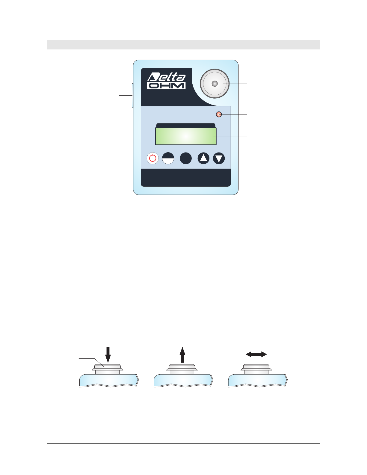
Fig. 3.1: Description
TRANSDUCER MOUNTING
The calibrator HD2060 presents a flat circular steel fixing base (see Figure 3.1), resis-
tant to abrasions, with a UNF 10-32 threaded hole in the center for the mounting of
the transducers.
The fixing base can freely rotate on its housing so as to avoid damage to the calibra-
tor when mounting the sensors and applying the tightening. To fix the accelerometer
using a screw it’s sufficient a 1-2 Nm tightening force, compatible with a manual op-
eration. For maximum measurements repeatability, the use of a torque wrench is rec-
ommended.
Maximum applicable forces to the fixing base are: 30 N pressure force, 10 N traction
force and 2 N transverse force (see picture 3.2). Applying a load which exceeds
specified limits can permanently damage the HD2060 calibrator.
M 30 NAX M 10 NAX M2NAX
Fig. 3.2: Maximum load limits for vibrating base
As an alternative to screw mounting, it’s possible to fix the sensor onto vibrating base
using double-sided tape, wax or quick glue; for this can be used the supplied adapter
HD6245.1 (see picture 3.3) to be mounted between vibrating base and transducer. To
Vibratin
g
base
LCD
Keyboard
Batter
y
char
g
e
LED
Power su
pp
l
y
connector
Vibratin
g
Base

HD2060 - 6 - V1.0
avoid an excessive pressure on the vibrating base, we recommend to glue the trans-
ducer on the HD6245.1 adapter before screwing it to the vibrating base.
Fig. 3.3: Adhesive Mounting
To calibrate axes orthogonal to the mounting axis on triaxial accelerometers, it is sup-
plied the adapter HD2060.20, complete with UNF 10-32 dual threading screw to fix
the adapter to the mounting base and screw with UNF 10-32 threading to fix the sen-
sor to the adapter (see picture 3.4).
Fig. 3.4: Use of adapter HD2060.20
If you use the HD2060.20 adapter to calibrate at 16 Hz perpendicular axis of a triaxial
accelerometer having a mass greater than 30 g, it is necessary to balance the load
using a counterweight equal to that of the transducer to be mounted, as shown in fig-
ure 3.5.
Fig. 3.5: Use of counterweights
Calibrator must be placed on a flat horizontal surface, possibly free from external vi-
brations. In order to check that transmitted vibration level from supporting surface is
HD2060.20
Vibrating Base
Transduce
r
Counterweigh
t
Vibrating Base
Transduce
r
HD6245.1
Vibrating bas
e
Triaxial transduce
r
Transducer’s mounting
screw
HD2060.20
Double threading screw for mounting
of HD2060.20 on Vibrating base

HD2060 - 7 - V1.0
negligible it is sufficient, after transducer has been fixed to the mounting base, to ve-
rify that acceleration on the measurement chain with calibrator turned OFF is below
1/5 of calibration level. For example, if a calibration has to be made at 15.915 Hz with
1 m/s2amplitude level, acceleration on the measurement chain when calibrator is OFF
should be less than 0.2 m/s2.
During calibration solicitation it’s necessary to avoid unbalances on the base, taking
care of transducer’s connection cable positioning, in order to minimize the transverse
load. Transducer should be mounted so that the load is centered on the base.
HD2060 - 8 - V1.0
4TRANSDUCER CALIBRATION
HD2060 can calibrate acceleration, velocity and displacement sensors. Emission fre-
quencies are chosen to allow an easy conversion among the three measurement units
as shown in the table below.
Frequency [Hz] Acceleration
[m/s2] Velocity [mm/s] Displacement [µm]
15.915 1 10 100
0.98 9.81 98.1
159.155 10 10 10
9.81 9.81 9.81
Selection of the right frequency depends on the type of transducer and measurement
application. For example, according to ISO 8041:2005 requirements, vibration trans-
ducers used in the workplace to evaluate vibration transmitted to hand –arm system ,
must be checked at 159.155 Hz, while those used for vibrations transmitted to the
whole body must be checked at 15.915 Hz.
Some transducers are designed for measurement at very low frequencies, and cannot
be calibrated at 160 Hz. If the application or the type of transducer don’t put con-
straints to the choice, 159.155 Hz frequency is preferable because, in addition to
higher acceleration level, provides a lower distortion and lower sensitivity to vibrations
induced from the support surface.
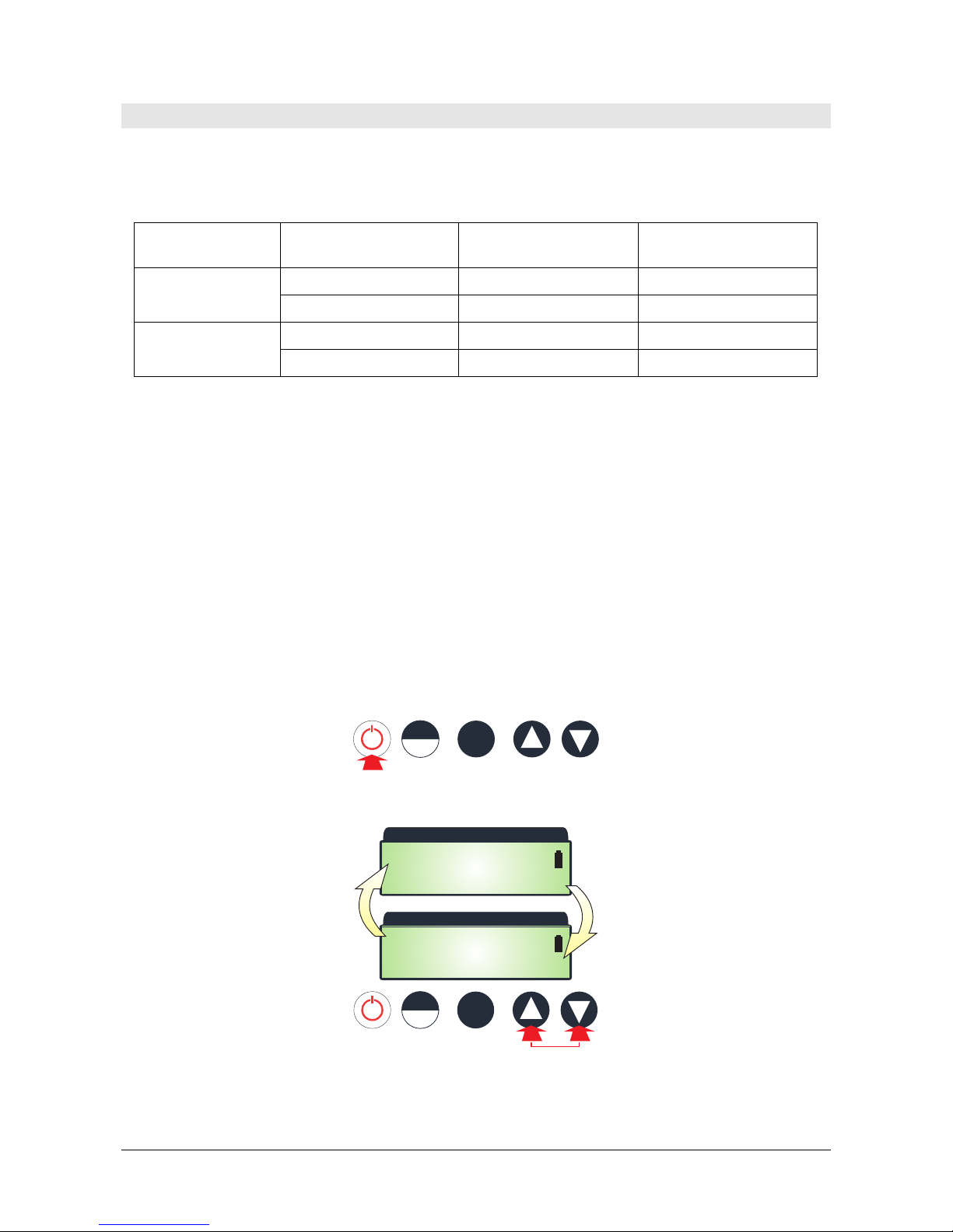
Procedure:
1. After the transducer has been correctly mounted on the vibrating base, power ON
the calibrator by pressing the ON/OFF key.
START
STOP SETUP
2. Use the arrow keys to select the emission frequency.
HD2060H D 2 0 6 0
F= 16Hz |OUT|
A=0.1g |OFF |
HD2060H D 2 0 6 0
F=160Hz |OUT|
A= 1g |OFF |
START
STOP SETUP
Note: as concerns modification of acceleration amplitude and emission duration
please see configuration paragraph.
HD2060 - 9 - V1.0
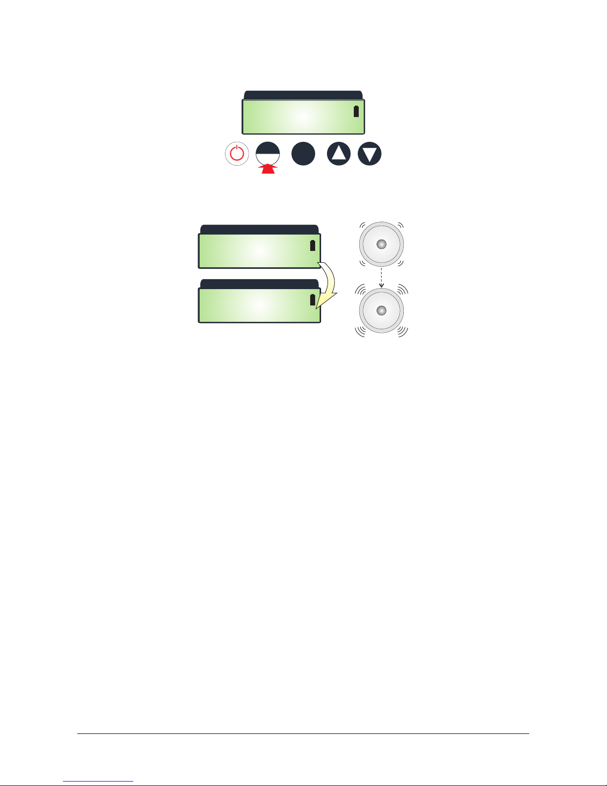
3. In order to start emission, press START/STOP key.
START
STOP SETUP
HD2060H D 2 0 6 0
F=160Hz |OUT|
A= 1g |OFF |
4. On the display is shown the indication WT ("Wait") until vibration emission is suffi-
ciently steady. When emission is stable, it appears the indication ON.
HD2060H D 2 0 6 0
F=160Hz |OUT|
A= 1g |WT |
HD2060H D 2 0 6 0
F=160Hz |OUT|
A= 1g |ON |
5. Emission stops automatically after the time period set on the calibrator is elapsed.
In order to manually stop emission, press the START/STOP key.
HD2060 - 10 - V1.0
5CALIBRATOR CONFIGURATION
By sequentially pressing the SETUP key, the following information are displayed:
•Generated Acceleration (AMPL. SETUP)
•Emission Duration (VIBR. TIME)
•Date and time (DATE TIME)
•Calibrator serial number (SERIAL NUM.)
•Calibration Date (CALIB. DATE)
•Firmware Version (FIRM. VER.)
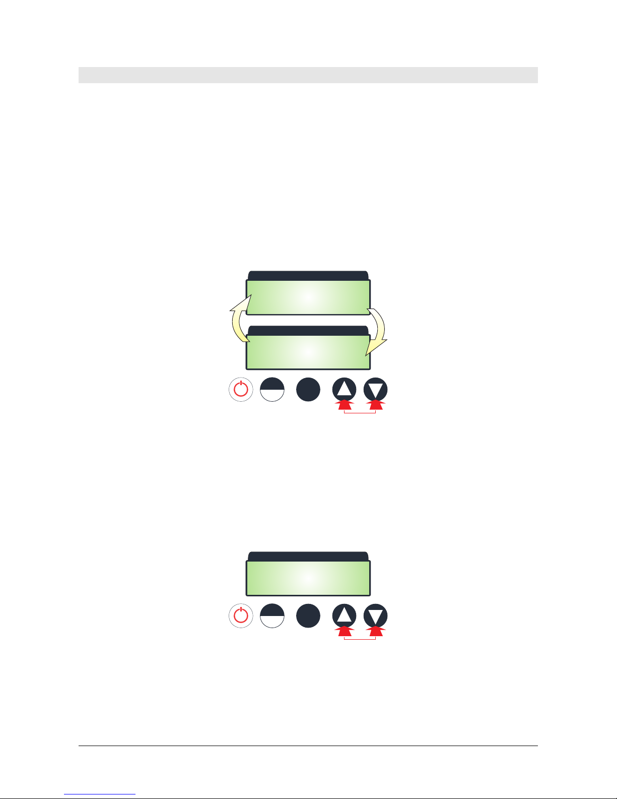
Setting Acceleration Amplitude:
Press SETUP key until the AMPL. SETUP screen is shown, then select required accele-
ration value using the arrow keys.
HD2060H D 2 0 6 0
--AMPL. SETUP--
AMPL= 10m/s
2
HD2060H D 2 0 6 0
--AMPL. SETUP--
AMPL= 1g
START
STOP SETUP
Acceleration values that can be set, depend on the emission frequency selected. For
emission frequency of 15.915 Hz can be set acceleration amplitudes of 1 m/s2and
0.1g (0.98 m/s2). For emission frequency of 159.155 Hz can be set acceleration am-
plitudes of 10 m/s2and 1g (9.81 m/s2).
Setting Emission Duration:
Press the SETUP key until the VIBR. TIME screen appears, then select required emis-
sion duration using the arrow keys.
HD2060H D 2 0 6 0
-- VIBR. TIME --
240 sec
START
STOP SETUP
Duration can be set from 120 seconds up to 10 minutes in steps of 10 seconds.
Setting date and time:
Press SETUP key until the DATE TIME screen appears, then modify the year field using
the arrow keys.

HD2060 - 11 - V1.0
HD2060H D 2 0 6 0
-- DATE TIME --
2012/07/04 09:45
START
STOP SETUP
In order to set the next fields (month, day, hour, minute), just press SETUP key until
the desired field starts blinking, then modify it using the arrow keys.
Exit from configuration mode:
In order to exit from the configuration mode, hold down the SETUP key for at least 2
seconds.
Settings are stored in the calibrator’s internal memory and remain stored even if the
device is turned OFF. When the calibrator is powered ON, it always starts with the lat-
est configuration set.

HD2060 - 12 - V1.0
6BATTERY
The battery symbol on the display continuously provides the charge battery status. As
the battery discharges, the symbol "empties". When the charge is insufficient for cor-
rect device operation, the symbol starts blinking and it will be not possible to activate
the emission of the vibrating base.
In order to charge the batteries, connect the SWD10 power supply to the input plug
positioned on the calibrator’s side. During battery charge, the “CHARGE” red LED is
ON. The LED will turn OFF when the charge is completed. The time necessary for a full
charge is about 4 hours.
Power supply has a dual function: supplies the device and charges the NiMH battery.
When power supply is plugged in, the battery symbol on the display, is substituted by
the symbol of a plug.
In order to preserve over time the battery capacity, it is recommended to
make a complete charge cycle at least one time every six months.
The battery can be charged and discharged hundreds times, but it loses its capacity
with the use during time. If, when the battery is fully charged, the operation autono-
my is not sufficient, it’s necessary to replace the battery pack.
As spare part use only original Delta OHM battery pack BAT-40 and proceed as fol-
lows:
•If plugged in, disconnect external power supply.
•Loosen the two screws to remove the cover of battery housing placed on the
bottom of calibrator.
•Disconnect the battery taking care not to tear the wires.
•Connect the new battery: the connector has a reference that avoids uncorrect
operation.
•Place the new battery in the housing.
•Close the battery housing tightening the two screws.
Note: dispose used batteries according to safety normatives. Don’t throw used batte-
ries in the municipal waste; do not put the batteries into contact with flames or high
temperature surfaces.

HD2060 - 13 - V1.0
7STORAGE OF INSTRUMENTS
Storage conditions of the instrument:
•Temperature: 0...+40 °C.
•Humidity: less than 90 %RH no condensation.
•For storage, avoid places where:
•There is a high level of humidity;
•Instruments are exposed to direct sun radiation;
•Instruments are exposed to a high temperature source;
•There are strong vibrations;
•There is vapor, salt and/or corrosive gases.
8SAFETY INSTRUCTIONS
General instructions for safety
The instrument has been manufactured and tested in compliance with the safety stan-
dard EN61010-1:2010 “Safety requirements for electrical equipment for measurement,
control and laboratory use” and left the factory in a safe and secure technical condition.
The regular functioning and operational safety of the instrument can be ensured only
if all normal safety measures, as well as the specific measures described in this ma-
nual, are followed.
The regular functioning and operational safety of the instrument can only be guaran-
teed under the climatic conditions specified in the manual.
Do not use the instruments in places where there are:
•Rapid ambient temperature variations that may cause condensation.
•Corrosive or flammable gases.
•Direct vibrations or bumps to the instrument.
•High-intensity electromagnetic fields, static electricity.
If the instrument is transported from a cold environment to a warm one, or vice ver-
sa, the formation of condensation may cause disturbances to its functioning. In this
case, wait until the temperature of the instrument reaches room temperature before
putting into operation.
Obligations of the User
The user of the instrument must ensure compliance with the following standards and
guidelines for the treatment of hazardous materials:
EEC directives on workplace safety
National low regulations on workplace safety
Accident prevention regulations

HD2060 - 14 - V1.0
9ORDERING CODES
HD2060 Portable calibrator for acceleration, velocity and displacement trans-
ducers. Double emission frequency (15.915 Hz and 159.155 Hz).
Backlit LCD display. Power supply with internal rechargeable battery
or external 12Vdc power supply. Includes: support (HD2060.20)
with UNF 10-32 screw for triaxial accelerometers mounting, insulated
base (HD6245.1) with integrated UNF 10-32 screw for accelerome-
ters adhesive mounting, rechargeable internal battery (BAT-40),
mains power supply (SWD10), carrying case and calibration report.
Accessories
SWD10 100-240 Vac / 12 Vdc 1 A stabilized power supply.
BAT-40 Rechargeable NiMH battery pack 1.2 V x 4.
HD6245.1 Insulated base with integrated UNF 10-32 screw for accelerometers
adhesive mounting
HD2060.20 Support for the lateral mounting of tri-axial accelerometers with 10-
32 UNF mounting screw
Delta OHM LAT N° 124 metrology laboratories are ISO/IEC 17025 accredited by AC-
CREDIA in Temperature, Humidity, Pressure, Photometry/Radiometry, Acoustics and
Air Speed. They can provide certificates for the accredited quantities.

GUARANTEE
TERMS OF GUARANTEE
All DELTA OHM instruments are subject to accurate testing, and are guaranteed for 24 months from the
date of purchase. DELTA OHM will repair or replace free of charge the parts that, within the warranty
period, shall be deemed non efficient according to its own judgement. Complete replacement is excluded
and no damage claims are accepted. The DELTA OHM guarantee only covers instrument repair. The
guarantee is void in case of incidental breakage during transport, negligence, misuse, connection to a
different voltage than that required for the appliance by the operator. Finally, a product repaired or
tampered by unauthorized third parties is excluded from the guarantee. The instrument shall be returned
FREE OF SHIPMENT CHARGES to your dealer. The jurisdiction of Padua applies in any dispute.
The electrical and electronic equipment marked with this symbol cannot be disposed of in public
landfills. According to the Directive 2011/65/EU, the european users of electrical and electronic
equipment can return it to the dealer or manufacturer upon purchase of a new one. The illegal
disposal of electrical and electronic equipment is punished with an administrative fine.
This guarantee must be sent together with the instrument to our service centre.
IMPORTANT: Guarantee is valid only if coupon has been correctly filled in all details.
Instrument Code: HD2060
Serial Number
RENEWALS
Date Date
Inspector Inspector
Date Date
Inspector Inspector
Date Date
Inspector Inspector

GHM GROUP – Delta OHM | Delta Ohm S.r.l. a socio unico
Via Marconi 5 | 35030 Caselle di Selvazzano | Padova | ITALY
Phone +39 049 8977150 | Fax +39 049 635596
www.deltaohm.com | info@deltaohm.com
The quality level of our instruments is the result of the constant development of the product. This may
produce some differences between the information written in this manual and the instrument you have
purchased. We cannot completely exclude the possibility of errors in the manual, for which we apologize.
The data, images and descriptions included in this manual cannot be legally asserted. We reserve the
right to make changes and corrections with no prior notice.

GHM GROUP – Delta OHM | Delta Ohm S.r.l. a socio unico
Via Marconi 5 | 35030 Caselle di Selvazzano | Padova | ITALY
Phone +39 049 8977150 | Fax +39 049 635596
www.deltaohm.com | info@deltaohm.com
V1.0
02/03/2018
Other manuals for HD2060
1
Table of contents
Other Delta OHM Test Equipment manuals


